


-
Type
- Dante
- Networking
- Control
-
System Management
- Composer Management Software
- SymVue Screen Authoring
- AV-Ops Center Remote Monitoring
- ARC-WEB Control Interface Signal Processing
- D100 AVoIP DSP Server
- Radius NX AVoIP DSP
- Prism AVoIP DSP
- Edge AVoIP DSP
- DSP I/O Expansion Cards
- Jupiter DSP
- Zone Mix 761 DSP I/O Connectivity
- xIO Bluetooth Endpoints
- xIO XLR Endpoints
- xIO AVoIP DSP Audio Expanders Control Systems
- T-Series Touchscreen Controllers
- W-Series Controllers
- Control Server for Personal Devices
- xControl GPIO Expander
- ARC-Series Controllers
Combined Analog and Remote Mic Switch Super-Module in Composer
Product:Composer Management Software
Type: Control
Overview
This Tech Tip provides information and instructions pertaining to the combined Analog and Remote Mic Switch Super-Module that can be located in the Tools folder of the Super-Module Library within Symetrix Composer software. Composer is an award winning CAD program used to create site file designs perfectly suited to each and every application.
This Super-Module can be used to combine the mic switch operation from an analog input and remote control device (ie, ARC remote, ARC-WEB, or third-Party control). Normally when using the external analog control inputs, the analog control values will supersede and override software control.
com 1
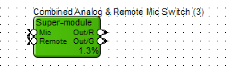
This Super-Module will allow a single mic switch to be controlled from the analog input and software. The Super-Module also will allow for the switch or mute state to be viewed by the remote control device and drive an external control output (ie, LED).
Implementing this Super-Module
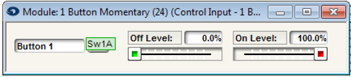
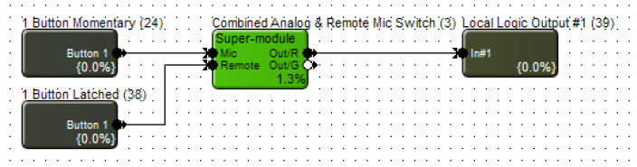
1. Wire a 1 Button Momentary module to the Mic input of the Super-module.

2. Assign the “On” button of the momentary button module to the analog mic switch.
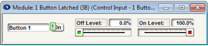
3. Wire a 1 Button Latched module to the Remote input of the Super-module.
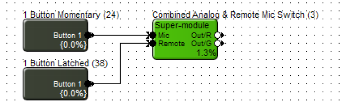
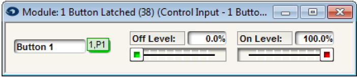
4. Assign control number to the “On” button of the 1 Button Latched module. This control assignment will be used for the remote control assignment of the remote controller (ie, ARC remote, ARC-WEB, or third-party control).
5. Click the “On” button of the 1 Button Latched module so the button is on and save the on state to a preset. Label this preset as Mute. This example used preset #1.
6. Click the “On” button of the 1 Button Latched module again so the button is off and save the off state to a preset. Label this preset as Unmute. This example used preset #2.
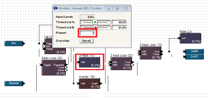
7. Open the Super-module design and make sure the Mute preset trigger matches the preset that was assigned to the 1 Button Latched module. This example uses Preset #1 for Mute.
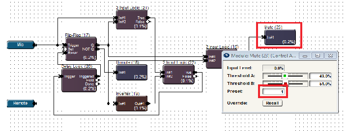
8. Make sure the Unmute preset trigger matches the preset that was assigned to the 1 Button Latched module. This example uses Preset #2 for Unmute.
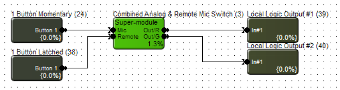
9. Wire a Logic Output module to the Out/R of Super-module. The Logic Output could be a Local Logic Output or Remote Logic Output. This output will be used to drive the red LED of the analog mic switch. This example uses Local Logic Output #1 for the red LED.
10. Wire a Logic Output module to the Out/G of Super-module. The Logic Output could be a Local Logic Output or Remote Logic Output. This output will be used to drive the green LED of the analog mic switch. This example uses Local Logic Output #2 for the green LED.
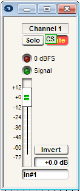
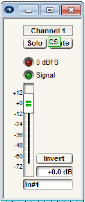
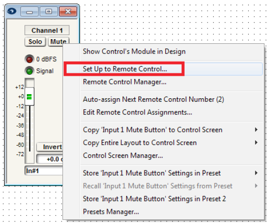
11. Open either a Gain Module or Automixer used in the signal processing and routing of the microphones.
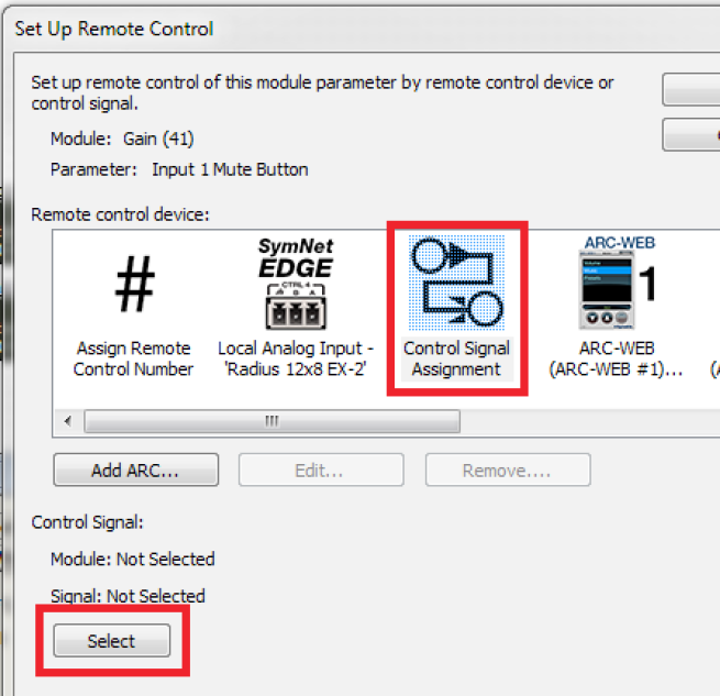
12. Right-click on the channel Mute button.
13. Select “Set Up Remote Control.”
14. Select “Control Signal Assignment” for the Remote Control Device. Then click “Select.”
15. Expand Combined Analog & Remote Mic Switch.
16. Select Out/R and click OK.
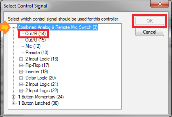
17. The mute button of the Gain or Automixer will now be controlled by the state of the red LED of the Super-Module. When the red LED is active, that channel will be muted. When the red LED is inactive, the channel will be unmuted.
Mute