


-
Type
- Dante
- Networking
- Control
-
System Management
- Composer Management Software
- SymVue Screen Authoring
- AV-Ops Center Remote Monitoring
- ARC-WEB Control Interface Signal Processing
- D100 AVoIP DSP Server
- Radius NX AVoIP DSP
- Prism AVoIP DSP
- Edge AVoIP DSP
- DSP I/O Expansion Cards
- Jupiter DSP
- Zone Mix 761 DSP I/O Connectivity
- xIO Bluetooth Endpoints
- xIO XLR Endpoints
- xIO AVoIP DSP Audio Expanders Control Systems
- T-Series Touchscreen Controllers
- W-Series Controllers
- Control Server
- xControl GPIO Expander
- ARC-Series Controllers
-
Type
- Dante
- Networking
- Control
-
System Management
- Composer Management Software
- SymVue Screen Authoring
- AV-Ops Center Remote Monitoring
- ARC-WEB Control Interface Signal Processing
- D100 AVoIP DSP Server
- Radius NX AVoIP DSP
- Prism AVoIP DSP
- Edge AVoIP DSP
- DSP I/O Expansion Cards
- Jupiter DSP
- Zone Mix 761 DSP I/O Connectivity
- xIO Bluetooth Endpoints
- xIO XLR Endpoints
- xIO AVoIP DSP Audio Expanders Control Systems
- T-Series Touchscreen Controllers
- W-Series Controllers
- Control Server
- xControl GPIO Expander
- ARC-Series Controllers
Managing digital audio on a network may seem like a daunting task, particularly when the network is not a dedicated network switch, or series of switches used only for audio, but instead is shared amongst a variety of network devices, such as printers, PCs, control equipment, and servers, all sharing network bandwidth with the networked digital audio.
Understanding how to manage networked audio becomes extremely important when commissioning a system in which an existing corporate network is intended to provide the network infrastructure between two or more Dante capable; devices, third party consoles, or I/O end points. In such a scenario, managing the Dante audio becomes a necessary consideration; however, Dante has made the job of managing the unicast and multicast audio simple and straight forward.
First, it is best to understand the basics of unicast and multicast network traffic and how it relates to Dante networked audio, then cover the method for managing these two protocols.
Within Composer there are two types of Dante flows that can be defined; unicast and multicast.
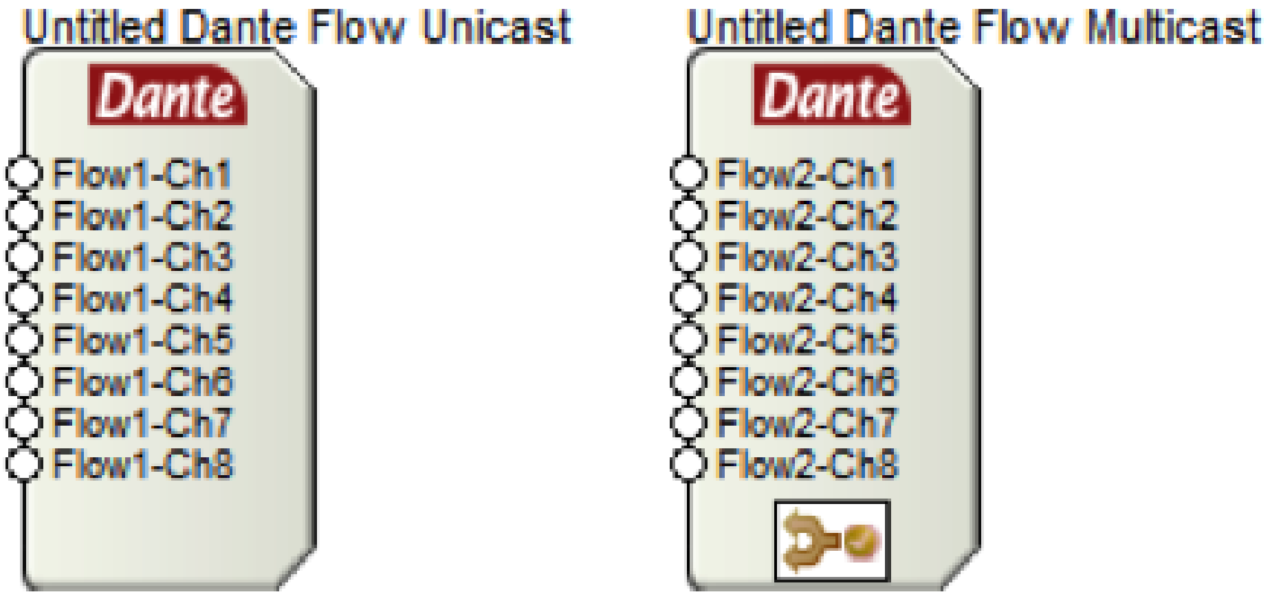
Unicast: A unicast flow is transmitted from one Dante device and is routed to exactly one other receiving Dante device. A unicast flow is routed across the network via a destination IP address embedded within the header of the Dante network packet.
Multicast: A multicast flow is transmitted from one Dante device and is typically routed to multiple receiving Dante devices. A multicast flow, when not managed, will be transmitted to every device connected to the network.
It is recommended to use unicast Dante flows whenever possible, especially when Dante is on a shared data network. This eliminates unnecessary network traffic by ensuring the Dante audio travels directly from one IP address to another, rather than proliferating across the entire network. That being said, when a Dante channel is routed to three or more devices, it is a more efficient use of the network bandwidth to use multicast flows.
The fact that multicast Dante, when not managed, will be transmitted to every device connected to the network means that each network device must analyze the multicast packet of data, determine if the packet must be received, and then either receive the packet or disregard it and continue operation. For devices without Dante capabilities, receiving large amounts of multicast data can lead to slower processing speeds, sluggish network response, and other performance related issues. In fact, a type of denial-of-service-attack utilizes this exact method for sabotaging network service.
The question then becomes, is it possible to manage multicast Dante flows on the network such that these multicast flows are only routed to the LAN ports of the Dante receiving devices? The answer is “yes”, and in fact, this management is very easy to implement. This management process is called “IGMP snooping”.
IGMP snooping is a feature of a managed network switch that allows it to listen in on conversations between the multicast source, receivers, hosts, and routers. By listening in to these conversations, the switch builds and maintains a map of which links need which IP multicast streams, such that multicast streams may be filtered from the links which do not need them, and thus ports receive only specific multicast traffic they have subscribed to.
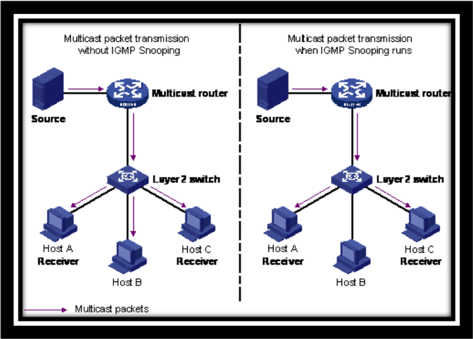
From the diagram above, it should be clear that as a standard practice IGMP Snooping should be enabled on all shared networks with multicast Dante flows.
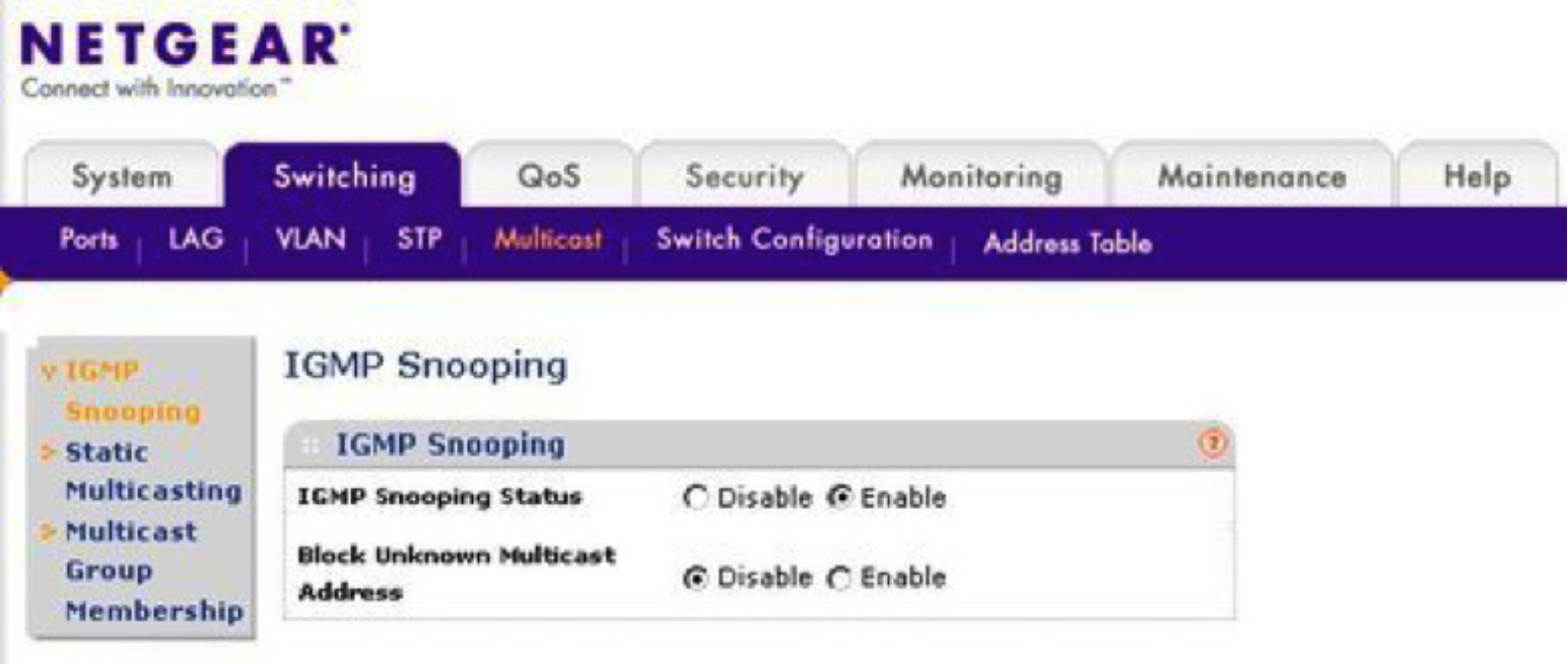
Simply enabling the IGMP Snooping feature is all that is required, and from that point on, Dante multicast traffic will be filtered, kept from broadcasting to all devices on the network, and routed only to links containing Dante devices subscribed to the multicast flow.
Composer hardware utilizes Dante as the digital audio bus for routing audio between hardware and 3rd party Dante enabled hardware. Setting up a Dante network is made simple, quick, and easy with Dante’s ability to receive an IP address using DHCP and then auto-resolve connections between units. That being said, there are times when it will be specified or ideal for the Dante ports to have specific and unique, static IP addresses. Composer hardware allows for assigning static IP addresses to the Dante ports using Dante Controller.
Follow these easy steps to assign a static IP address to a Dante port on a device:
Step 1: Download Dante Controller from the Audinate website:
http://www.audinate.com/index.php?option=com_content&view=article&id=305
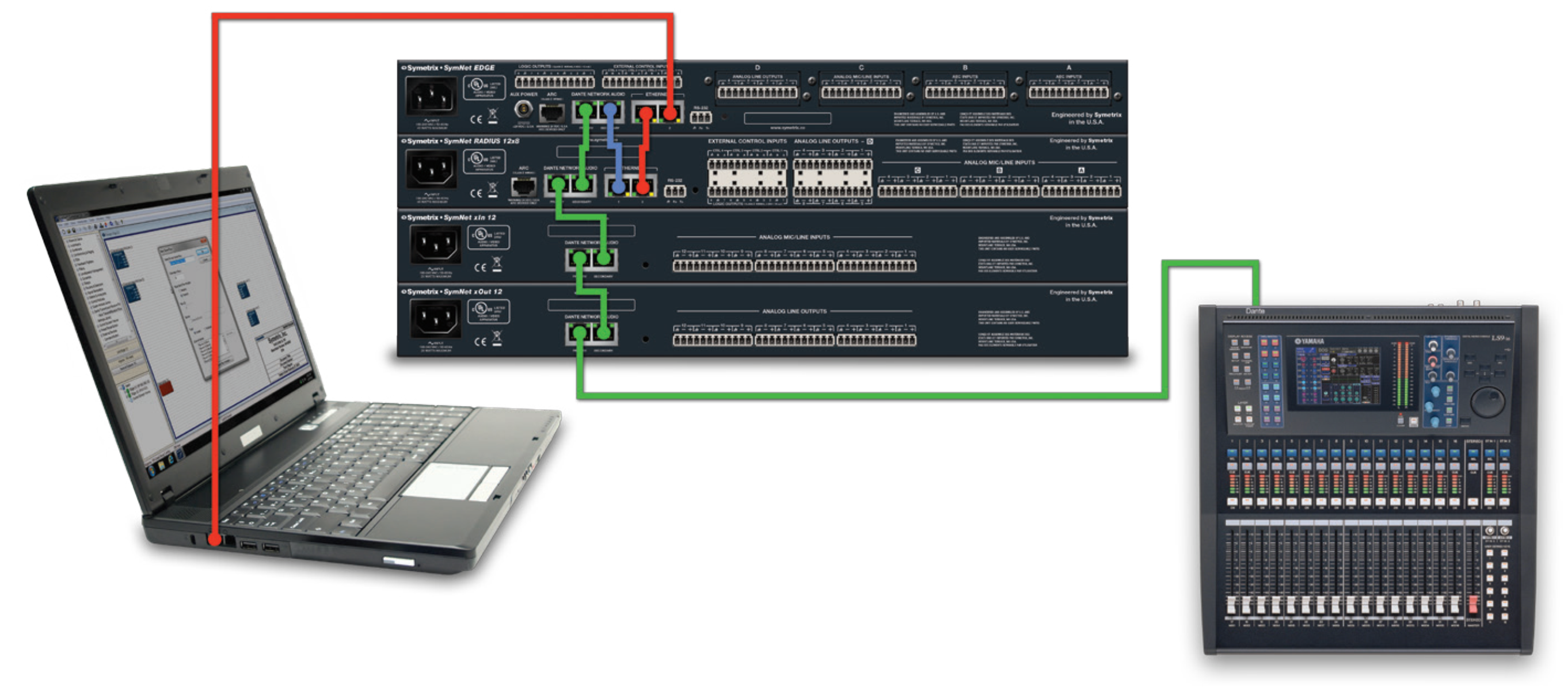
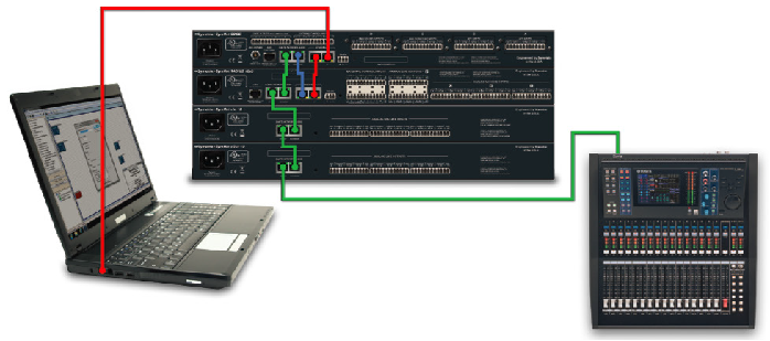
Step 2: Plug the PC’s LAN port into the Dante network.
Note: If it is desired to stay online with the system using Composer while simultaneously monitoring or assigning static IP addresses to the Dante network, use a CAT5 or CAT6 jumper cable to merge the control port with the Dante network.
See the blue wire below:
Step 3: Launch Dante Controller and verify that it locates the Dante devices on the Device Status Tab.
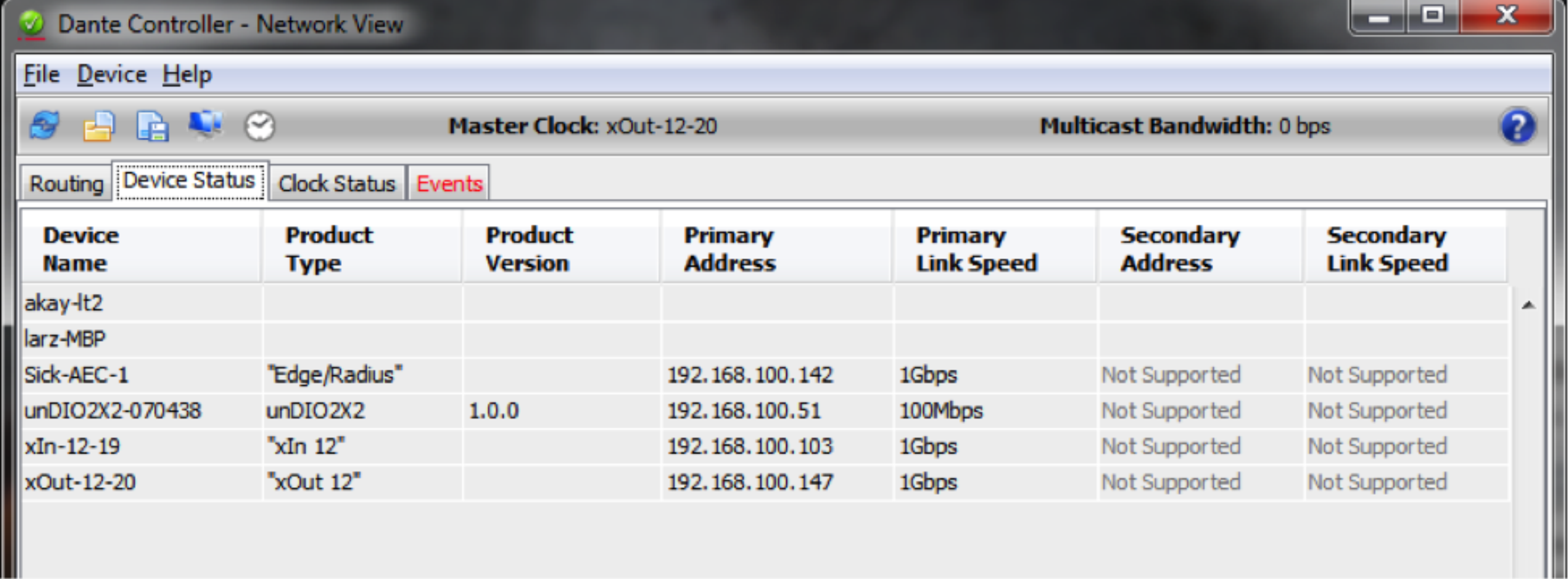
Step 4: Double Click on the “Device Name” of the Composer unit to open the “Device View”.
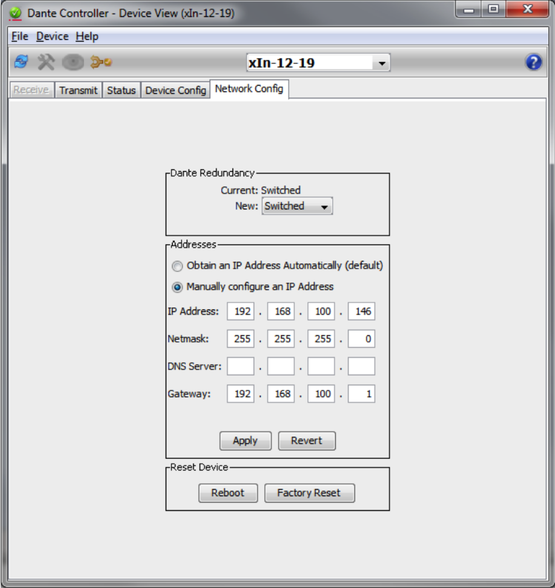
Step 5: Go to the Network Config tab and select “Manually configure an IP Address”.
Step 6: Enter the static IP Address, Netmask, and Gateway.
Note: Be sure to use unique IP settings.
Step 7: Hit “Apply” to write the new static IP information to the Dante port of the Composer hardware.
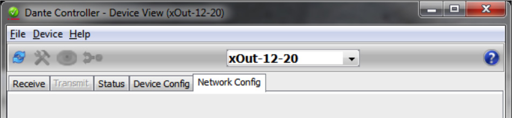
Step 8: Use the drop down at the top of the Device View page to select the next Composer unit and repeat Steps 5, 6 and 7.
Composer is intuitive, open architecture, drag-n-drop DSP software for any and all commercial or live sound applications using Symetrix Dante enabled DSP hardware. Additionally, Audinate’s Dante has arrived in full force and is quickly becoming the industry standard, cross platform, network audio buss of choice in the commercial A/V and live sound market.
This tech tip provides a clear and concise set of instructions for both initial setup of Composer to Dante enabled hardware and/or troubleshooting a Dante network in roughly 5 minutes. Simply put, when setting up or troubleshooting any complex system “Less is more”. It is easier to get to the root of any problem when all moving parts have been minimized. Start small and build up to something bigger, that way any issue becomes apparent immediately rather than being buried in a slew of variables, making it much harder to identify.
When setting up a Dante network with Composer hardware the different units may be specified to be installed in different locations across a 3rd party network. Furthermore, Dante may be specified to be in “redundant” mode. However, for initial setup and troubleshooting of a Composer / Dante network of 10 Dante enabled devices or less, it is advised to first daisy chain the units together with Dante in “switched” mode, which is the factory default.
Once audio is successfully passing between the daisy chained units, proving that all Dante devices are communicating normally and that there are no hardware failures, then and only then (if specified) configure the Dante ports to redundant mode and move the hardware to their respective locations across the 3rd party network.
Steps for initial setup of Dante enabled devices (10 or fewer Composer devices):
1) Direct connect all Composer / Dante enabled units together by daisy chaining them:
• Start by connecting the primary Dante port of the first unit to the secondary Dante port of the second unit and continue until all units are daisy chained together.
2) Connect the PC to the DSP’s Ethernet port:
• The PC which has Composer and Dante Controller installed should connect to the right Ethernet port on the first DSP in the daisy chain, such as an Edge or Radius, which has dual Ethernet ports.
3) Link the Ethernet control network and the Dante network together temporarily for setup:
• On the top unit in Step 2, connect the left Ethernet port to the secondary Dante port.
4) Connect any 3rd party Dante device to the primary Dante port on the bottom unit in the daisy chain:
• If there is more than one 3rd party Dante enabled device, connect them to a common switch, and plug the primary Dante port of the bottom unit in the daisy chain into the same switch.
5) Open up Composer and connect to all units:
• The steps for connecting DSPs in Composer software to their respective hardware units is outlined in depth in the Composer certification online training.
• It is advised to leave all units and the PC in DHCP for initial setup
6) Push a site file into the system and check to confirm Dante passes between all units:
• If Dante passes between all units as it should, you can now:
o Switch to Redundant mode if necessary.
o Move the units to their respective distributed locations.
o Disconnect the Ethernet and Dante networks.
o Assign static IP addresses to hardware if needed.
• If Dante does not pass between all units, proceed to Step 7:
7) If Dante is not passing audio or a unit is not seen by Composer, open Dante Controller.
• Since the Ethernet port and Dante secondary port are connected together in Step 3, the PC can run Composer and Dante Controller simultaneously.
• Check Dante Controller to see if all of the Dante enabled units are recognized.
8) If Dante Controller cannot recognize a particular unit:
• Check CAT-5 cable connections
• Hard reset units with the hard reset button next to the Ethernet port, and then upgrade firmware being careful not to interrupt the upgrade process.
• Reconnect the units in Composer software and check Dante Controller to see if all units are present and accounted for.
9) If you’re still having issues, contact Symetrix support at support@symetrix.co
• Also check these additional Symetrix Dante resources:
o Know-it-Use-It-Troubleshoot-it-Dante.pdf
o Record-Audio-Dante.pdf
o DVS.pdf
Setting up a large Dante network can be time consuming and confusing, especially when networking issues occur and troubleshooting the network becomes necessary. To streamline the process and help minimize networking issues, the following recommendations have been provided by Symetrix. It should be noted that there may not be a “one size fits all” approach to Dante network design, however the following information will help in creating an approach to solve issues if they arise.
Network Topology
Certainly having all Dante connections to a single, managed, gigabit, network switch simplifies Dante networking by reducing network variables. However, it should come as no surprise that not all Dante networks will accommodate the routing needs with a single network switch. Installing Dante hardware to an existing corporate network is a prime example of just such a case.
Symetrix recommends running Dante on a flat network. A flat network is defined as a network in which all stations can reach others without going through any intermediary hardware devices, such as a bridge or router. A flat network is one network segment, also known as one subnet. In many environments, this isn’t possible as large networks are typically broken into segments for security purposes as well as to improve traffic within departments and workgroups.
The advantage of using a flat network is that it helps to ensure broadcast clocking packets and audio reach all Dante devices reliably.
When setting up a Dante network, here are some additional considerations:
EEE Settings
EEE (Energy Efficient Ethernet) is a set of enhancements to the twisted-pair and backplane Ethernet family of computer networking standards that allow for less power consumption during periods of low data activity.
Disable any EEE features on any network switch Dante will run on. Dante and EEE are not compatible.
QoS
QoS stands for “Quality of Service” and in simplest of terms it is a feature that allows a network switch to prioritize data based upon its type and purpose. QoS standards were created to ensure reliability of audio on a data network in applications such as telephony, conferencing, and VOIP. Dante uses these
same standards to prioritize audio, clocking info, etc.
Symetrix recommends QoS be enabled in all Dante networks. Will Dante work without QoS enabled? Many times the answer is yes, but if there are Dante related issues, the first thing that should be checked is whether QoS is enabled. Dante uses standard Voice over IP (VoIP) Quality of Service (QoS) switch
features to prioritize clock sync and audio traffic over other network traffic. QoS is available in both inexpensive and enterprise Ethernet switches. Any switch that supports Diffserv (DSCP) QoS with strict priority and 4 queues, and has Gigabit ports for inter-switch connections should be appropriate for use with Dante.
The QoS feature must have a trust mode option, which needs to be set to DSCP (diff serve) for Dante. Trust mode refers to the type of QoS tagging of the packets which allows the network to properly prioritize the different types of packets. DSCP (Diffserv) is the layer 3 QoS tagging which Dante uses. CoS is a layer 2 Trust mode that is not compatible with Dante.
Switches prioritize packets using what are called DSCP/Diffserv values. Although Dante packet priority values have been chosen to make it simple to configure QoS with many switches, some switches require special configuration to recognize and prioritize specific DSCP values.
The table below shows how Dante uses various Diffserv Code Points (DSCP) packet priority values
| Priority | Usage | DSCP Label | Hex | Decimal | Binary |
| High | Time Critical PTP events | CS7 | 0x38 | 56 | 111000 |
| Medium | Audio, PTP | EF | 0x2E | 46 | 101110 |
| Low | (reserved) | CS1 | 0x08 | 8 | 001000 |
| None | Other traffic | BestEffort | 0x00 | 0 | 000000 |
PTP (Precession Time Protocol) is a protocol used to synchronize clocks throughout a computer network.
VLAN Setup
In larger networks or when Dante is to be integrated onto an existing network, it may be necessary to implement a separate VLAN for Dante audio. Symetrix does not recommend using a VLAN topology for Dante due to the additional complexities and potential pitfalls associated with VLANs, nonetheless here are some Symetrix recommendations for setting up VLANs.
First, ensure QoS is defined correctly on the VLAN as described in the previous section of this document.
Secondly, and most importantly, explicitly forbid all VLAN traffic between the different VLANs. Why?
Dante uses multicast PTP clocking packets at the rate of 4Hz (4 packets per second). Any Dante unit in the system can be master clock, providing clock synch to all other Dante devices. Each system will only have one master clock and the best, most reliable clock, will be chosen as the master, although a preferred master can be specified.
Cisco, HP Enterprise, and many other switches have a known tendency to “leak” multicast traffic between VLANs. Yes, many of these network switch models state they have a feature that eliminates this VLAN leakage…in theory, but in a practical sense and based upon our experience, this feature has been shown to not always work. Explicitly forbidding VLAN traffic from each other is truly the only way to solve this issue.
Symptoms of VLAN leakage would be when Dante Controller reports multiple Dante master clocks. This typically means PTP clock packets have leaked back and forth until there are more than 4 clock packets per second.
It should be noted that a virtual loop in the multicast traffic between VLANs will have the same symptoms as a physical loop in the system, so be sure to check the network for a physical wiring error in the network as well as ensure that VLANs are explicitly forbidden from communicating to one another.
IGMP Snooping
IGMP Snooping allows a network switch to listen in on the IGMP (Internet Group Management Protocol) conversation between hosts and routers. By listening to these conversations the switch maintains a map of which links need which IP multicast streams. Multicast traffic may be removed from the links
that do not need them and thus IGMP controls which ports receive specific multicast traffic.
Dante doesn’t need special multicast features from switches and is designed to work efficiently with advanced multicast features like IGMP Snooping.
It should be noted that many Dante partners, including Yamaha, recommend turning on IGMP Snooping for all Dante networks. That being said, Symetrix has seen some instances where IGMP Snooping did cause problems with Dante traffic. This may be a feature that is worth trying, but if problems with Dante are occurring, disable IGMP Snooping.
Example Switch Setup with VLANs
Below is the switch configuration for a HP Enterprise switch utilizing the above Dante network recommendations. Use this as an example of optimized switch settings for Dante when using VLANs.
hostname “A-RM1001”
snmp-server contact “Ryan Curtright”
snmp-server location “A-RM1001”
max-vlans 20
time timezone -480
console inactivity-timer 30
qos dscp-map 001000 priority 3
qos dscp-map 101110 priority 5
qos dscp-map 111000 priority 7
sntp server 10.200.1.254
timesync sntp
sntp unicast
snmp-server community “public” Operator
snmp-server community “itSym” Unrestricted
snmp-server host 10.20.1.254 “public”
snmp-server host 10.20.1.252 “public”
snmp-server host 10.11.4.9 “public”
snmp-server host 169.254.118.153 “public”
vlan 1
name “Management”
forbid 3-9
untagged 1
ip address 10.25.1.82 255.0.0.0
tagged 21-24
no untagged 2-20
exit
vlan 4001
name “Dante Audio”
forbid 1-2,10-20
untagged 3-9
ip address 192.168.153.82 255.255.255.0
tagged 21-24
ip igmp
exit
vlan 4002
name “DanteControl”
forbid 3-9
untagged 2,10-14
ip address 192.168.154.82 255.255.255.0
tagged 21-24
ip igmp
exit
vlan 4003
name “COBRANET”
forbid 3-9
untagged 15-20
no ip address
tagged 21-24
ip igmp
exit
vlan 4004
name “Audio 4”
tagged 21-24
exit
vlan 4005
name “Audio 5”
tagged 21-24
exit
no fault-finder bad-driver
no fault-finder bad-transceiver
no fault-finder bad-cable
no fault-finder too-long-cable
no fault-finder over-bandwidth
no fault-finder broadcast-storm
no fault-finder loss-of-link
no fault-finder duplex-mismatch-HDx
no fault-finder duplex-mismatch-FDx
qos type-of-service diff-services
qos type-of-service diff-services 001000 dscp 001000
qos type-of-service diff-services 101110 dscp 101110
qos type-of-service diff-services 111000 dscp 111000
Among the hundreds of manufacturers that have adopted Dante as their networked audio bus of choice, Yamaha and Symetrix stand out as early adopters and trendsetters for developing and standardizing products based around the Dante protocol.
As such, both Symetrix and Yamaha have come up with some recommendations for integrating Dante when commissioning or setting up a Dante network. This tech tip will cover recommendations from both manufacturers, their differences when applicable, and a brief troubleshooting guide should problems arise.
Yamaha Recommendations:
Setup:
The Yamaha and SymNet factory default Dante mode is “daisy chain” or Switched mode as it is called in SymNet. This means all Dante ports, Yamaha and SymNet, can be daisy chained together for the initial setup and no 3rd party network switch need be used.
If a 3rd party network switch will be used for Dante, connect the primary port of each Yamaha and SymNet unit into the 3rd party network switch. Once the DSP and Yamaha have been programmed correctly, all Dante subscriptions should connect automatically after a site file push or power cycle, which can be verified with Dante Controller. If for some reason the subscriptions do not reconnect, then 1) the subscriptions may not have been created correctly, or 2) the 3rd party network switch may be at fault and its settings should be confirmed as optimized for Dante. If problems persist, troubleshooting steps should be taken.
Troubleshooting subscriptions:
https://www.symetrix.co/wp-content/uploads/2013/08/SymNet-Specifics-for-Dante-Subscriptions-3rd-Party-Dante-Sources-and-Real-time-Dante-Matrixing.pdf
Troubleshooting Network Switch Settings:
https://www.symetrix.co/wp-content/uploads/2013/01/2012-11-Know-it-Use-It-Troubleshoot-it-Dante.pdf
Also like Symetrix, Yamaha recommends switching to Redundant mode only after verifying all units in the system pass Dante via the Primary port and that all units are reporting their current Dante mode as “Redundant”. Symetrix makes the same Dante setup recommendations in the following tech tip:
https://www.symetrix.co/wp-content/uploads/2013/04/2013-2-02-Setup-Dante-in-5-Minutes-Time-or-Less.pdf
Yamaha CL and QL Series:
The Yamaha CL Series consoles (e.g., CL3) can be setup to two available options for how Dante patching/routing is controlled. There is a “Dante patch by console” and a “Dante patch by Dante controller”.
If Dante patch by console is selected, then the Yamaha runs many processes that normally are handled by Dante Controller to allow the Yamaha console to control the Dante routing for devices that are mounted in the console’s I/O Rack. Do not mount Symetrix devices into the console’s I/O Rack because it
will result in unwanted Dante Patch changes to Symetrix devices when “Dante patch by console” is selected.
To be safe, Symetrix recommends the Yamaha Dante setup should be set to “Dante patch by controller”.
To do this, on the Yamaha CL Series console go to:
Setup / Dante setup /
And select: Dante patch by controller.
Then use Composer and, when applicable, Dante Controller for all routing changes in the Dante network.
Be aware that Dante Patching and Dante Patch Recall through the CL console will not be available.
Note 1: This White Paper on Dante subscriptions should be consulted before using Dante Controller to change Symetrix Dante routing:
https://www.symetrix.co/wp-content/uploads/2013/08/SymNet-Specifics-for-Dante-Subscriptions-3rd-Party-Dante-Sources-and-Real-time-Dante-Matrixing.pdf
Network Switch:
As of the writing of this tech tip, Yamaha does not officially recommend any particular brand or model of network switch for Dante. That being said, Yamaha has successfully used the Cisco SG300 is a variety of Dante applications and provides detailed instructions for setting up the SG300 to use with Dante here
on their website:
http://www.yamahaproaudio.com/global/en/training_support/selftraining/dante_guide/index.jsp
The Yamaha SG300 setup guide covers the following topics:
- Preparing to Configure a Network Switch
- Disabling Energy Efficient Ethernet (EEE)
- Constructing a Virtual Local Area Network (VLAN)
- QoS Settings (Prioritizing the clock synchronization)
- Multicast Settings
- Setting Multiple Switches (Copying settings)
Note 2: Symetrix agrees with Yamaha that setting up a network switch correctly for Dante is necessary for reliable Dante operation and also does not recommend a particular brand or model of switch, nor does Symetrix provide setup instructions for a particular model. Symetrix follows Audinate’s lead by stating that any network switch can work with Dante, but some features on some switches will allow for larger and more reliable Dante operation.
Dante makes use of standard Voice over IP (VoIP) Quality of Service (QoS) switch features, to prioritize clock sync and audio traffic over other network traffic. VoIP QoS features are available in a variety of inexpensive and enterprise Ethernet switches. Any switches with the following features should be appropriate for use with Dante:- Gigabit ports for inter-switch connections
- Quality of Service (QoS) with 4 queues
- Diffserv (DSCP) QoS, with strict priority
- A managed switch is also recommended, to provide detailed information about the operation of each network link: port speed, error counters, bandwidth used, etc.
Additionally, both Yamaha and Symetrix recommend turning off all EEE features of the network switch to prevent low power operation from impacting audio performance.
Troubleshooting a Yamaha / Symetrix Dante connection:
If experiencing Dante failures between a Yamaha console and a Symetrix DSP, check the following:
1) Ensure that Symetrix Dante subscriptions (those channels Symetrix is to receive from the Yamaha) are setup using Composer. See Note 1 for clarification. Composer has a “Dante
Browse” feature to make creating the Dante receive flows easily from 3rd party hardware simple, quickly, and intuitive. If Dante Controller is used to patch Dante audio into a Symetrix DSP, these subscriptions
will be temporary and will be lost after a site file is pushed or the Symetrix DSP is power cycled.
2) If the Yamaha is a CL Series console, ensure that the Yamaha Dante Setup is set to “Dante patch by controller”. Be aware that Dante Patching and Dante Patch Recall through the CL console will not be
available in this mode.
3) Yamaha SG300 Setup Guide recommends turning on IGMP Snooping when multicast Dante is being used. Typically Dante will not be affected negatively by this switch feature. However, Symetrix has seen a case or two in which the IGMP Snooping caused instability. So, if multiple Symetrix units are showing as “clock master” and IGMP Snooping is enabled in the 3rd party network switch, turn off IGMP Snooping on the network switch and power cycle all Symetrix units and the network switch. If turning off this feature solves the problem, then leave it turned off, otherwise IGMP Snooping can be left enabled as per the Yamaha recommendation.
The purpose of this tech tip is to provide information when troubleshooting Dante connection and subscription problems between two PHY Dante devices.
Symptom:
The system works correctly when it is initially connected and installed. Subsequently, the system suffers frequent dropouts of random Dante channels. The dropouts manifest as a couple of seconds of silence. When the devices are connected via a switch, the system functions normally without dropouts.
What is a PHY Dante Device?
A Dante device that does not have an internal switch. The Ethernet jack is connected directly to the Dante PHY (Ethernet physical transceiver), as opposed to through a switch. This includes many Ultimo-based devices on the market as well as the specific Symetrix hardware listed below.
Affected Symetrix Hardware:
- Prism (4×4, 8×8, 12×12, and 16×16)
- xIn 4
- xOut 4
- xIO 4×4
Dante devices on the market with two Dante ports (Primary and Secondary) have internal switches and will not be affected. This includes Symetrix Radius and Edge DSPs.
Why do you get dropouts when two PHY devices are direct connected?
When a PHY device is directly connected to another PHY device, audio glitches occur due to PTP (Precision Time Protocol – the Dante clock protocol) sync loss. If both devices use PHY-based Ethernet, there will be insufficient delay on the transmitted packet to properly calculate the 1588 time. Adding a switch, creates sufficient packet delay to allow the calculation to be significant. This is a fundamental operational/mathematics issue. It is not something that can be adjusted. As such, it cannot be accounted for or fixed by firmware.
Dante networks require a switch to be compliant. Typically, there are one or more Brooklyn II-based products in a system which include an internal switch, particularly if they support daisy-chaining or redundancy. However, if the Brooklyn II-based product is only using PHY-based Ethernet, it is subject to this limitation.
Solution:
For this situation, the only resolution is a switch. A PoE injector is a pass through device and will not resolve the problem. When connecting Symetrix hardware with single Dante ports to each other, an external switch will always be needed. Example: Prism 4×4 to xIn 4. When connecting Symetrix hardware with a single Dante port to a device with dual Dante ports an external switch is not needed. Example: Radius 12×8 EX to xIn 4.
This Tech Tip explains the purpose for Dante redundancy. This Tech Tip also provides step-by-step instructions to properly change a Composer-based system from “Switched mode” to “Redundant mode,” or, from “Redundant mode” to “Switched mode.”
Dante offers a full-time redundancy option with permanent primary and secondary audio transmission. Redundancy requires a second network, either using a second physical switch (recommended) or via a VLAN isolating the network traffic.
Audio data is transmitted on both the primary and secondary networks simultaneously. In the event of a failure on one network, audio will still continue to be transmitted via the other network.
All Symetrix Dante devices ship with Dante in the default “Switched mode.” This allows units to be daisy chained, eliminating the need for third-party networking hardware. When in “Switched mode” if the Dante hardware is setup physically in a redundant network configuration, traffic from the Primary Dante port will flow out the Secondary Dante port, and the Dante traffic from the Secondary Dante port will flow out the Primary Dante port. This creates a data feedback loop on the Dante network that will crash the Dante cards in the Symetrix units. Symetrix units with only Dante connections, such as the xIn 12 and the xOut 12, may become unresponsive until they are power cycled and the redundant Dante network switch is turned off or the redundant ports are unplugged from the secondary Dante network.
The diagram below illustrates Dante setup physically in a redundant network configuration.
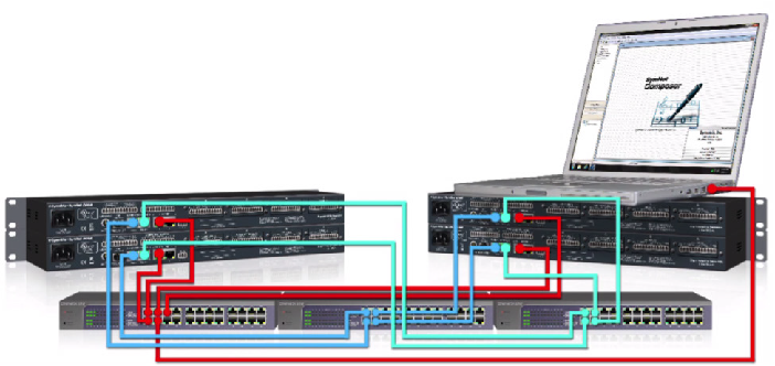
The red wires are for Ethernet/Control. The blue wires are for Primary Dante. The green wires are for Secondary Dante. Notice that each set of wires has its own network switch.
Changing from Switched Mode to Redundant Mode
To switch the Symetrix system to run Dante in “Redundant mode” when already in the default “Switched mode,” use the procedure below.
1 Cable the Dante network as if it were in “Switched mode,” not “Redundant mode.” In other words, if using an external switch or a direct connection between two units, make connections only to the primary jack. If more than two devices are used without an external switch, daisy chain from one unit’s primary to the next unit’s secondary. Do not complete the loop from the last unit back to the first unit.
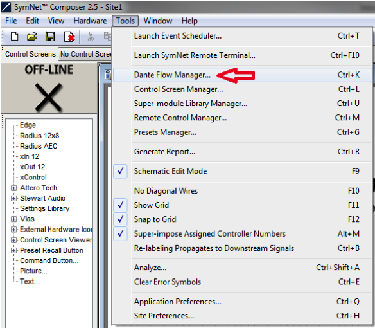
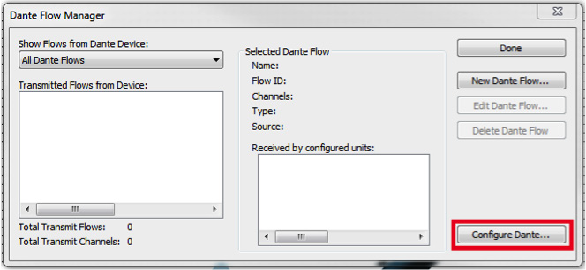
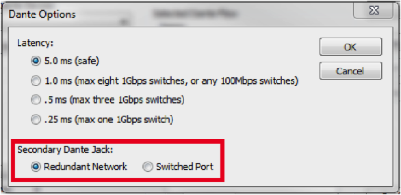
2. In Composer, go to Tools > Dante Flow Manager > Configure Dante. Select “Redundant Network.”
- Push the file and go on-line with the units. This will take slightly longer than usual as the Dante units change their mode.
- Power down the units.
- Cable the Dante network as appropriate for “Redundant mode.” Connect the primary and secondary the separate switches like the above diagram shows.
- Power on the units.
- Push the file and go on-line.
Note: Dante devices that do not support redundancy must be connected to the primary network only.
Changing Redundant Mode to Switched Mode
To switch a Composer-based system to run Dante in “Switched mode” when already in “Redundant mode,” use the procedure below.
- Power down the secondary Dante network.
- In Composer, go to Tools > Dante Flow Manager (or Tools > Network I/O Manager > Configure Dante. Select “Switched Port”.
- Push the file and go on-line with the units. This will take slightly longer than usual as the Dante units change their mode.
- Power down the units.
- Cable the Dante network as appropriate for “Switched mode.”
- Power on the units.
- Push the file and go on-line.
Dante Controller is a free software application that enables you to route audio and configure devices on a Dante network. With automatic device discovery, one-click signal routing and user-editable device and channel labels, setting up a Dante network couldn’t be easier.
Dante Controller is much more than just a configuration and routing matrix. It provides essential device status information and powerful real-time network monitoring, including device-level latency and clock stability stats, multicast bandwidth usage, and customized event logging, enabling you to quickly identify and resolve any potential network issues.
If a Composer-based Dante system is experiencing audio drop outs, appears to have disappearing units, or any other Dante audio related anomaly, using Dante Controller to gather info about the problem, network conditions, and logging of the Dante clock and network is the single most helpful tool in determining the cause and solving the issue.
In most cases, by providing Symetrix Technical Support with screen shots of the Dante Controller tabs at the time of a failure, as well as an exported log file, Symetrix support can narrow down the problem by themselves and when necessary enlist the help of Audinate engineers.
As such, it is imperative that Dante Controller be installed on a field tech’s computer. Be sure to install the latest version of Dante Controller found on Audinate’s website here:
https://www.audinate.com/products/software/dante-controller
As new releases of Dante Controller become available, Symetrix recommends upgrading to them. All methods for gathering info and logging info should be applicable regardless of the software version above Dante Controller 3.5.3.1.
How to Prepare Dante Controller to Log Events and Clock
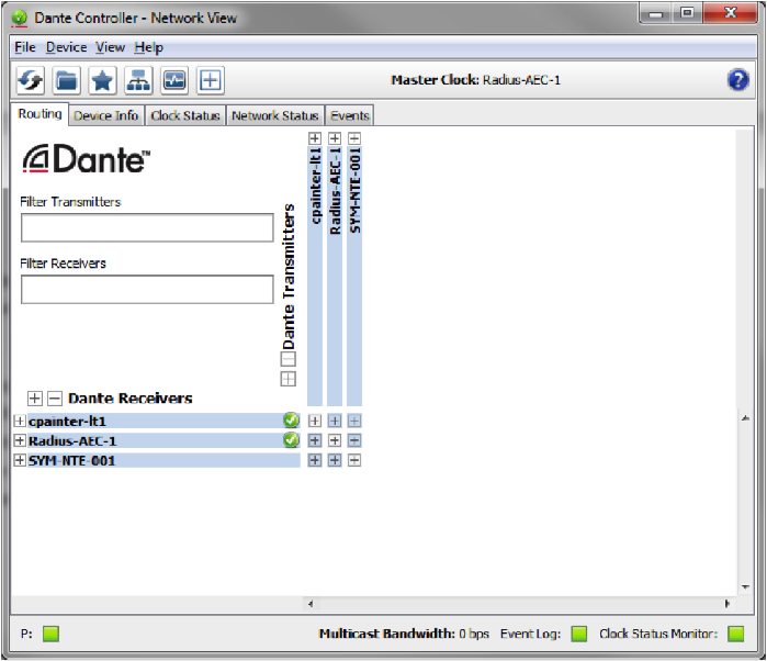
Dante Controller is easily setup for logging of events such as warning, errors, and information. In fact, much of this is done automatically when Dante Controller is simply opened and allowed to run on the same network as the Dante hardware. A LAN port on the computer running Dante Controller must be used to connect to the Dante network due to the fact that wireless network connections are not supported.
Once Dante Controller is opened, it will show the Dante hardware routing matrix and will indicate subscriptions between units on the network using green checks. If icons other than green checks are showing at the cross-points, then the icons should be investigated as they typically indicate a problem with the Dante network or device.
DC 1
However a mouse over the cross-point should cause a tooltip window to open with a message about the error or subscription status.
DC 2
In order to turn on Clock Monitoring, engage the quick button icon at the top of the software that looks like a heart monitor. Here is the actual icon for reference:
DC 3
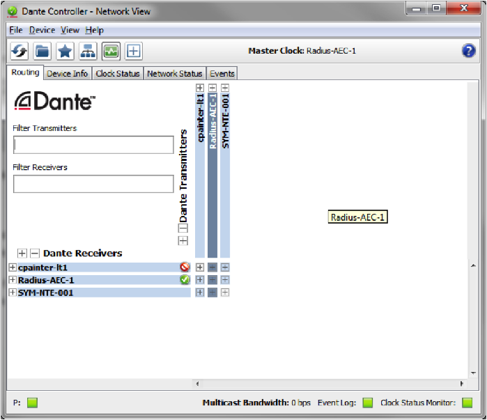
Once Clock Monitoring is engaged the button should indicate it is active with a green heart monitor icon:
DC 4
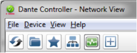
When clock monitoring is enabled the top tool icons will look like this:
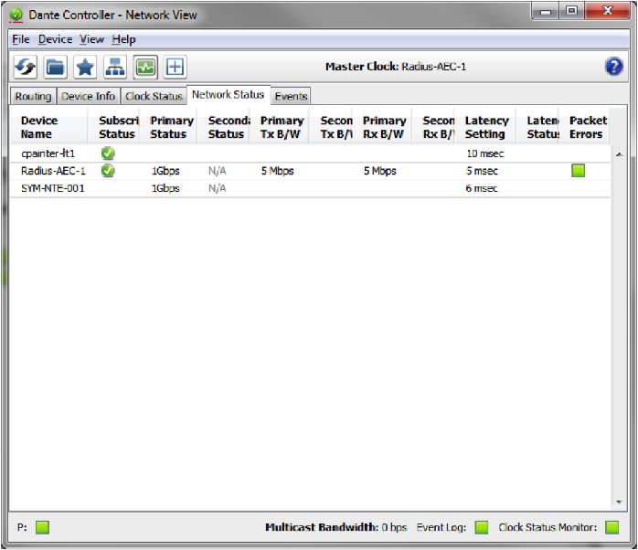
Now Dante Controller is ready to wait for the problem or audio anomaly to happen. Once the problem has resurfaced, open Dante Controller. Take screen shots of all of the 4 following tabs and email them to Symetrix support a support@symetrix.co.
Use “Alt + Prt Scr” keys to take a screen shot of the Dante Controller software. The following 4 tabs should be sent to Symetrix:
1. Routing Tab
2. Device Info Tab
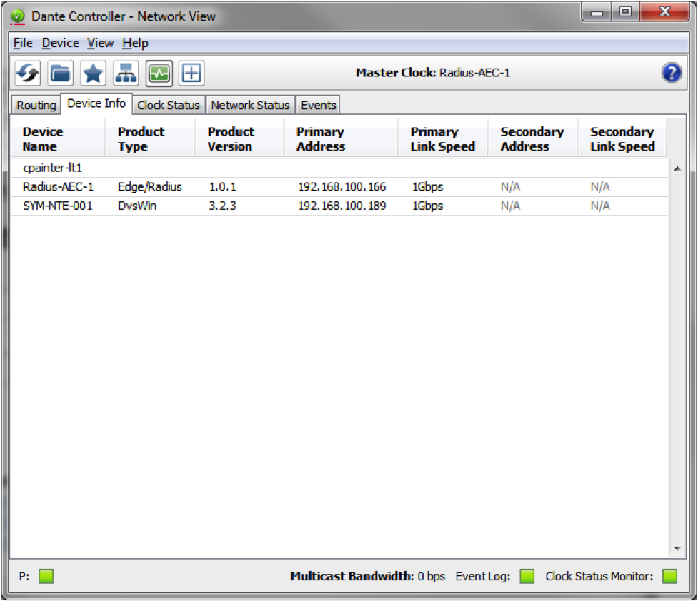
3. Clock Status Tab
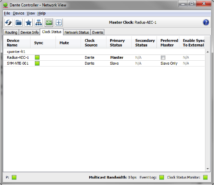
4. Network Status Tab
Lastly, Symetrix will require a copy of the log file. Open the Events tab.
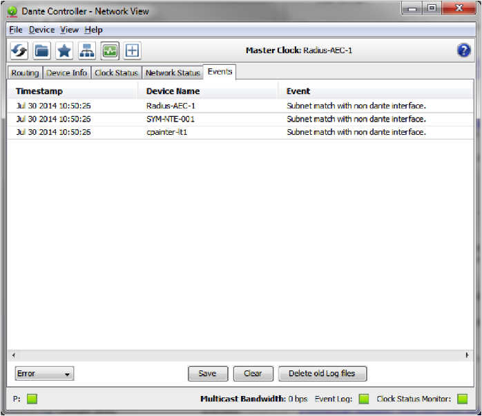
Hit the “Save” button at the bottom of the window and save the file to the computer’s desktop.
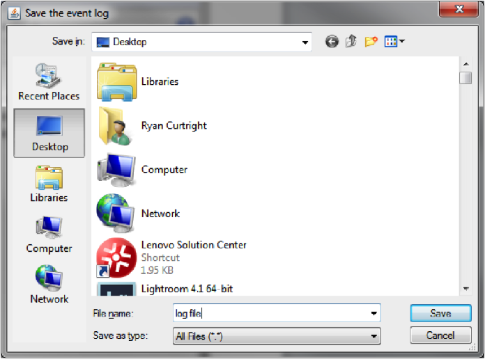
Attach the log file and all four screen shots to an email. Send them to support@symetrix.co for an evaluation of the Dante network, current state of hardware, and the log file information.
Some Symetrix equipment has the capability of taking advantage of Dante redundancy, allowing audio to continue flowing through a secondary Dante network if the primary should fail. For Symetrix systems that don’t have this redundancy capability or for systems that prefer having a fail-over to analog audio if the Dante source should fail, there is some simple logic programming that can help.
- Open up the site file and note this example has a single channel of Dante audio and a single channel of analog audio. The intention is that Dante is the primary audio source and the analog is the fail-over, or secondary source.
- From the toolkit, drag in a mono input selector from the routers and selectors, mono input selectors folder.
- Then drag in an audio peak detector from the control modules, control accessories folder.
- Next, drag in a dual preset trigger also from the control accessories folder.
- Last, pull in an inverter from the control processes folder. Wire everything as shown.
- Open up the mono input selector and name the inputs for analog and Dante.
- Then open up the audio peak detector and set the threshold to negative sixty dee-bee, and choose RMS. RMS will average out the input audio and make the detection more consistent than peak.
- Open up each preset trigger module. In the top one, make sure preset 1 is entered. Set the bottom one, involving the inverter module inline, to preset 2.
- Now, back in the mono input selector module, select input two for Dante. Right click on the slider and select “store input selector setting in preset”, and choose preset one.
- Move the slider back to the analog input, right click on the slider and store it to preset two.
And that’s all the programming needed for this.
When audio is flowing from the Dante bus, it is detected by the peak detector. If the input meets or exceeds the threshold, the peak detector outputs 100% control signal which triggers preset 1, telling the input selector to select the Dante input.
When audio is not flowing from the Dante bus, that is also detected by the peak detector. If the input drops below the threshold, the peak detector outputs 0% control signal which is then inverted to 100% control signal, triggering preset 2, telling the input selector to select the analog input.
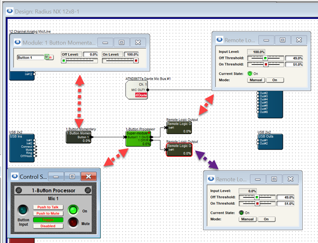
This tech tip provides a step-by-step guide on how to configure a microphone’s mute button with LED functionality using the Composer software. The instructions are applicable to microphones that have a physical mute button and an LED light to indicate whether the microphone is muted (red light) or unmuted (green light).
The process involves preparing the workspace, opening the DSP in design view, incorporating the “1-Button Processor” Super Module, adding control elements, configuring the mic button, programming the mute function, and finally activating and testing the setup.
By following these steps, you can configure the microphone’s mute button to toggle mute on/off and use the LED light to visually indicate the current status. This setup enhances the usability of the microphone, providing clear visual feedback to the user.
1 Firstly, prepare the Workspace:
- To start with, launch Composer software.
- Create a new site file or load an existing one.
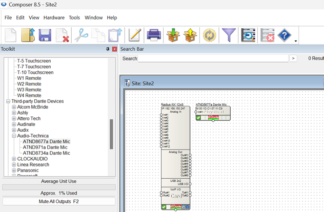
- Add the DSP (e.g., Radius NX 12×8) and microphone (e.g., ATND8677a) into the site view.
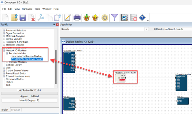
2. Next, open the DSP in design view.
- Insert the Mic Network I/O Receive Module:
- Navigate to Toolkit -> Network I/O Modules -> Receive Modules.
- Choose your mic (e.g., ATND8677a Dante Mic Bus #1) from the list.
- Link the Receive module to the desired output (e.g., Analog out 1).
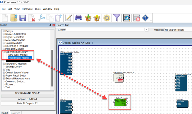
3. After that, incorporate the “1-Button Processor” Super Module:
- Go to Toolkit -> Super-module Library -> Import Super-module…
- Browse to Documents\Composer 8.5\Super-modules\examples\Tools.
- Select and add “1-Button Processor” to your design.
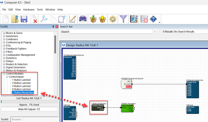
4. Subsequently, add Control Elements:
- Include a 1 Button Momentary” module:
- Find it under Toolkit -> Control Modules -> Control Inputs -> 1 Button Momentary.
- Connect this button to the 1-Button Processor” Super Module.
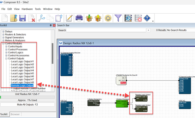
- Insert two “Remote Logic Output” modules:
- Locate them in Toolkit -> Control Modules -> Control Outputs -> Remote Logic Output.
- Connect the 1 Button Processor” to both of these modules.
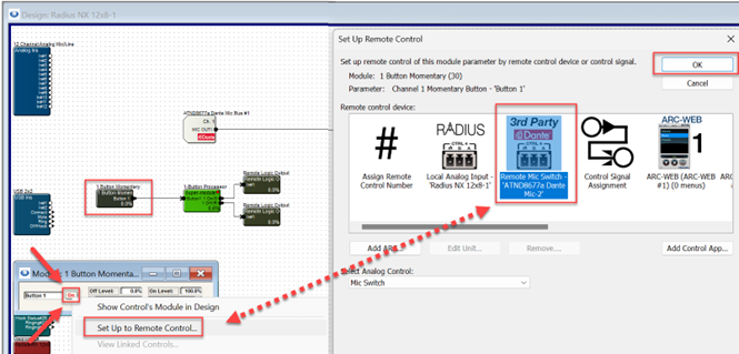
5. Once done, configure the Mic Button:
- Double-click the “1 Button Momentary” module to access its settings.
- Right-click the “On” button and choose “Set Up to Remote Control…”
- In the Remote-Control Device section, select your microphone (e.g., “ATND8677a Dante…”). Click OK.
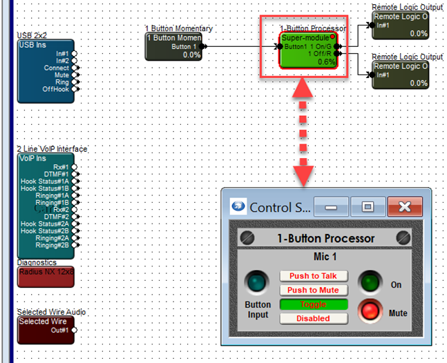
6. Afterwards, program the Mute Function:
- Double-click the “1 Button Processor” module.
- Choose the desired mute function (e.g., Toggle, Push to Talk, Push to Mute, Disabled). For this example, select “Toggle.”
7. In the end, activate and Test:
- Upload the site file to your system.
- The mic’s mute button should now function as configured, toggling mute on/off and indicating the status with red/green colors.
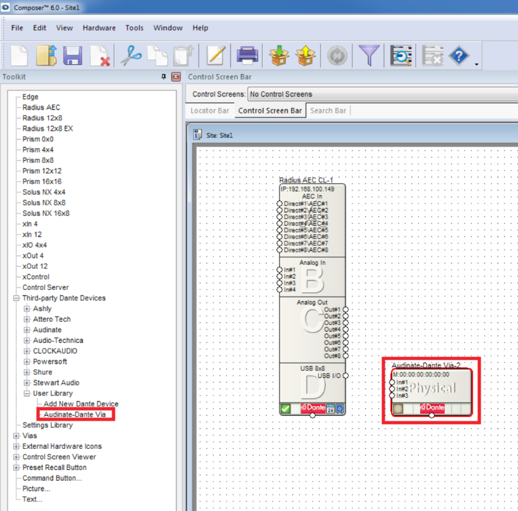
This Tech Tip is to provide instruction on how to add third-party Dante devices to the User Library of Composer. Symetrix Composer contains a list of supported third-party Dante devices. When these supported devices are added to a site file, Composer can create transmit/receive subscriptions as well as provide control for some devices.
The User Library is located in the Third-party Dante Devices section of the Toolkit in Device View. Any third-party Dante device can be added to the User Library. Once a device is added to the User Library, Composer will treat it as a supported third party Dante device. There are two methods to add a third-party Dante device to the User Library:
- Browse Dante Network
- Import XML File
Browse Dante Network
Add 1
Here are the instructions to add a third-party Dante device to the User Library by browsing the Dante network: (This example uses a Radius AEC and a Windows PC running Dante Via)
- From the Toolkit, add a Radius AEC to the Site View page.
- Next from the Toolkit, expand Third-party Dante Devices.
- Expand the User Library and add a New Dante Device to the Site View page.

Add 2
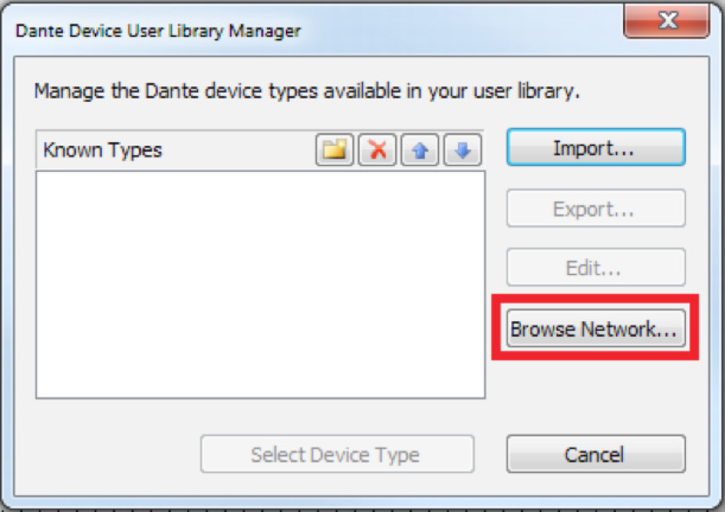
The Dante Device User Library Manager window will open.
4. Click the “Browse Network” button.
Add 3
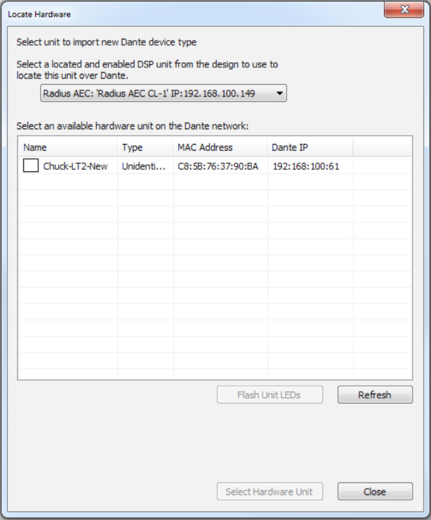
5. The Locate Hardware window will open and display all available Dante devices on that network.
Add 4
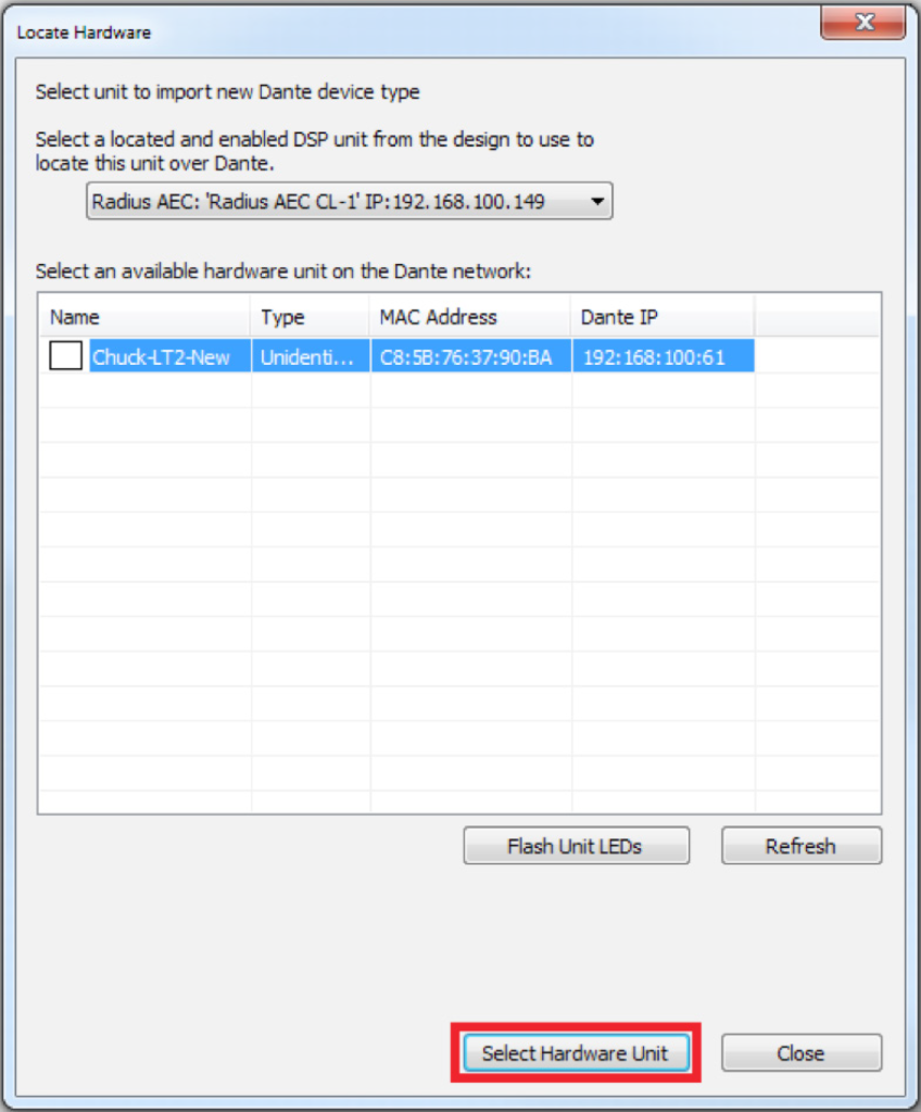
6. Select the desired Dante device, then click the “Select Hardware Unit” button.
Add 5
7. The Dante Device User Library Manager will now list that Dante device. Select the desired Dante device and click the “Select Device Type” button. This will add the device to the site view page.

Add 6
8. Once added to the library, these devices are available to add to any site file. Open the Design View page by double-clicking the Radius AEC.
Add 7
9. From the Toolkit, expand Network I/O Modules, then expand Receive Modules.
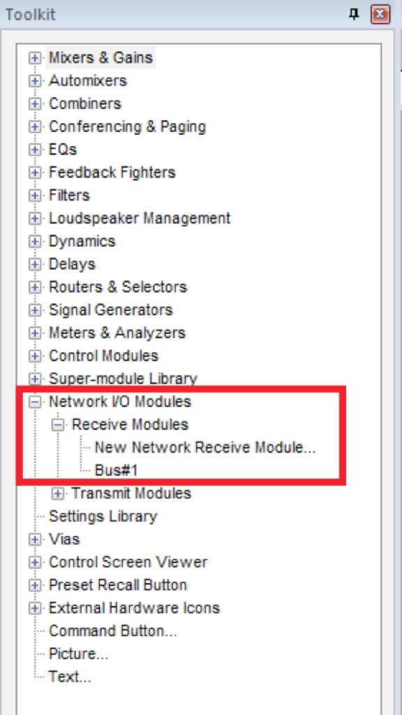
Add 8
10. Bus#1 is automatically created and available. Add Bus#1 to the Design View page.*
11. Push the site file and Composer will make the Dante subscriptions for these channels.

Import XML File
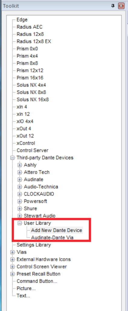
Here are the instructions to add a third-party Dante device to the User Library by importing an XML file: (This example uses a Radius AEC and a RDL DD-BN31 wall-mounted Dante interface)
- From the Toolkit, expand Third-party Dante Devices.
- Expand the User Library and add a New Dante Device to the Site View page.
The Dante Device User Library Manager window will open.
Add 9
Here are the instructions to add a third-party Dante device to the User Library by importing an XML file: (This example uses a Radius AEC and a RDL DD-BN31 wall-mounted Dante interface)
- From the Toolkit, expand Third-party Dante Devices.
- Expand the User Library and add a New Dante Device to the Site View page.
The Dante Device User Library Manager window will open.
Add 10
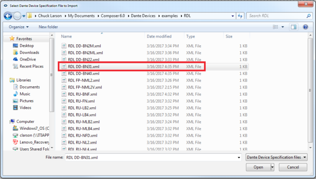
3. Click the “Import” button.

Add 11
4. Navigate to the XML file to be imported.
5. Select the XML file, click “Open.”
Add 12
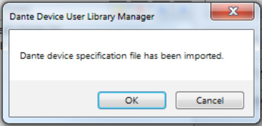
6. Click OK when the Select Dante Device Specification File to Import window opens, confirming the file has been imported.
The RDL DD-BN31 device is now available from the User Library.
Add 13
7. Select the device from the list of Known Types; click the “Select Device Type” button.
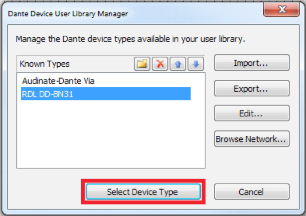
Ad 14
The RDL DD-BN31 will be added to the site file and is now available from the Toolkit.

Add 15
8. From the Toolkit, add a Radius AEC to the Site View page.
9. Open the Design View page by double-clicking the Radius AEC.
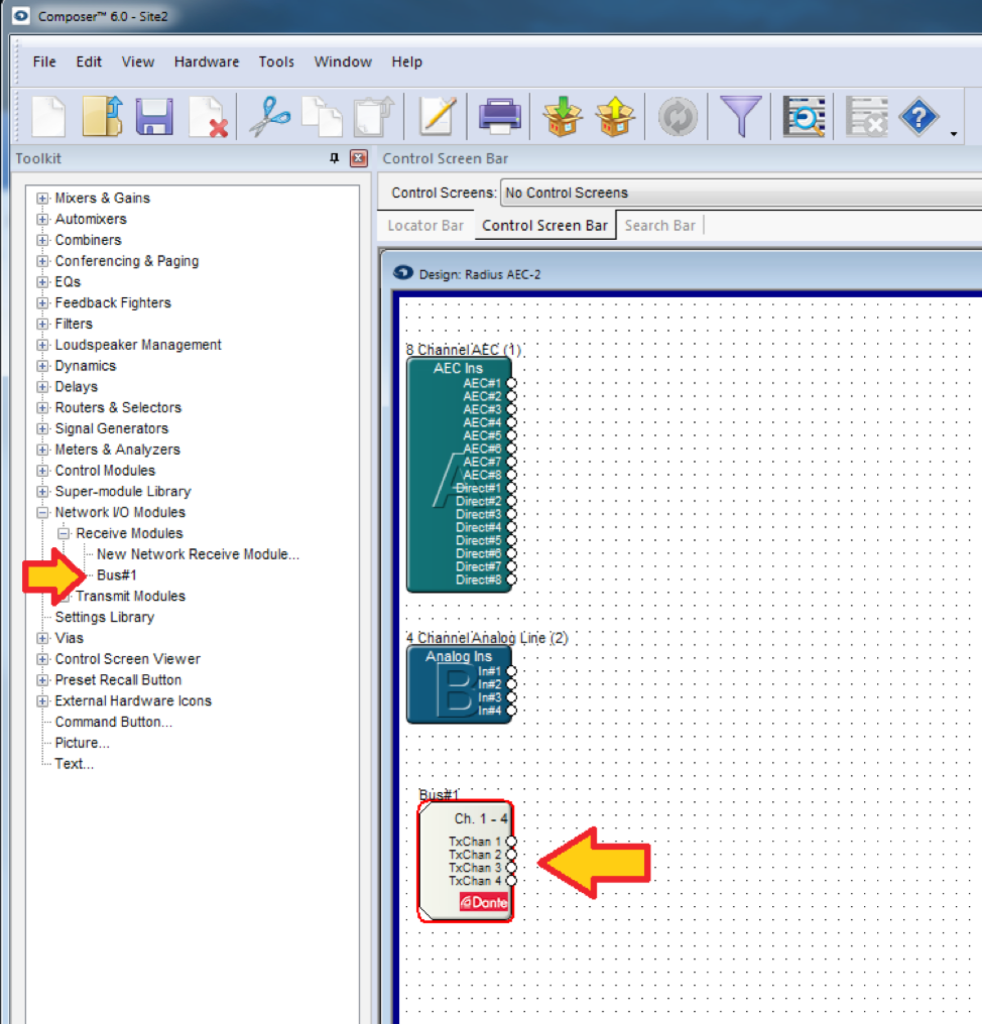
10. From the Toolkit, expand Network I/O Modules, then expand Receive Modules.
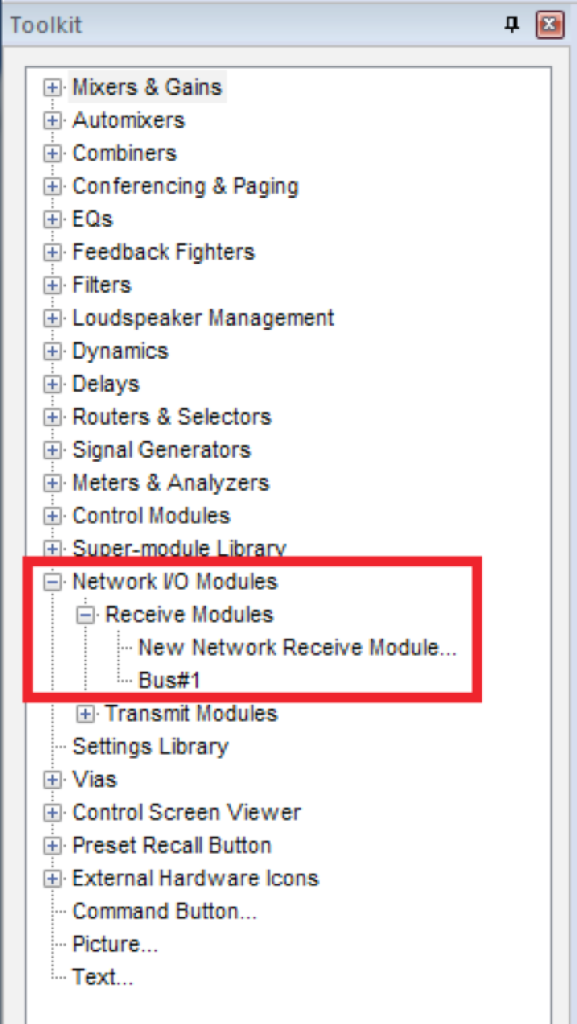
Add 15
11. Bus#1 is automatically created and available. Add Bus#1 to the Design View page.*
12. Push the site file and Composer will make the Dante subscriptions for these channels.
*Whenever a Symetrix Dante-enabled Analog I/O Expander, third-party Dante device, or transmit bus are added to a site file, a receive bus is automatically created, and available from the Toolkit.
Introduction
This guide covers usage of Composer and Dante Domain Manager (DDM), exploring crucial do’s and don’ts. This resource aims to optimize your experience with these powerful tools for managing your audio network. While DDM is supported in past Composer releases, it is highly suggested that when using DDM with Composer, to always use the most recent version of Composer. At the time of this writing the most recent DDM compatible version is Composer 8.5.1.
Dante Domain Manager Operation
- Pushing Site Files: When planning to utilize DDM, it should be ensured that the system is working properly before enrolling the devices in DDM. This includes ensuring device firmware is up to date. All Dante routing and utilization of Intelligent Module controls on SymVue screens be completed and pushed before enrollment. After enrolling devices into DDM, changes to Intelligent Modules and Dante routing will not be accessible without removing devices from the Domain and rebooting the DSP. This is due to some of the limitations on Dante Device locating under DDM.
- Device Enrollment: After ensuring the system is in working order and Dante routes are as planned, enroll the devices into DDM using the same process as any other system. All devices in a Site File should be in the same domain. See Known Issues in 8.5.1 (8).
- Enrollment Sequence: If devices are enrolled prior to initiating the ‘Push Site File’ operation, the ‘push’ functionality will fail as the Dante devices are no longer located in Composer. To correct this, un-enroll the devices from the domain, reboot the DSPs, push the completed Site File, and re-enroll the devices.
- Adjustments to Site Files: If modifications to the Site File or DSP firmware are needed, it is essential to un-enroll devices before proceeding and if needed, reboot the DSP to locate non-DSP Dante devices. This step ensures smooth incorporation of changes without disruptions to Composer-Dante communications. Then, make the changes, push to ensure correct functionality, and re-enroll the devices into the Domain.
Dante Director
Similar operation has been observed while using Composer with Dante Director. Any steps taken to use Composer with DDM can and should be applied when enrolling devices into Dante Director.
Operational Notes Using Composer 8.5.1 or Later
- Clock Leader in Dante Controller: When combining Brooklyn 2 and Brooklyn 3 cards in the same domain, a Brooklyn 2 card will show as Primary v1 Multicast Leader and a Brooklyn 3 card will show as Primary v2 Multicast Leader in Dante Controller. This issue can be corrected by selecting a Brooklyn 2 card device as the preferred leader.
- Clock Leader in DDM: When combining Brooklyn 2 and Brooklyn 3 cards in the same domain, Dante Domain Manager will report “There are multiple (2) grandmaster devices.”
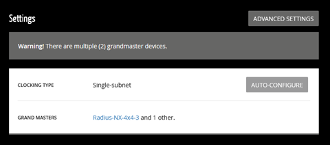
This issue can be corrected by enabling unicast clocking in the domain showing the error, once enabled, you can disable unicast clocking and the error should go away.
Both solutions (1) and (2) must be performed after the system is rebooted and each subsequent time the system is rebooted. It should be noted that although these errors are reported, there has been no reported loss of audio or control because of these errors.
- Firmware: It is not recommended to upgrade or downgrade firmware while devices are in a domain. If a firmware change happens while devices are enrolled into a domain and there are communication errors between Composer and devices, removing the device from the domain and rebooting the device should fix the communication issues. If there are still issues, attempt the firmware upgrade again.
- Stopping DDM Service: It is not recommended to stop the DDM service while devices are enrolled in a domain, stopping the DDM service can result in communication issues between Composer and the devices in the domain.
- AES-67: AES-67 is not supported when in a domain. It creates issues when a device is enrolled/unenrolled.
- Locking: Monitoring Dante device lock state from Composer is not supported for device enrolled in a domain.
Pushing: Pushing a Composer Site File is not supported while devices are enrolled into a domain.
If attempting to push you will be presented with this error. Unenroll devices prior to pushing and re-enroll the devices after pushing is completed.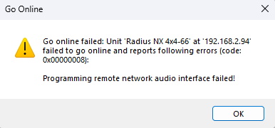
- Locating in Composer: Enrolling Devices into a domain will cause non-DSP Dante devices to fail to locate. Note, after enrolling devices into a domain, non-DSP Dante devices will not locate in the Composer site view. Audio will still pass through the network but if needed, rebooting the locating DSP will show that the devices are in fact located.
Operational Notes Using Versions of Composer Prior to 8.5.1:
- Dante Device Location: Instances have been observed where Dante devices, initially located within Composer, fail to maintain their location after enrollment into a designated domain.
- Upgrading Challenges: Migrating from Composer 8.3 to either Composer 8.4 or Composer 8.5 could potentially lead to a situation where the DSP fails to acknowledge the presence of its Brooklyn card.
- DDM Service Impact: Stopping the Dante Domain Manager service can trigger a scenario wherein the DSP ceases to identify its associated Brooklyn card, a pivotal component of the system’s functionality.
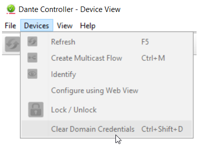
All three issues can result in the DSP not recognizing its Brooklyn card. If this is the case for you, isolating the device on the Dante network and clearing the Dante Domain Credentials can help re-establish communication with the Brooklyn card..
Composer Configuration for Sharing Audio Between Domains
It is possible, should the situation arise, to route audio from one domain to another. Follow Audinate’s suggested steps to configure shared audio groups.
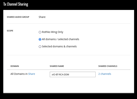
In Composer, route audio and push the Site File before adding the devices to a domain, as discussed earlier in this document. Take note of the TX and RX channels that are being used prior to push.
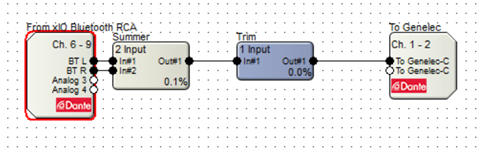
Note that the Dante “From xIO Bluetooth RCA” is using the DSP’s RX Dante channels 6-9 (Named BT L, BT R, Analog 3, and Analog 4) and that the “To Genelec” Dante bus is using the DSP’s TX Dante channels 1-2 (Named To Genelec-C and To Genelec-C).
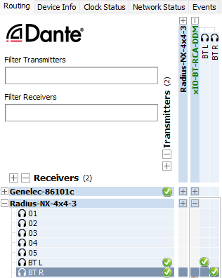
After configuring shared audio groups in DDM, the shared Dante channels will appear in the configured Dante domains, highlighted in green in Dante Controller. You may need to reroute the audio in Dante Controller.
The purpose of this Tech Tip is to provide instructions on using Dante’s Device Lock feature with Symetrix Dante-enabled hardware in Composer 6.0 or later. Device Lock allows you to lock and unlock supported Dante devices using a 4-digit PIN (Personal Identification Number) in Dante Controller. Audinate’s Dante Controller software must be used to lock and unlock Symetrix Dante-enabled hardware. They CANNOT be locked or unlocked using Composer. When a device is locked, audio will continue to flow according to its existing subscriptions, and it may be monitored, but it cannot be controlled or configured. Its subscriptions and configuration settings become read-only.
Dante Controller: https://audinate.com/products/software/dante-controller
Lock Status Indication
Symetrix Composer
In Composer, Site View will show the lock state of all Dante equipped units via the Dante Logo at the bottom center of the unit’s icon. That icon will be one of three
colors indicating ‘Dante Locked’, ‘Dante Unlocked’, and ‘Dante Lock Feature Unavailable’.
lock 1

Locked: Yellow
lock 2

Unlocked: Green
lock 3

Feature Unavailable: Red
Dante Controller
There are multiple locations within Dante Controller where the lock status of a device may be found.
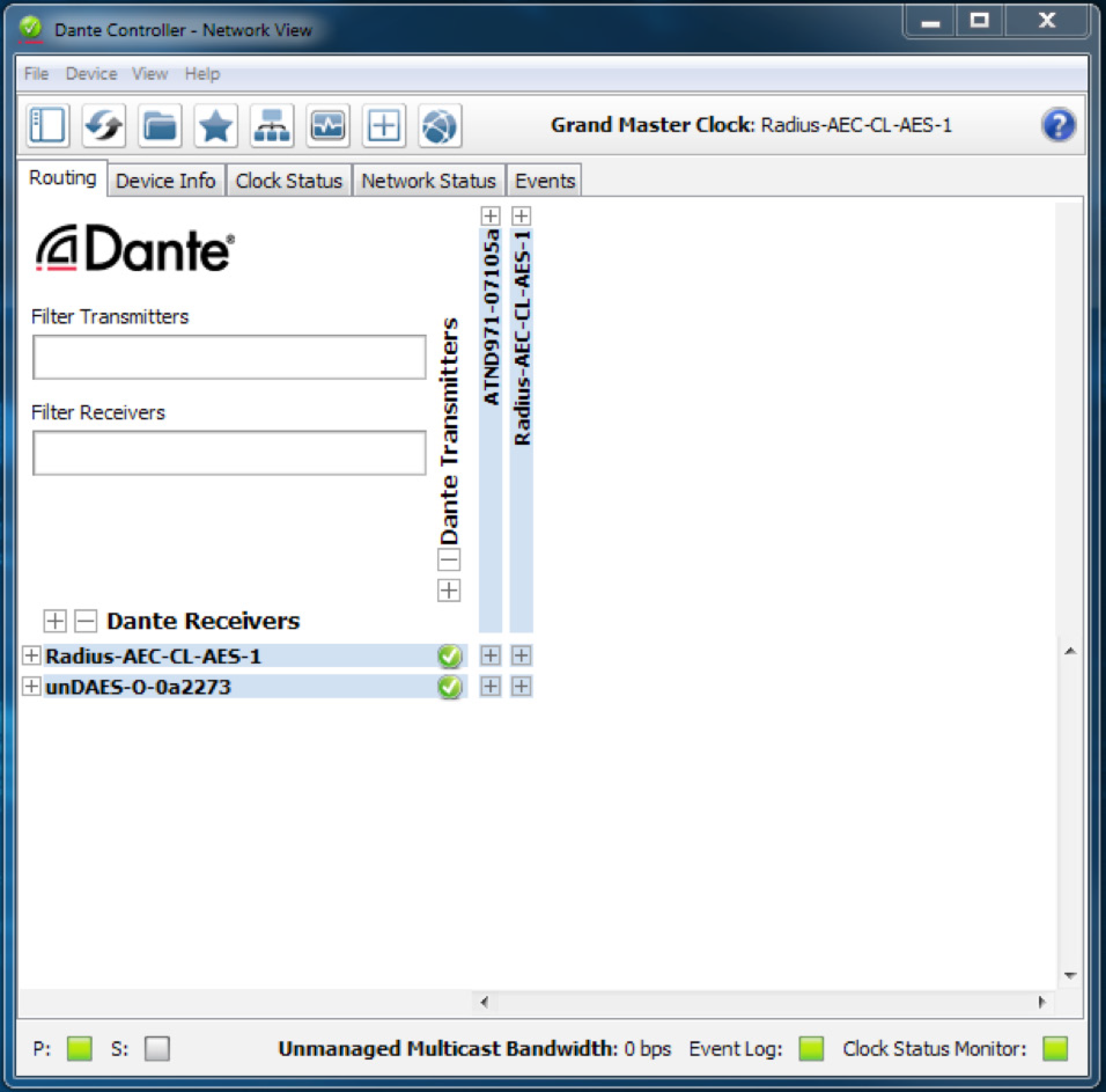
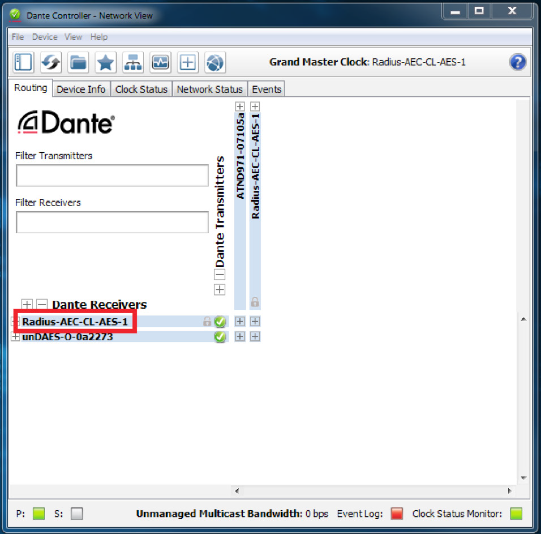
• A small gray lock icon against the device name in the Network View > Routing tab.
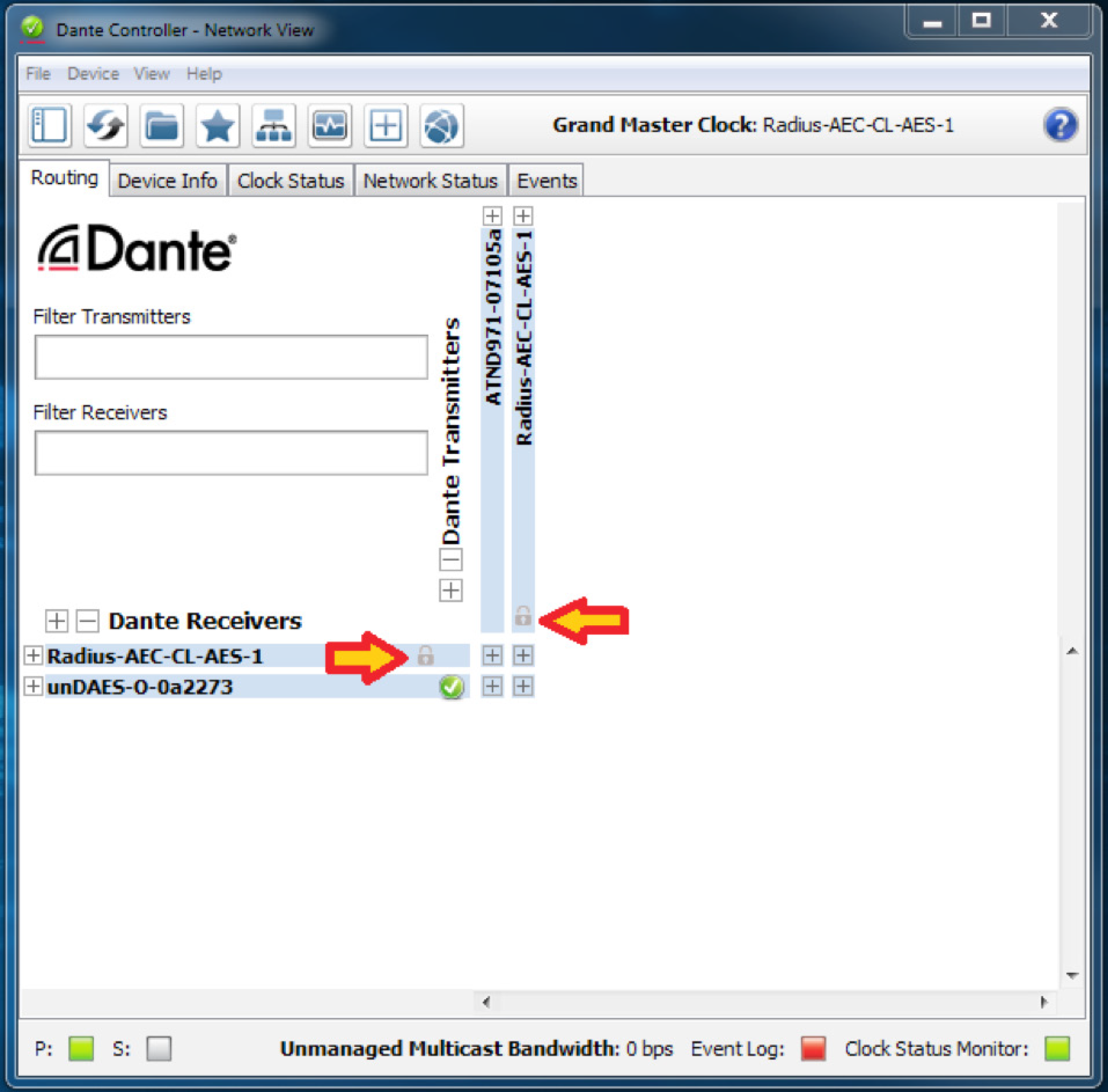
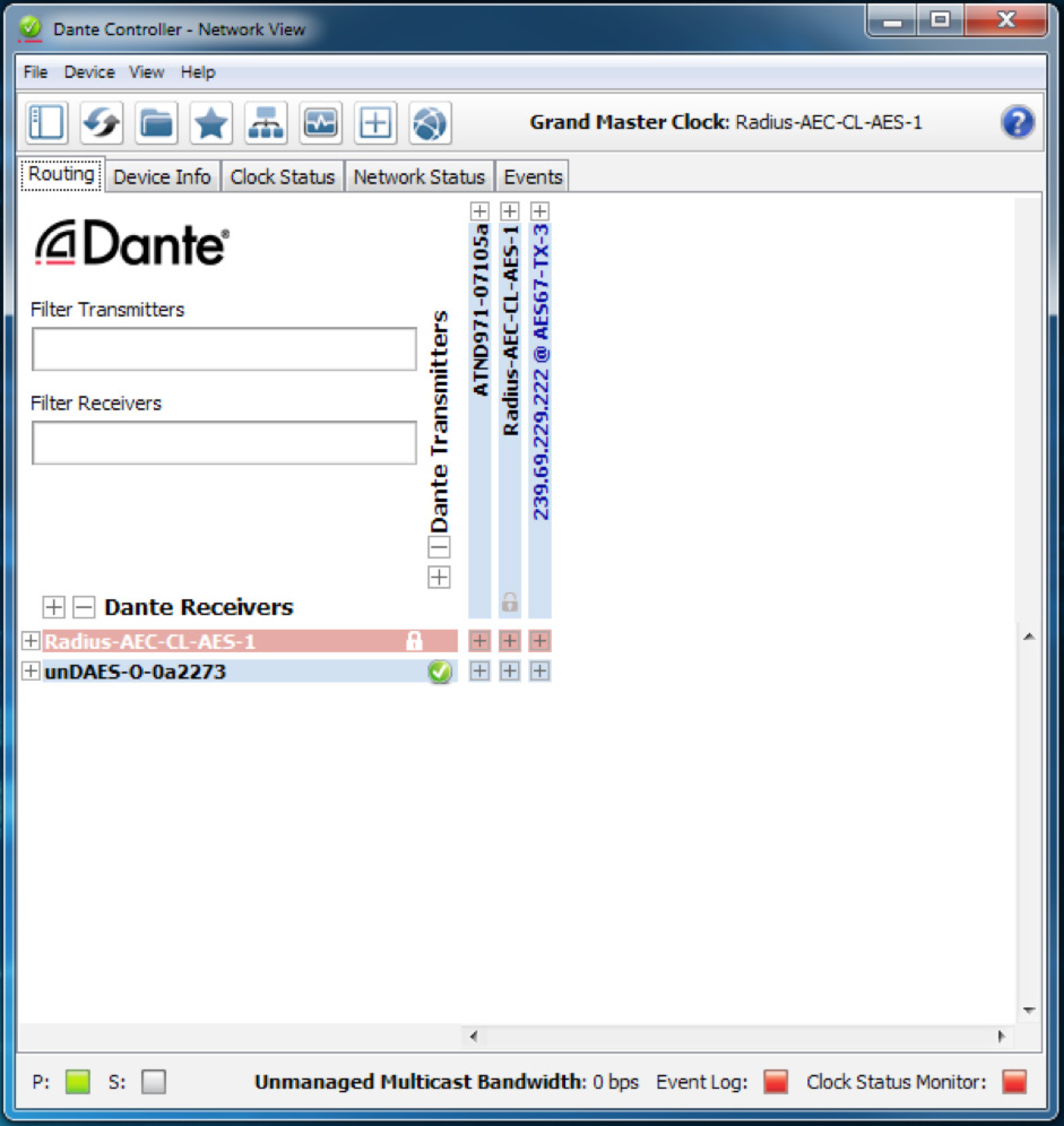
• Red background when the device is hovered over in the Network View > Routing tab.
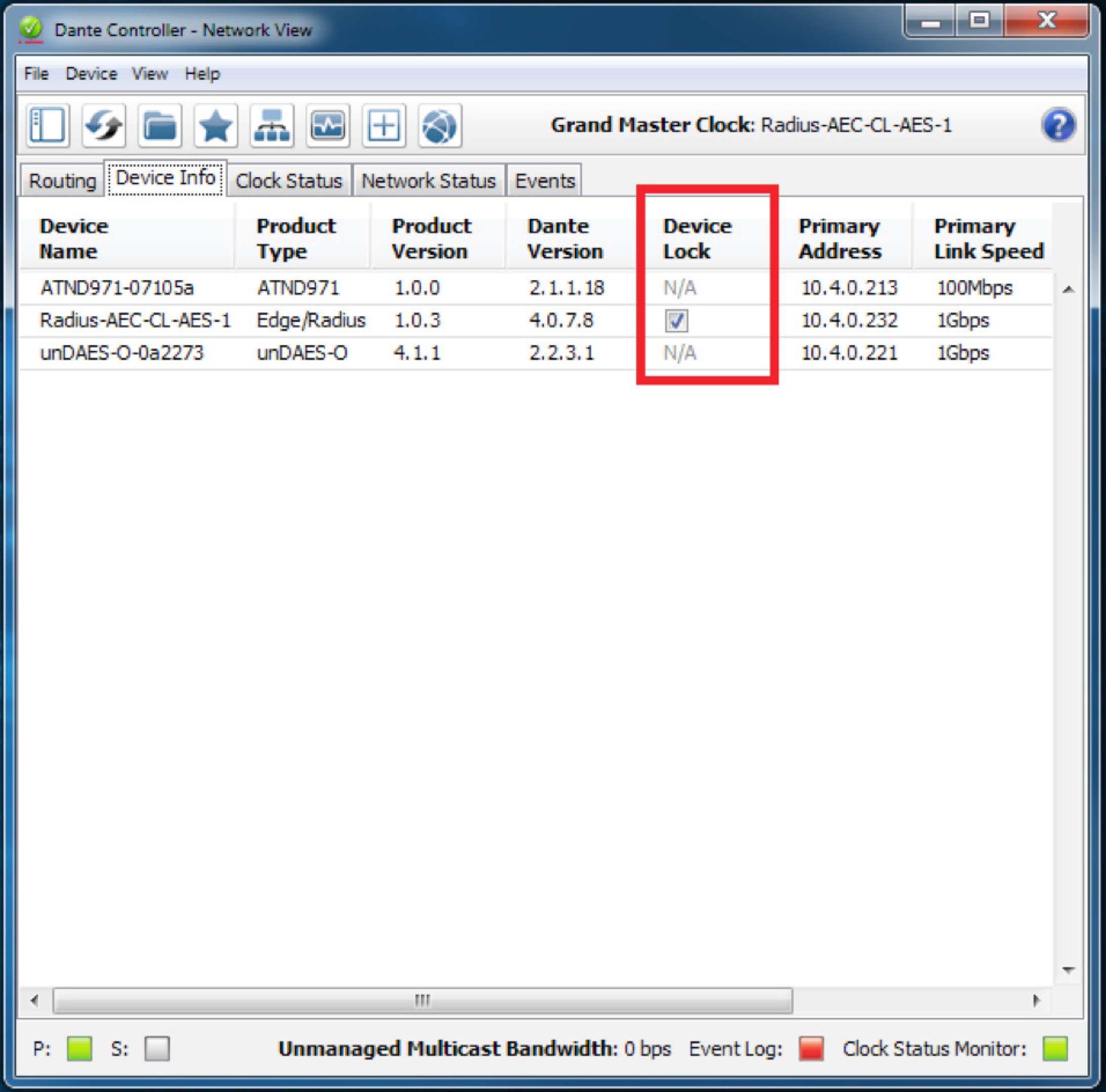
• A check in the Device Lock column in the Network View > Device Info tab.
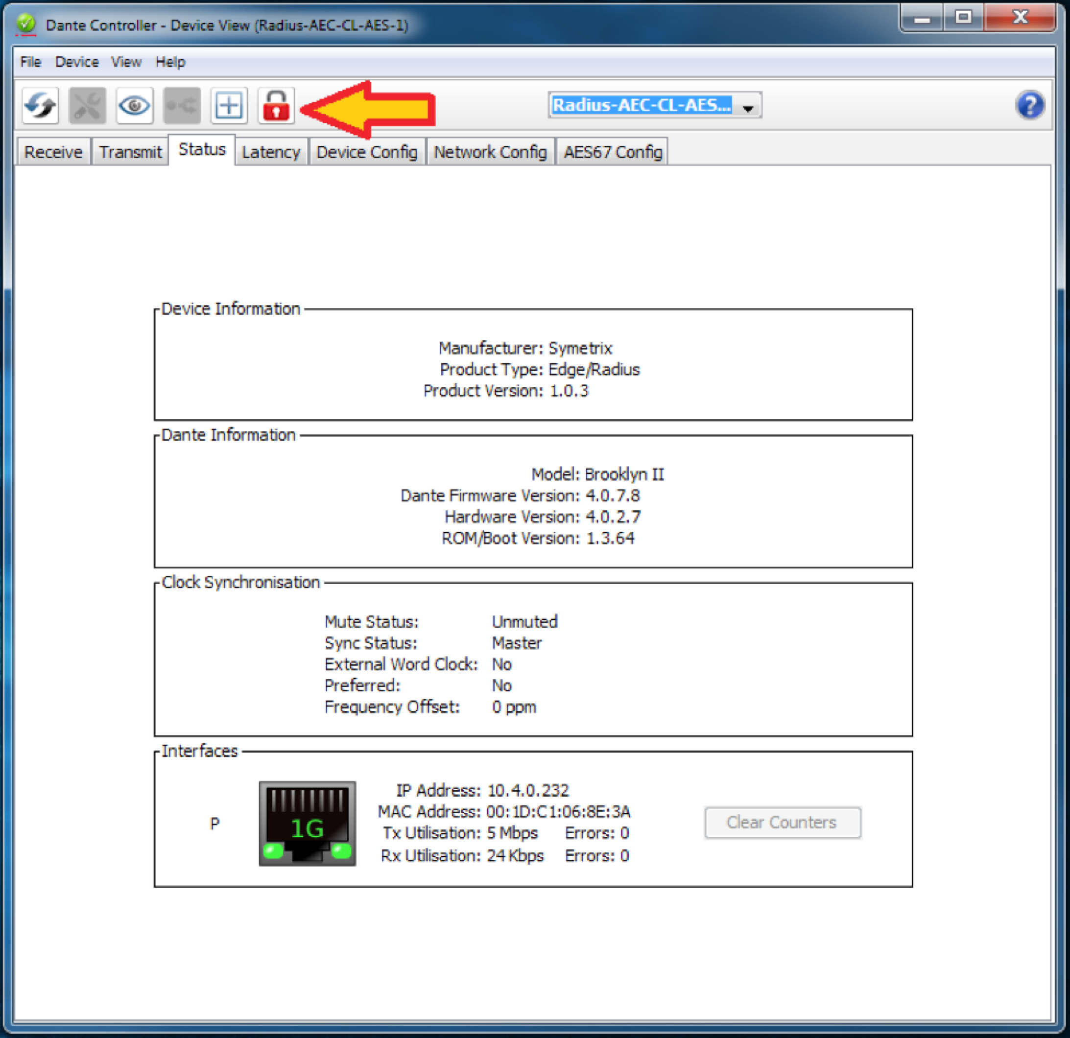
• A red lock icon in the Device View toolbar.
Lock Symetrix Dante-enabled Hardware
There are two different locations (Network View and Device View) to lock a Dante device in Dante Controller.
Network View
1. Open Dante Controller.
Note: Dante Controller opens to the Routing tab of the Network View page.

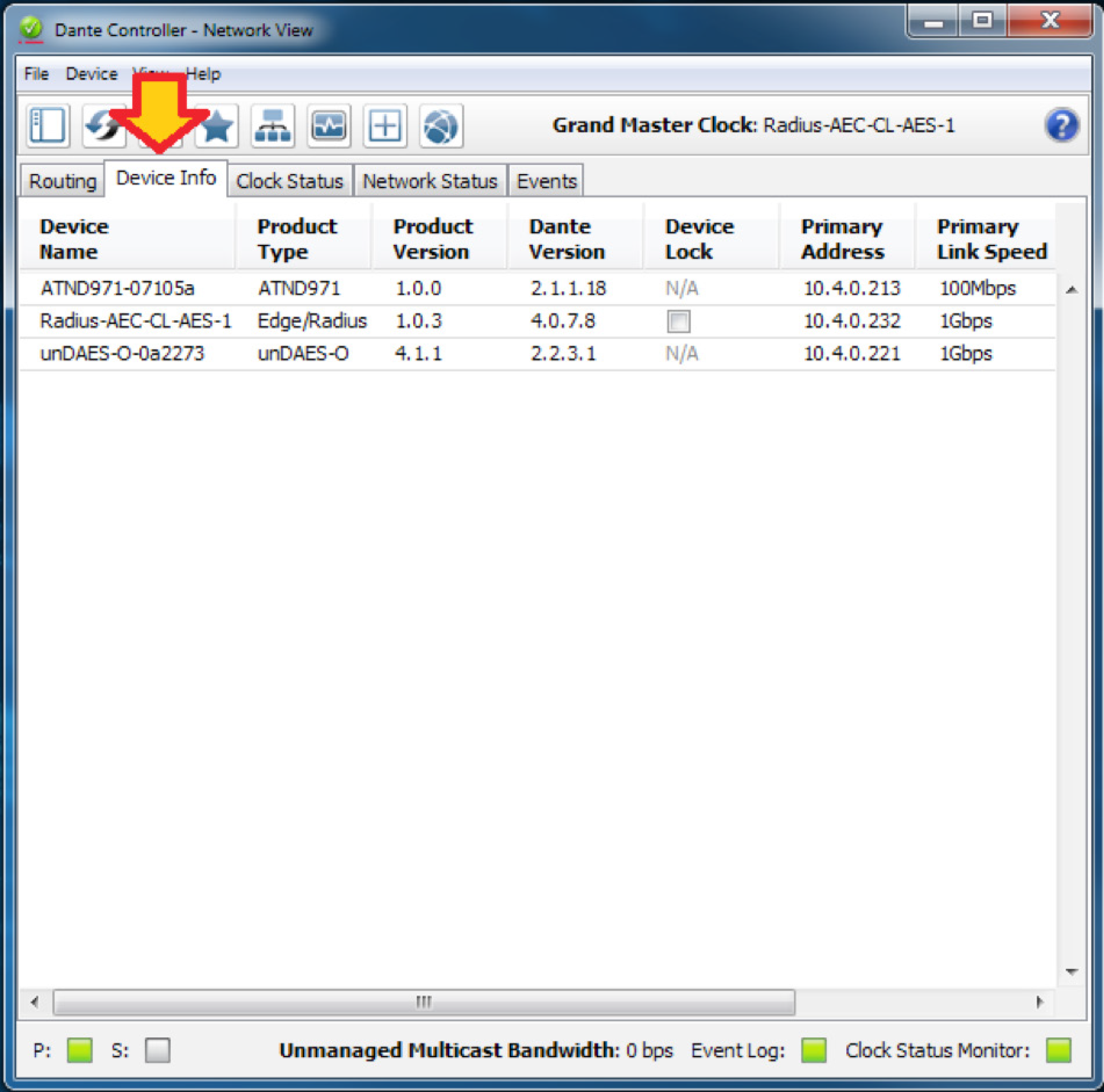
2. Click on the Device Info tab.
3. Click the box in the Device Lock column.
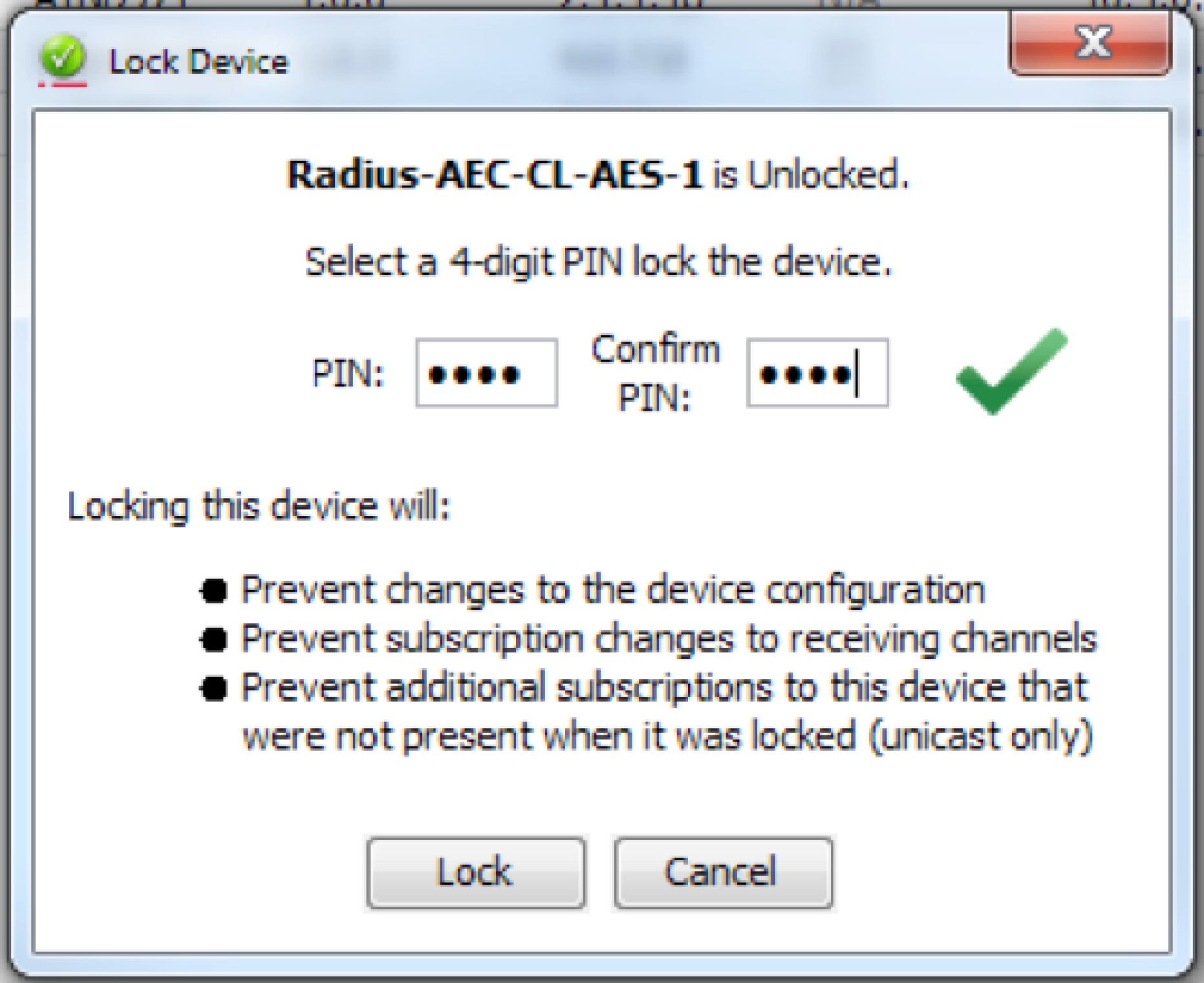
4. Enter and confirm a 4-digit PIN.

5. Click the “Lock” button. The check appears in the box to confirm the device in now locked.

Device View
1. Open Dante Controller.
Note: Dante Controller opens to the Routing tab of the Network View page.

2. Double-click the device name of the device to be locked

3. Click the lock icon.
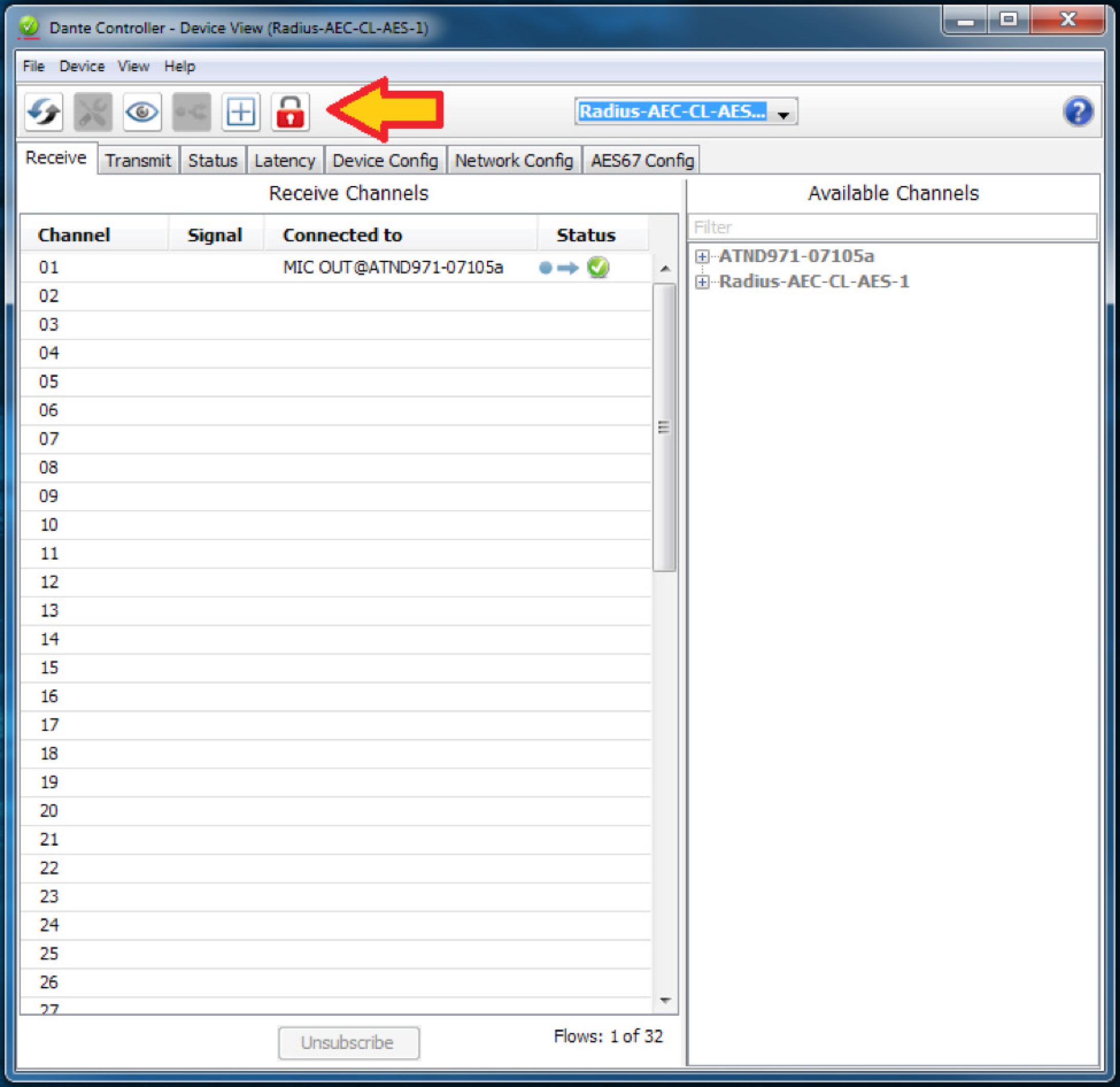
4. Enter and confirm a 4-digit PIN, then click the “Lock” button.
5. The lock icon will turn red to indicate the device is locked.

Unlock Symetrix Dante-enabled Hardware
There are two different locations (Network View and Device View) to unlock a device in Dante Controller.
Network View
1. Open Dante Controller.
Note: Dante Controller opens to the Routing tab of the Network View page.
2. Click on the Device Info tab.

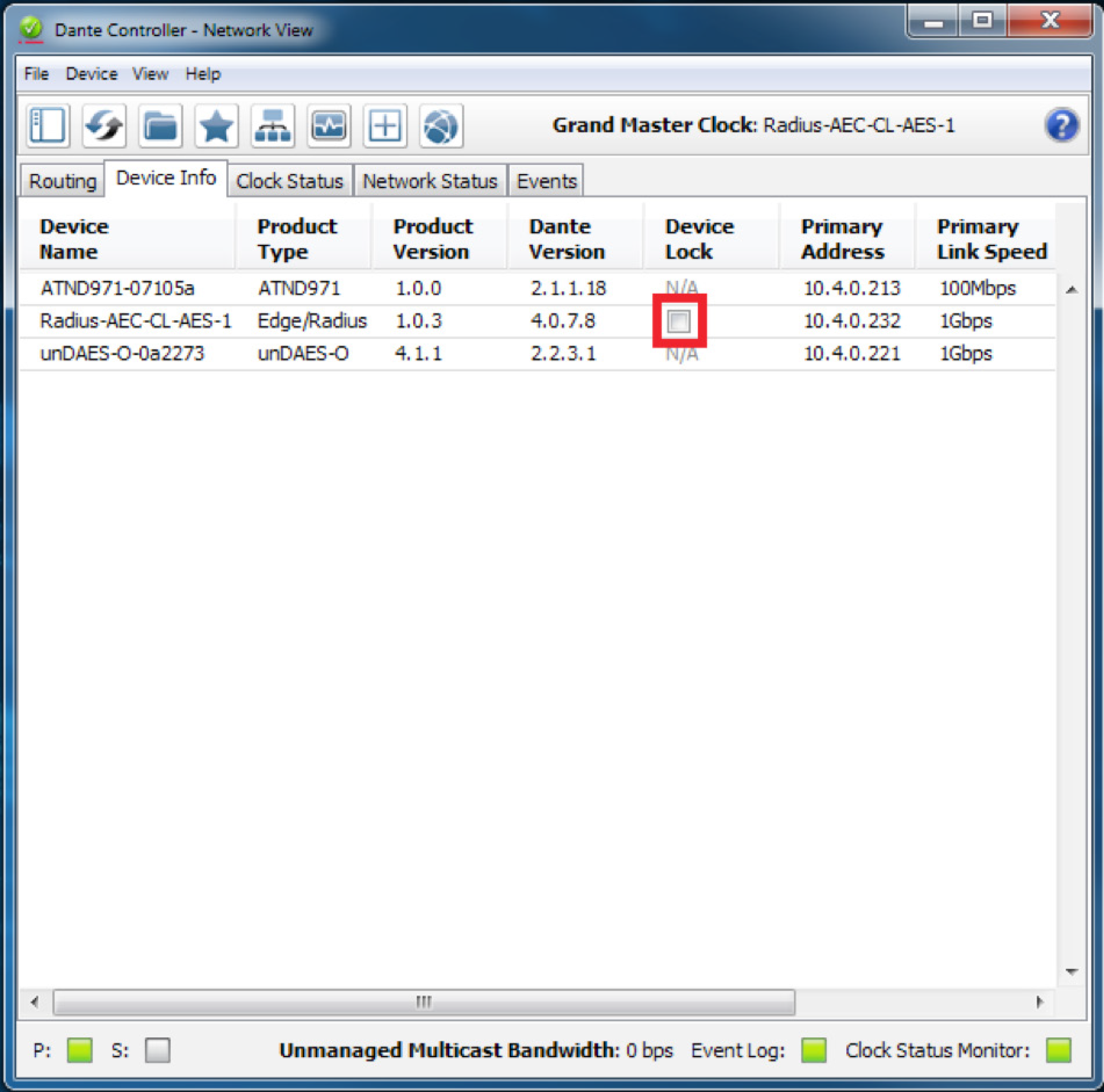
3. Click the check box in the Device Lock column.

4. Enter the 4-digit PIN, then click the “Unlock” button.
5. The check has been removed from the box to confirm the device in now unlocked.

Device View
1. Open Dante Controller.
Note: Dante Controller opens to the Routing tab of the Network View page.

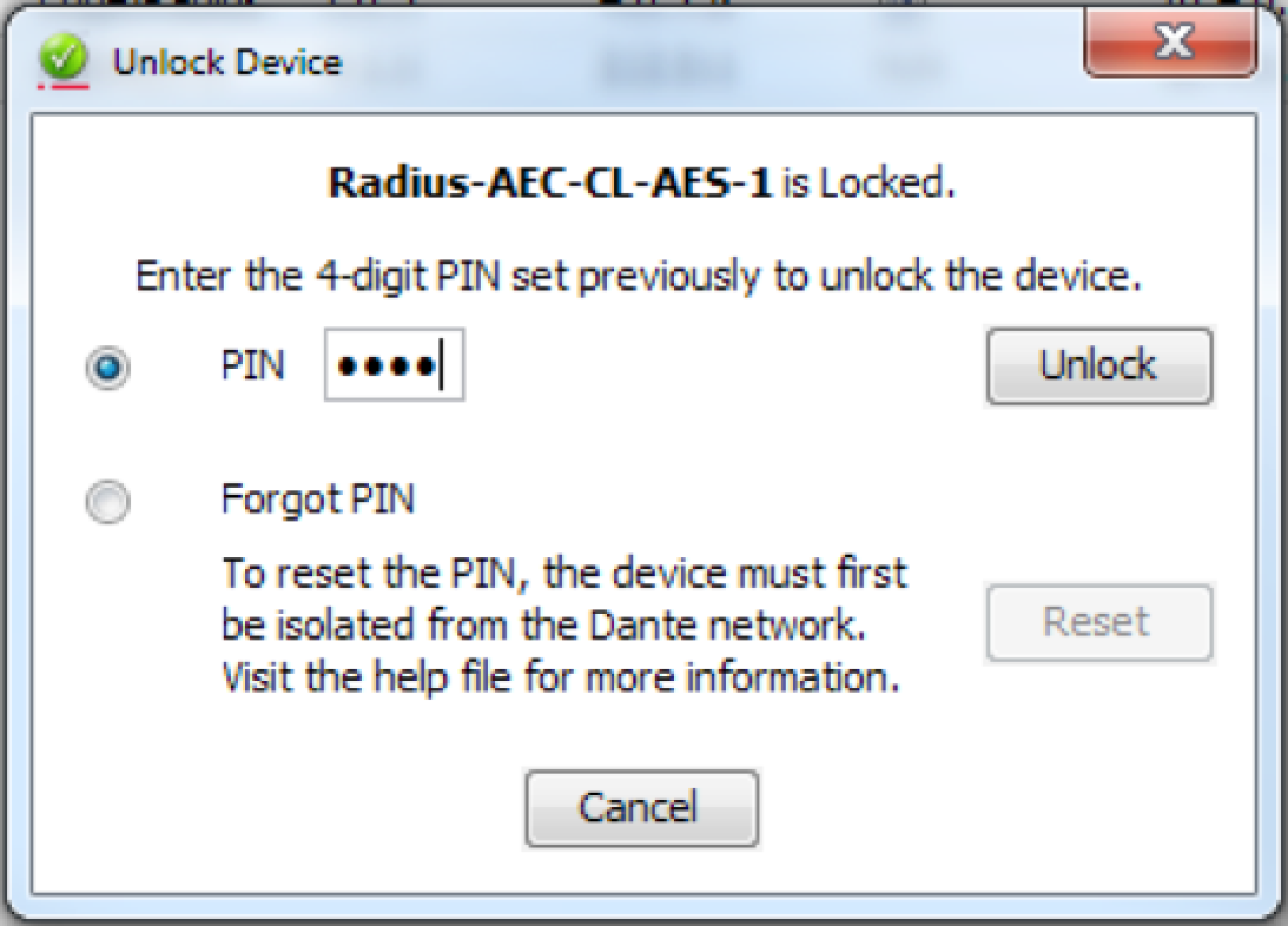
2. Double-click the device name of the device to be unlocked.
3. Click the lock icon.

4. Enter the 4-digit PIN, then click the “Unlock” button.

5. The lock icon is no longer red, indicating that the device is unlocked.
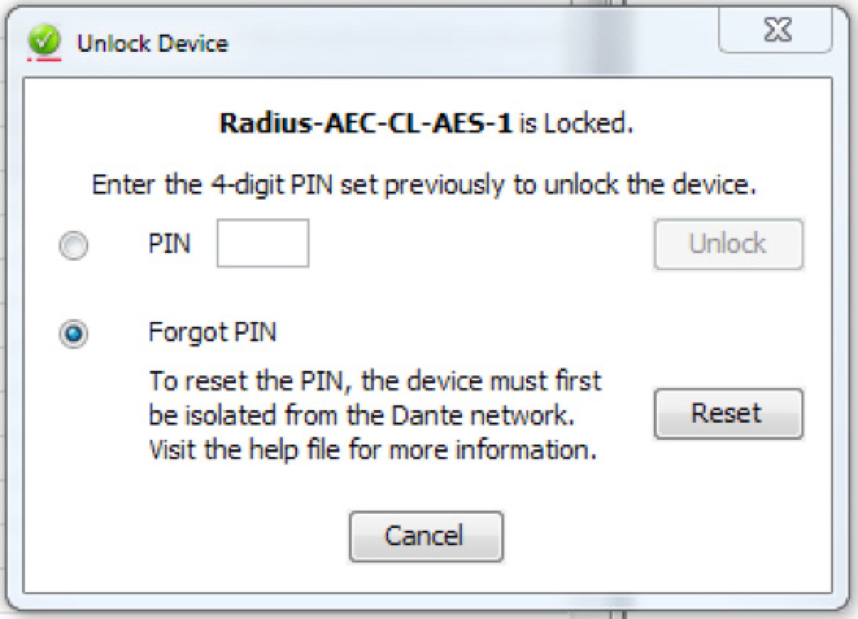
Forgot PIN
A forgotten PIN may be reset in order to access a locked device. The instructions must be followed very carefully, or the process will fail.
1. Isolate the device from the rest of the Dante network.
2. Disconnect and reconnect the device.
3. Wait for at least 2 minutes, then open the Unlock Device window.
4. Use the ‘Forgot PIN’ option in the Unlock Device window.
Overview
This tech tip will explain how to integrate the Visionary Solutions Duet Encoders/ Decoders into your Symetrix installation. The Visionary Solutions devices allow for moving 4K video over IP, bypassing the need for more traditional video matrix switching or video wall creation. The encoders and decoders come in two flavors: the Dante-enabled Duet devices (DuetE/D), and the non-Dante devices (E4100/D4100)
Using Symetrix DSPs along with Visionary Solutions’ Dante-enabled devices allows for total control of both the Dante audio and the video routing from one central device. For the non-Dante-enabled devices, Symetrix DSPs are able to control video source selection at the decoder, along with whatever audio is riding along with the AV Stream.
Before we go into working with controlling these devices from Composer, it is of paramount importance to look into the networking requirements and connections. In fact, it is highly recommended that you not connect any encoders or decoders to a switch until the below switch settings have been enabled.
Networking Requirements Switches Capabilities:
- Managed, with PoE (Visionary Solutions devices require full 15.4W PoE per port).
- Non-blocking.
- Minimum 1GbE bandwidth.
- Capable of IGMP (with IMGP Snooping).
- 8K or better Jumbo Packet capability.
Switch Settings:
- 2 VLANs – One for Video and Control traffic, the other for Dante traffic.
- Multicast must be allowed on all network ports through which video passes. DSP Ethernet ports will also need to be on this VLAN – multicast is not necessary on these ports.
- Flow Control must be removed on any network ports used for video streams.
- IGMP (Internet Group Membership Protocol): Video traffic from these devices is multicast, meaning it is broadcast across the network from a single device to all devices on the network – whether those devices want it or not. This can lead to wasted network bandwidth, as well as the potential for certain devices to be flooded. Enabling IGMP ensures that the multicast packets will only be received by those devices that are intentionally a part of that Group Membership.
- IGMP Snooping and Querier must be enabled (set Querier Version to V2 if possible).
- Enable IGMP Snooping Fast Leave: If your switch supports IGMP Snooping Fast Leave, turn it on. This lessens the amount of time it takes for a device to leave a multicast group and join another – thus speeding up the video switching time.
- Enable Jumbo Frames.
- Disable Energy Efficient Ethernet (Green Ethernet).
Cisco SG300 Example:
Two VLANs will need to be created – one for Video and Control traffic, and another for Dante traffic:
Tie the appropriate physical ports to each VLAN. In this case the first 5 physical ports will be assigned VLAN 2 (Video and Control), and the following 4 will be assigned to
VLAN 3 (Dante traffic).
For IGMP Snooping to function on the SG300, Bridge Multicast Filtering must be enabled:
Edit the Video+Control VLAN and enable IGMP Snooping Status, Immediate Leave, and IGMP Querier Status. Set Querier Version to V2.
Enable IGMP Snooping and Querier:
Enable Jumbo Frames:
Finally, disable Energy Efficient Ethernet (Green Ethernet):
VLAN 2: (Dante traffic):
- Multicast should be allowed to pass on all Dante network ports in order to allow
multicast clock packets to pass unimpeded. - IGMP is only needed if there is multicast Dante audio.
- Note that QoS is not needed on a Dante-only network
- Energy Efficient Ethernet (Green Ethernet) should be disabled.
Now that the switch has been configured properly, here is a basic connection
diagram, showing 2 encoders and 1 decoder, along with a Radius NX 12×8 DSP. The
Visionary Solutions devices’ PoE LAN ports connect to VLAN 1, and their Dante ports
to VLAN 2. The Radius NX 12×8’s Ethernet port is connected to VLAN 1, and one of
its Dante ports connects to VLAN 2.
A video source is connected to a Visionary Solutions Encoder with HDMI. The encoder converts this into an IP stream that is transmitted across the Video/Control VLAN to one or more Decoders. This stream is then converted back to HDMI at the decoder, and sent out to the connected display.
A note on bandwidth:
If you take a look at this table provided by Visionary Solutions, note that a resolution of 1080p60 can take up 200 Mbps of bandwidth.
So if for some reason you have a Gigabit switch that can’t do IGMP properly (or otherwise know there may be an issue with multicast bandwidth management on the network), there could be an issue with having the Ethernet control port of a Symetrix DSP on the same VLAN as the video traffic. Why? On all Symetrix DSPs (aside from Radius NX), the control port is a 10/100 port. Without adequate multicast bandwidth management in the above scenario, the control port of the DSP would be flooded by multicast data, which will cause communication issues with the DSPs. It is therefore recommended that in a situation where there is questionable bandwidth management capabilities, the Radius NX DSP should be used as the preferred solution. This is due to its built-in Gigabit control ports, which will handle much more traffic.
Visionary Solutions Web Admin:
Configuring Encoder/Decoder IP Addresses:
- Access the web interface for the encoder and decoder units. (log in with
admin/admin) - Select the Network tab.
- Set the IP.MODE to Static
- Set the IP.ADDRESS. (e.g. 192.168.1.45)
- Set the IP.NETMASK. (e.g. 255.255.255.0)
- Set the IP.GATEWAY. (e.g. 192.168.1.1)
- Click save.
Configuring the Encoder/Decoder Stream Addresses:
Visionary Solutions recommends setting the first octet to 225. Although not required, it’s helpful to set the last 3 octets to match the IP address as set above in the Network tab (e.g. 225.168.1.45).
- Access the web interface as above.
- Select the Configuration tab.
- Set STREAM.MODE to Multicast.
- For the encoder:
a. Set STREAM.ADDRESS to a multicast IP address, such as 225.168.1.45 (to match the control IP in the above example).
b. Click STREAM.ENABLE = True
c. Save - For the decoder:
a. The STREAM.HOST IP should be set to the IP of the encoder that the decoder should be receiving from.
b. The STREAM.ADDRESS should also be set to the STREAM.ADDRESS of that same encoder (as set in step 4).
Note these fields in the decoder will update while the decoder is being controlled by Symetrix Composer software. If a different encoder is selected from Composer, the Configuration tab will be updated to reflect the different encoder’s IP info.
Working with the DuetE Encoder and DuetD Decoder (Dante-enabled)
Composer Set Up:
A basic classroom design with audio being received into a Radius NX from two decoders, as well as two channels of audio being transmitted to the single decoder:
- Locate DSP: In Composer, first drag in a Dante-based DSP (e.g. Radius NX 12×8). With your PC on the same subnet as the DSP, locate the hardware by clicking the lower-left corner of the block. Select the DSP from Available Units on Network list, and click “Select Hardware Unit”. The lower-left corner will show a green checkmark when the unit is properly located.
- Drag in Encoder and Decoder modules: Now that communication has been established with a DSP, it’s possible to locate Dante devices through it. From the Third-party Dante Devices section in the Toolkit, drag in the Visionary Solutions encoders and decoders as needed. Do note that the maximum number of third-party Dante devices locatable by a single DSP is 24.
- Locate Encoders and Decoders: As in step 1, locate each encoder and decoder by clicking the square in the lower left corner of each. This will open the Locate Hardware window, which shows the available units on the network. Highlight the relevant device, and click “Select Hardware Unit”:
Click “OK” on the Sync Confirm screen:
A green check mark will appear as each unit is successfully located:
- Right-click either encoder to open the Encoder Unit Properties Window:
a. Now that the decoder is located, the Host Control Interface IP should be auto-populated. This can be verified by clicking “Verify Host IP”.
b. The Dante Audio Reception section allows the encoder to receive up to four channels of Dante audio from any source on the Dante network. These received Dante channels can be selected to transmit over the A/V stream (see step 5c below). But first, click “Edit Source” to choose the Dante source.
c. The Dante Audio Transmission section shows the four channels of Dante audio the encoder transmits onto the Dante network. These channels contain the audio from the video source that is plugged into the encoder
- Double-click either encoder to access the Encoder Settings window. This view provides:
a. Various diagnostic and networking information.
b. A video stream preview that updates approximately every second (which can be copied to a SymVue control screen for end user previewing).
c. The “Audio” selector, which determines which audio source the encoder packages up and sends over the AV Stream to the decoder. This selector can be right-clicked and set up to be remotely controlled by any control system.
d. Note that the Video Wall Wizard can be accessed here as well (this function is covered later
- To receive and process the Dante audio directly from the Encoders, double-click the DSP to enter the Design View of the DSP. Expand Network I/O Modules à Receive Modules in the Toolkit, and find the Dante Receive Buses that are tied to the Encoders. Drag those in, and place them in the site file.
- Back on Site View, right-click the decoder to open the Decoder Unit Properties window:
a. Again, now that the decoder is located, the Host Control Interface IP should be auto-populated:
b. Use the “Dante Audio Reception” section to program the decoder to receive up to four Dante audio channels, such as the two Dante transmit channels shown below . Once this is set, it is then possible to select between these Dante channels, or the audio stream coming from the encoder (see step 8a below).
c. “Dante Audio Transmission” shows the four Dante audio channels the decoder is transmitting onto the Dante network. These names can be edited.
d. The ”Video Selector” area allows for up to 64 different encoders to be set up as video sources. Highlight a channel in the Video Selector table, and click “Edit Source”. You can then either manually enter the Host IP and Stream IP of an encoder, or click “Browse Dante Network” to pick an encoder. The IP info will then auto-populate. (Note this info can also be manually entered in the Video Source Selector area in Step 8 below).
- Double-click the decoder to open the Decoder Settings window. This view also provides various networking info and diagnostic information for the decoder, as well as:
a. A/V Settings:
i. The Host IP and Stream IP fields show the encoder from which the decoder is currently receiving video. This info can be manually filled in, but it is recommended to instead enter the info into the Video Selector area as mentioned in Step 7. The Host IP and Stream IP fields under A/V Settings will then update automatically based on the video source selected in the Video Source Selector.
ii. The “Audio” selector is used to select which audio source is played out of the decoder’s HDMI output. Choose “stream” to select the audio coming across from the selected encoder. Choose “Dante” to select the Dante audio the decoder has been programmed to receive in the decoder’s Unit Properties (Step 7b).
b. Video Source Selector:
i. The Video Source Selector allows the user to choose which of the available encoder streams gets picked up by the decoder. It is also possible to copy the Video Source Selector buttons to a SymVue control screen, for end-user control of video source selection. A single control number may also be assigned to the horizontal source selector fader for ARC or third-party control.
ii. The video stream preview window updates approximately every second, and can be copied to a SymVue control screen for end-user viewing.
Creating a Video Wall:
The Video Wall Wizard can be used to lay out multiple decoders into an array of up to 4×4 decoders. There is a max of 64 possible video wall configurations, with up to 64 presets created for each.
- Access the Video Wall Wizard from either a located encoder or decoder’s Settings window, or by going to the Tools menu in Composer and clicking “Wall Wizard (VSI Video)”.
- Create a new video wall by clicking the Add button. Specify the name of the configuration, as well as the number of rows/columns according to the number of decoders you’d like to have as part of the video wall. Click OK.
- The array of decoders will now appear in the center of the screen. Click on an
Unassigned Decoder, and select the “Assign Decoder” button. This will open the
Select Video Decoder window – click “Browse Dante Network” to select one of
the decoders from the Dante network. Do the same for the remaining decoders.
- To control which source is currently playing on the wall of decoders, it is
necessary to create a preset for each encoder source. Click “Add…” to open the
Add Video Wall Preset window. Select the Preset number, then click “Browse
Dante Network” to open the Locate Hardware window.
5. Locate the encoder on the Dante network, then click “Sync to Hardware”
The Host IP and Stream IP should now be automatically populated for you. Click “OK”, then repeat the process for additional encoder sources.
- Presets can be triggered and previewed from within the Video Wall Wizard by clicking “Test”. To view a preview of the selected encoder source, be sure “Show Thumbnails” is checked. Also be aware that each decoder in the array will still show the full-picture from the encoder chosen as the source…in reality, Visionary Solutions will indeed break up the single encoder’s source evenly across the
multiple decoders. These presets are simply part of the 1000 presets available in Composer,
meaning they can be triggered by ARCs, the T-5, and any other controller
Working with the E4100 Encoder and D4100 Decoder (Non-Dante)
Despite the E4100 and D4100 units not having Dante capability, Symetrix is still able to control certain aspects of these devices – namely source select for each decoder, as well as the creation of video walls. Both options are controllable via the Wall Wizard option in the Tools menu of Composer. But first – a small bit about switch settings. Switch Requirements and Settings:
The same switch requirements and settings mentioned above apply. Do note that the second Dante-only VLAN is only necessary if there are other devices utilizing Dante audio. Otherwise, if the install doesn’t require Dante, a single VLAN that has the video and control on it will suffice. Visionary Solutions Web Admin: Follow the same steps as above for the Dante-enabled units. Make note of the Host IPs of all encoders and decoders that will be part of this set up. These will need to be manually entered in the next couple of steps. Composer Setup – Creating Source Selection for Single Decoders:
- To set up source select for a single D4100 Decoder, first drag any Composer-based DSP into the Site View. Then click the Tools menu and select “Wall Wizard
(VSI Video)”.
- Click the “Add” button create a new Video Wall. As this is a single decoder, be sure to make it a 1×1 video wall. Give the video wall a specific name (e.g. the location of the encoder). Hit OK.
- With the new video wall selected on the left, click on “Assign Decoder…”. Manually enter the Host IP of this specific decoder from the Web Admin. Click OK.
- Now to set up source select! We will need to create a unique preset for each encoder that will be available to this decoder. First click the “Add…” button, and choose a unique preset (one that is un-used in the site file). Then manually enter the Host IP and Stream IP from the encoder’s Web Admin. Click OK. Repeat this step for additional encoders, making sure to choose a unique preset for each new encoder.
- As with the Dante-enabled units, Presets can be triggered and previewed fromwithin the Video Wall Wizard. Click the “Show Thumbnails” checkbox to preview, then highlight a preset and click the “Test” button to see that encoder route to the decoder.
Again, these presets are part of the 1000 presets available in Composer, and can be triggered by type of remote control.
- Once all presets have been created and tested for one decoder, either add a new decoder by starting over at step 2, or click OK in the lower right to exit the Wall Wizard.
Composer Setup – Creating Source Selection for a Video Wall:
Creating a Video Wall build with non-Dante decoders is, for the most part, the same as the processes we’ve seen above.
- First open the Video Wall Wizard from the Tools menu. Click the “Add…” button
in the lower left of the Video Wall Wizard. Create a name for the video wall, and
select the desired size. Click OK.
- Highlight one of the Unassigned decoders, and click “Assign Decoder…”. Manually type in the Host IP of the decoder from the unit’s Web Admin, then click OK.
Repeat for the rest of the Unassigned decoders.
- Now to set up the source select. As before, you will need to create a unique preset for each encoder that will be available to this video wall. First click the “Add…” button, and choose a unique preset (one that is un-used in the site file). Then manually enter the Host IP and Stream IP from the encoder’s Web Admin. Click OK.
Repeat this step for additional encoders, making sure to choose a unique preset for each new encoder.
- As with the Dante-enabled units, Presets can be triggered and previewed from within the Video Wall Wizard. Click the “Show Thumbnails” checkbox to preview, then highlight a preset and click the “Test” button to see that encoder route to the decoder.
Again, these presets are part of the 1000 presets available in Composer, and can be triggered by type of remote control.
Additional Features for non-Dante Encoders/Decoders:
As you now know, with the Dante versions, there are modules with built-in GUI elements to work with in Site View. This makes it very easy to simply copy over the Decoder’s source select buttons, and the encoder/decoder video stream preview windows to a SymVue control screen. With the non-Dante versions it is still possible to get these controls over on SymVue control screens. But first, let’s build a convenient way to open the Web Admin of each Visionary Solutions device from within Composer.
Adding Command Buttons to Access Web Admin:
- From the Toolkit, drag in a Command Button. This will open up the Command
Button Properties window. - Enter a Label – this will be the name that shows up on the button, so be specific,
e.g. Encoder 1. - Select the Web Page option.
- Type in the Host IP of the encoder or decoder.
- Hit OK.
The Command Button will now be in your site file. Simply double-click the button to launch the Web Admin in your default browser.
Repeat this process for each encoder or decoder you want to access the settings of. Note, this is best used only within Composer to assist with system integration – you probably won’t want to give the end-user access to these settings
Adding Video Stream Previews to SymVue:
- To add a video stream preview window to a SymVue control screen, first navigate
to the “Device” page of the Web Admin. Click the “Monitor Button” to show the
preview image. This image updates every second with a frame showing the video
currently playing on the device.
2. Right-click the preview image and select “Copy Image Location”.
- Back in Composer, create (or open) a control screen. From the Toolkit, hold down the Control key on your keyboard while clicking on “Picture” and dragging it into your control screen. Holding the Control key creates a different sort of image than the typical – this type can be linked to a web URL.
At this point, the new image you’ve dragged in should say “Offline”.
- Double-click the image to open the Properties tab. In the URL field, paste in the Image Location you copied back in step 2. Hit Enter and the image should now update to show the preview. Also note that you can manually enter the Host IP address of the Visionary Solutions device appended with “/thumb.jpg” as well. (E.g. 192.168.1.121/thumb.jpg)
5. Repeat the process for more encoders and decoders as necessary:
Adding Video Source Select controls to SymVue:
By following one of the two “Creating Source Selection” processes above, you should have some presets created that will handle the source selection for either single decoders or video walls. In order to trigger these presets from a SymVue screen it’s a matter of using Preset Recall Buttons. In fact, we can take these preset recall buttons, make them invisible, and layer them on top of the encoder video stream preview – that way the end-user can simply press the video source they want to see, and it will trigger the preset to show that source on the decoder.
- Make sure there are some presets created for source select as done in the above steps:
- Open the Control Screen in Composer. From the Toolkit, expand the “Preset Recall Button” option, then drag the preset buttons into the control screen. Place each preset button on top of its corresponding video stream preview.
- Control-click both Preset Trigger Buttons so they’re both highlighted in red. Resize them to completely cover the video stream previews by holding the Shift key and using the arrow keys on your keyboard. Alternatively, highlight both, and manually enter the Width and Height in the Properties sheet.
- Again highlighting both buttons, change “Use Name of Preset” to “False” in the Properties sheet. This will remove the text from the Preset Recall Buttons
- Finally, change the “Transparent” field in the Properties sheet to “True”. This will make the Preset Recall Buttons 100% transparent so the video stream preview can be seen below the button. However the button is still active on the top layer, therefore if the end-user touches the preview, the preset will be triggered and the video source will change.
The purpose of this Tech Tip is to provide instruction on assigning multiple different sources to a single Network I/O Receive Module.
Composer versions prior to 6.0 used Dante ‘Receive Flows’ to receive audio from the Dante network, which were limited to a single source of up to 8 channels. Composer 6.0 and later versions now utilize Network I/O Modules. These modules allow the configuration of busses up to 64 channels from multiple sources, as well as supporting AES67.
Here are the steps for creating a receive module with multiple sources:
- From the Toolkit, add a Symetrix Dante-enabled DSP to the Site View page.
- Open the Design View page by double-clicking the DSP.
- From the Toolkit, expand Network I/O Modules, then expand Receive Modules.
- Double-click or drag in a New Network Receive Module.
The Network Receive Module Properties window will open automatically.
- Select “Multiple Sources”.
The Network Receive Module Properties window will expand to show the channels and sources available.
- Expand the DSP in the Available Sources section.
- Next, expand Browse Network Devices. This will list all the available sources this DSP can receive audio from.
- To add all channels of a source that is broadcasting, select the source and either double-click or click the “<<” button.
Individual channels are also assignable.
- Select the next channel to be assigned.
10. Expanded the source to display the list of available channels.
11. Add the desired channels to the receive module.
12. Repeat these steps until all desired channels are assigned.
13. Click OK and the receive module will be added to the site file.
An exciting feature of Composer is the native support of both Shure and Audio-Technica Dante-enabled microphones. One new tool we have created here at Symetrix is a new super-module called the Button Processor.
This tool makes it extremely easy to integrate these microphone’s push-to-talk switches into your DSP. Four different modes are available per mic switch; Push to talk, Push to Mute, Toggle, and Disabled. This super-module can also be used with standard momentary (non-latching) analog switches as well. 1-button, 4-button and 8-button versions are included in Composer 3.0’s super-module library.
Begin by importing a 1-Button Processor super-module into the design:
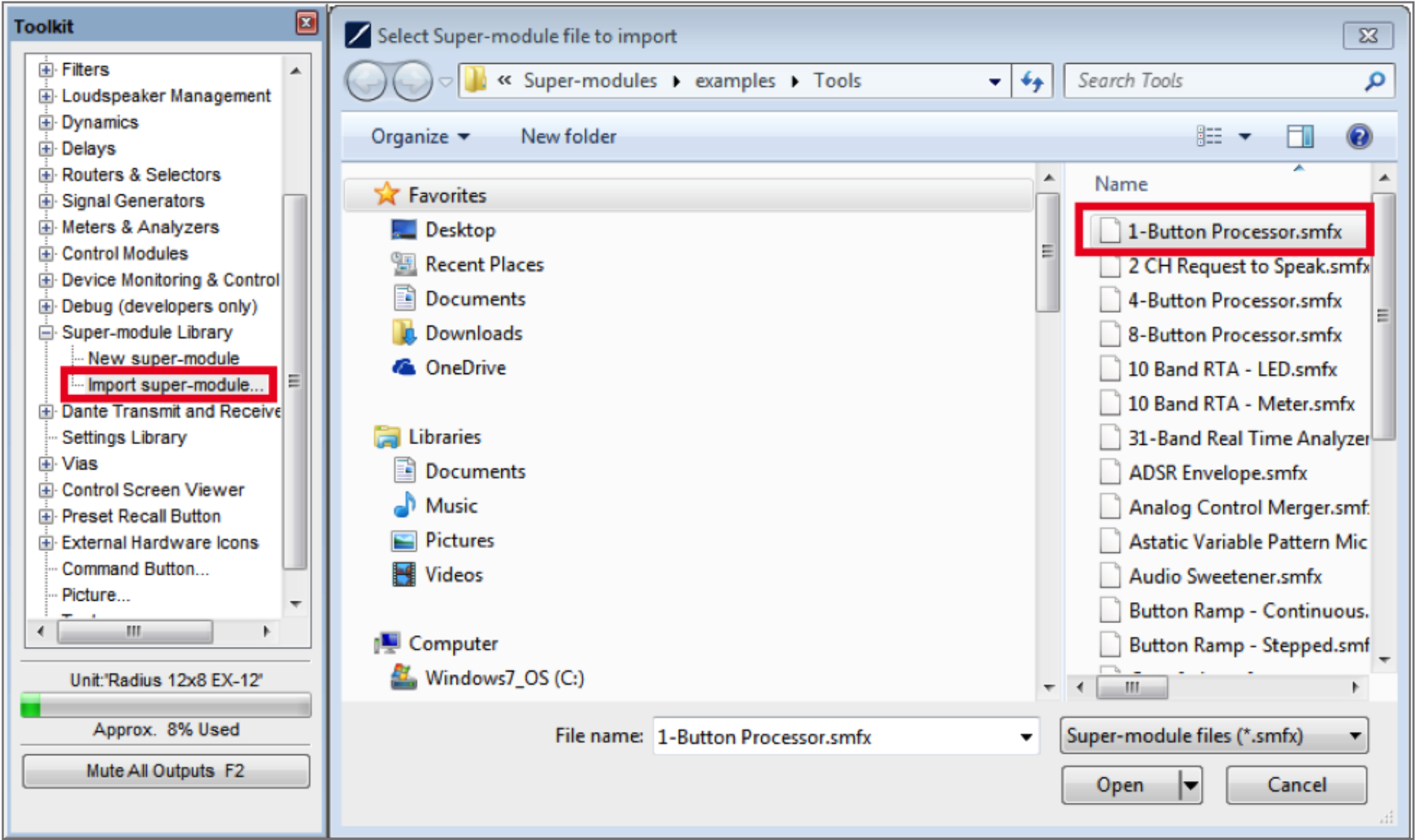
Dante-enabled Audio-Technica and Shure Mics:
The process for both Audio-Technica and Shure microphones is the same unless otherwise noted.
1 Drag in a 1-Button Momentary module from the toolkit, and wire to the
“Button 1” input on the super-module.

2. Double-click the 1-Button Momentary module to bring up its GUI. Right click
directly on the “On” button, then click “Set Up to Remote Control” and select the relevant Audio-Technica or Shure device from the “Remote Control Device” dropdown menu.
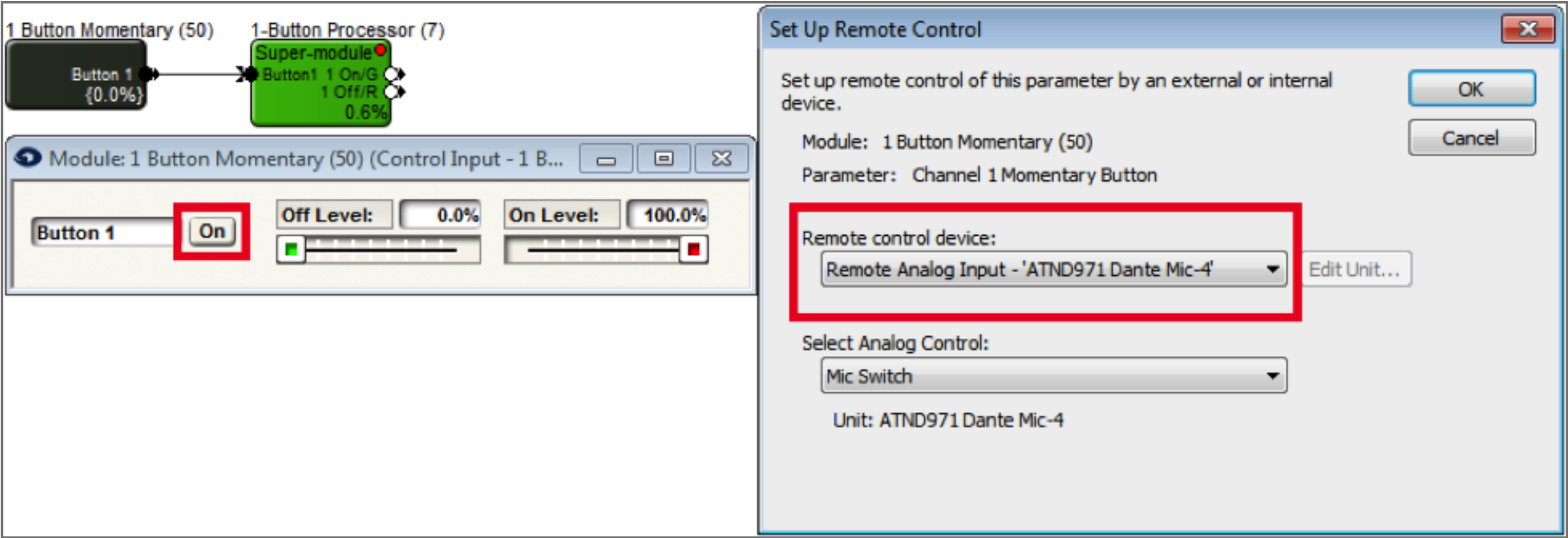
3. From Control Modules->Control Outputs, drag in a “Remote Logic Output” module. In the Remote Logic Output Properties window, choose the Audio-Technica or Shure device, as well as the Green LED option.
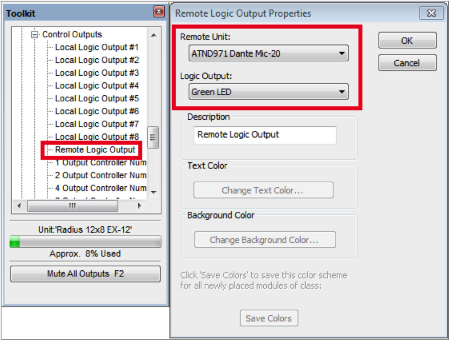
4. Wire the super-module output labeled “1 On/G” to the input of the Remote Logic Output from step

5. From Control Modules->Control Outputs, drag in a second “Remote Logic Output” module. In the Remote Logic Output Properties window, choose the Audio-Technica or Shure device, and the Red LED option.
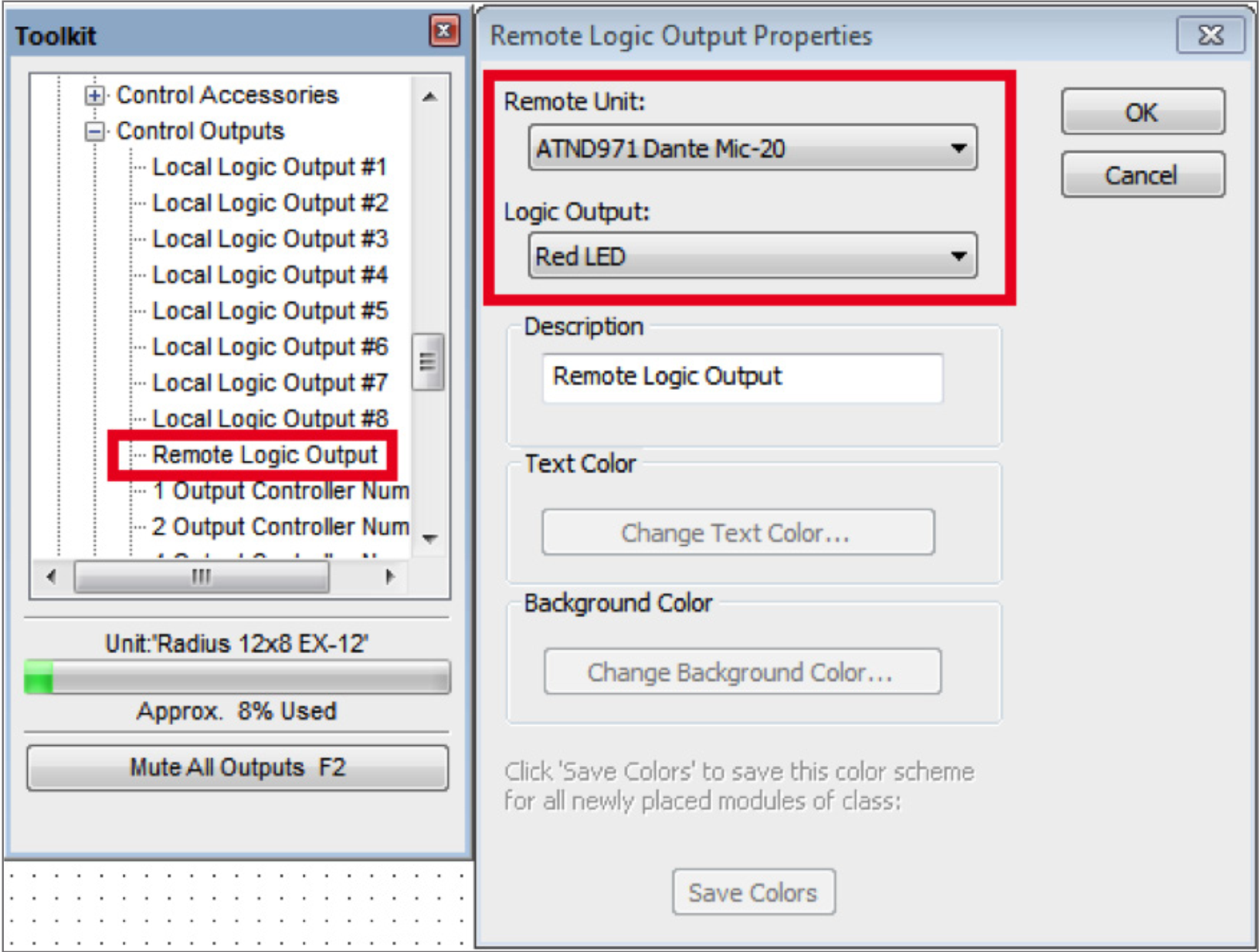
6. Wire the super-module output labeled “1 Off/R” to the input of the second Remote Logic Output from step 7. Assuming you’ve set up the receive flow to bring the Dante mic’s audio into the DSP, your site file should now look something like this
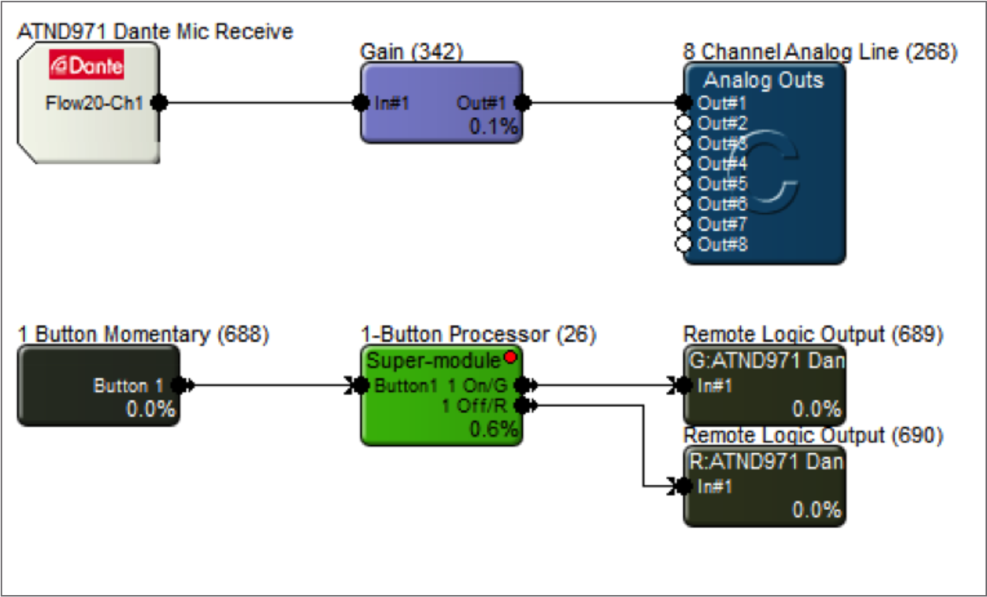
7. Navigate to the Mute button for the mic channel you’re planning to control. Right-click it, select “Set Up Remote Control” and choose “Control Signal Assignment”. Click the “Select” button, and click the plus sign next to “1-Button Processor”. Highlight “1 Off/R”, then click OK.
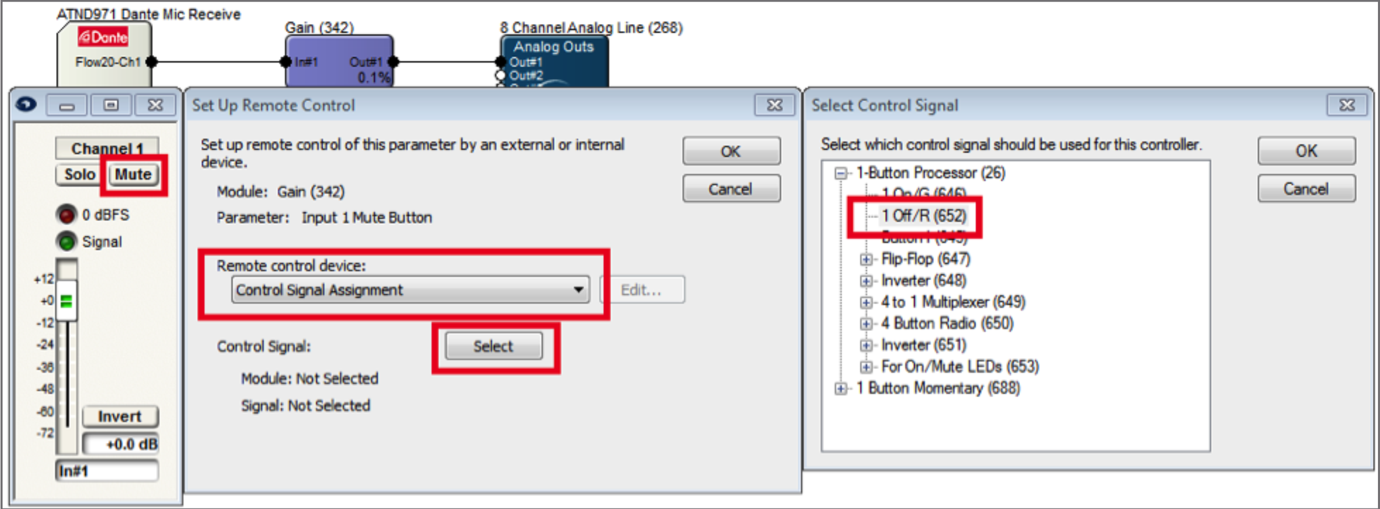
8. Open the super-module user interface and select the preferred switch mode. Go online and test the switch while watching the super-module GUI. The Input LED will light when the switch is closed, and the On/Mute LEDs will respond accordingly.
For momentary analog switches (connected to an External Control Input on the DSP):
9. Drag in a 1-Button Momentary module from the toolkit, and wire to the “Button 1” input on the super-module.
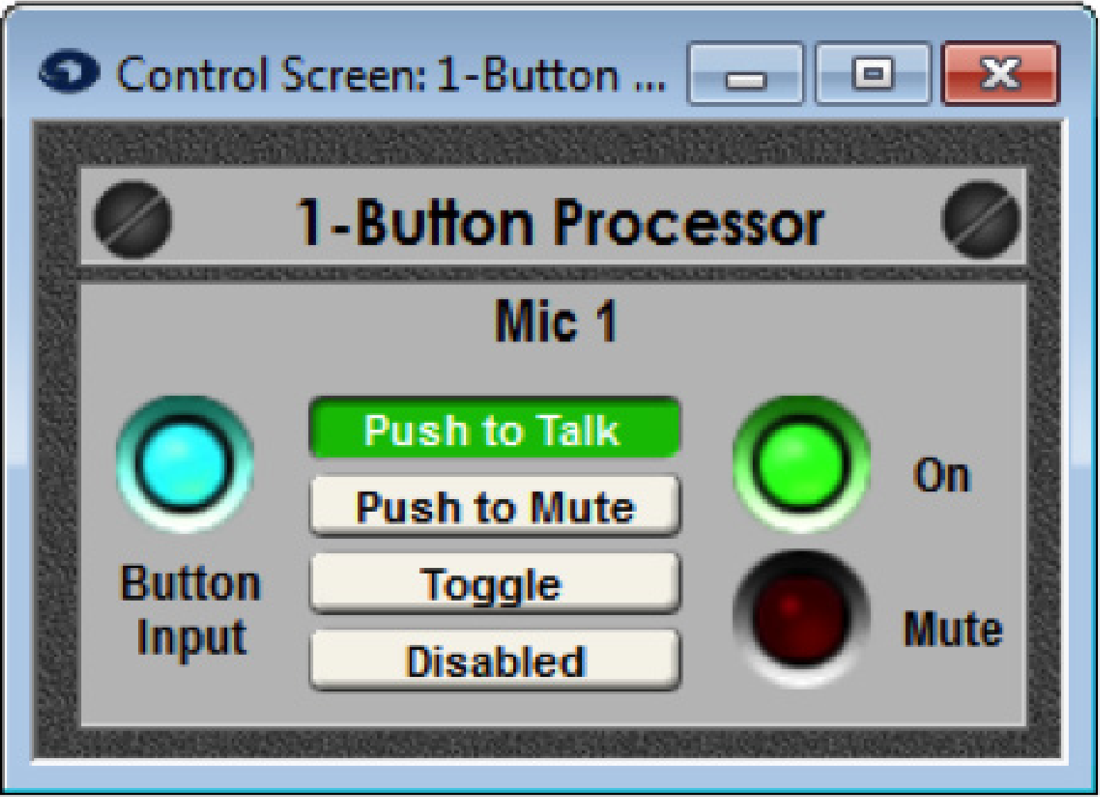
10. Double-click the 1-Button Momentary module to bring up its GUI. Right-click directly on the “On” button, then click “Set Up to Remote Control”. Choose “Local Analog Input”, then select the physical External Control Input number the analog switch is wired into.
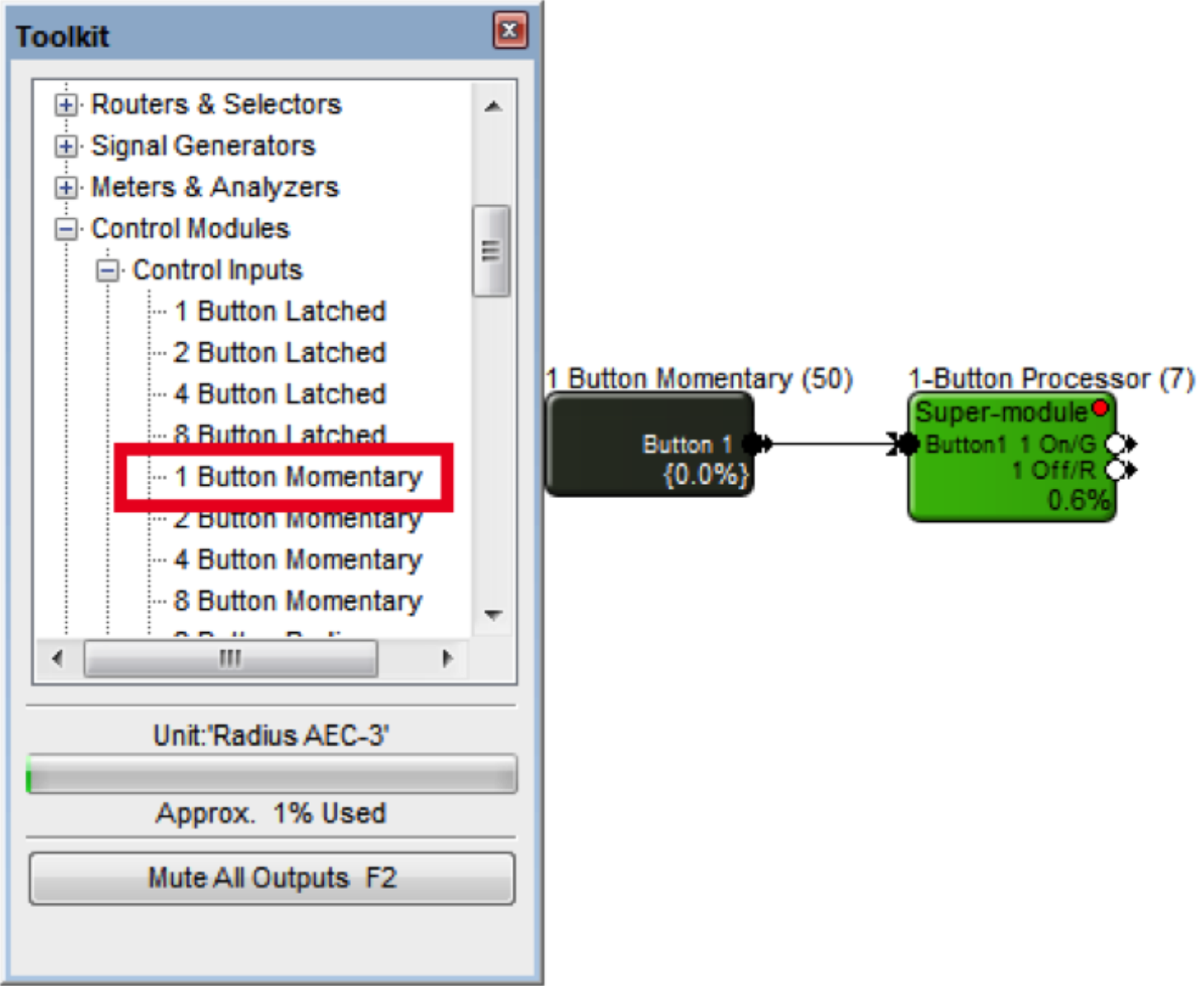
11. Go to the Mute button that is to be controlled by the switch. Right-click it, select “Set Up Remote Control” and choose “Control Signal Assignment”. Click the “Select” button, and click the plus sign next to “4-button Processor”. Highlight “1 Off/R”, then click OK.
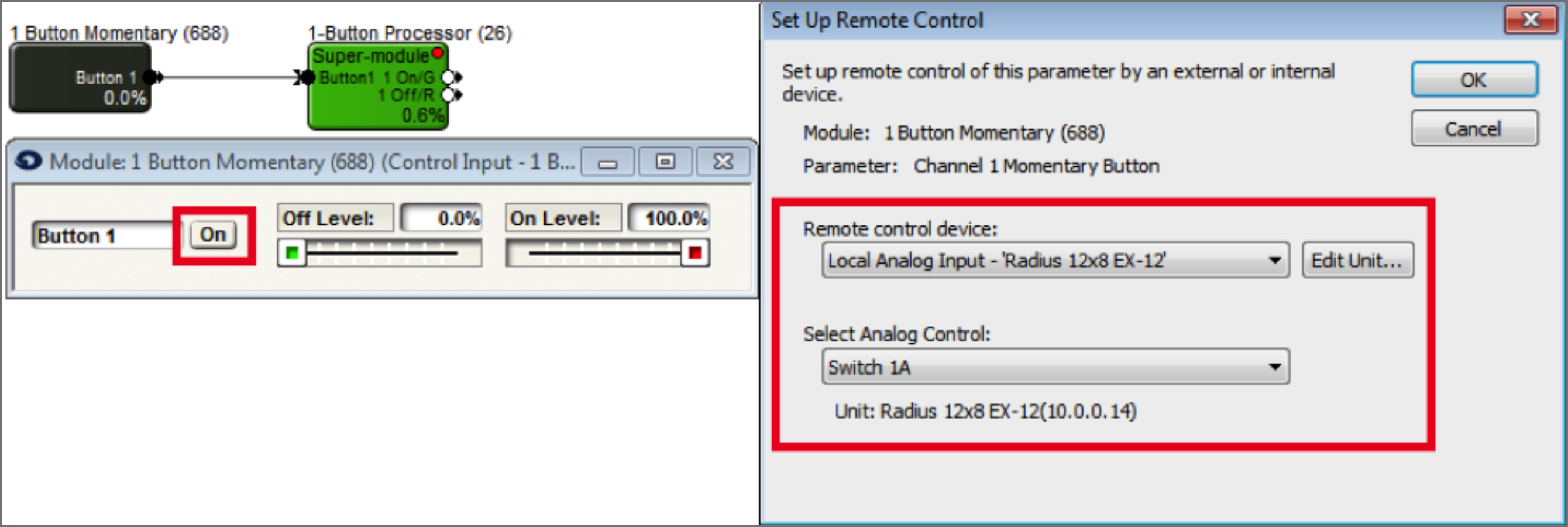
12. Open the super-module user interface and select the preferred switch mode. Go online and test the switch while watching the super-module GUI. The Input LED will light when the switch is closed, and the On/Mute LEDs will respond accordingly.
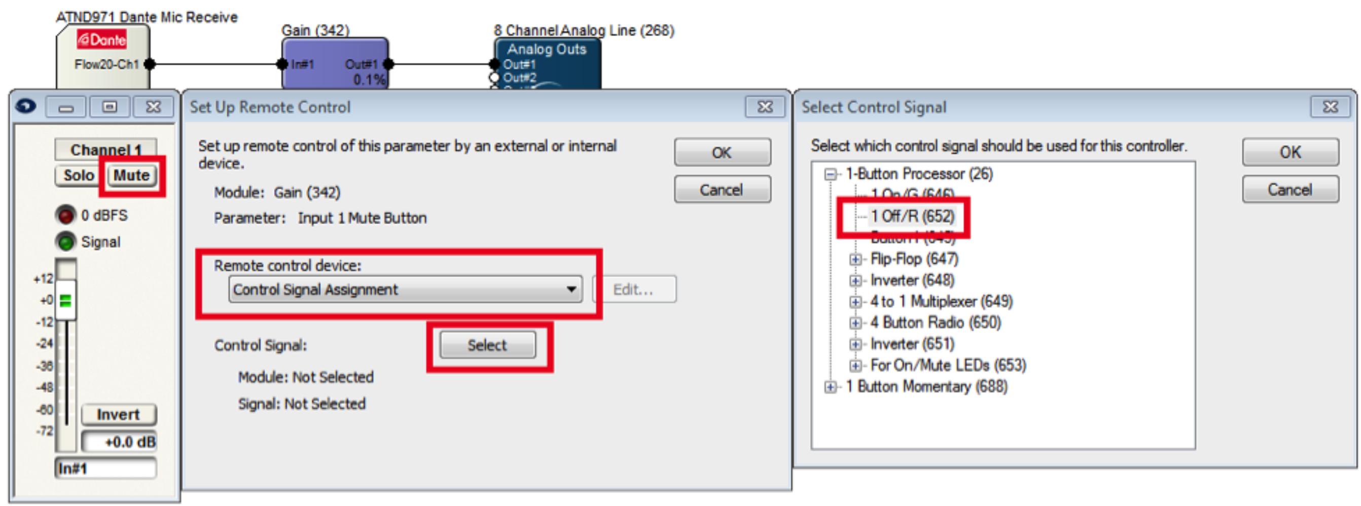
13. Repeat the process for more momentary switches.
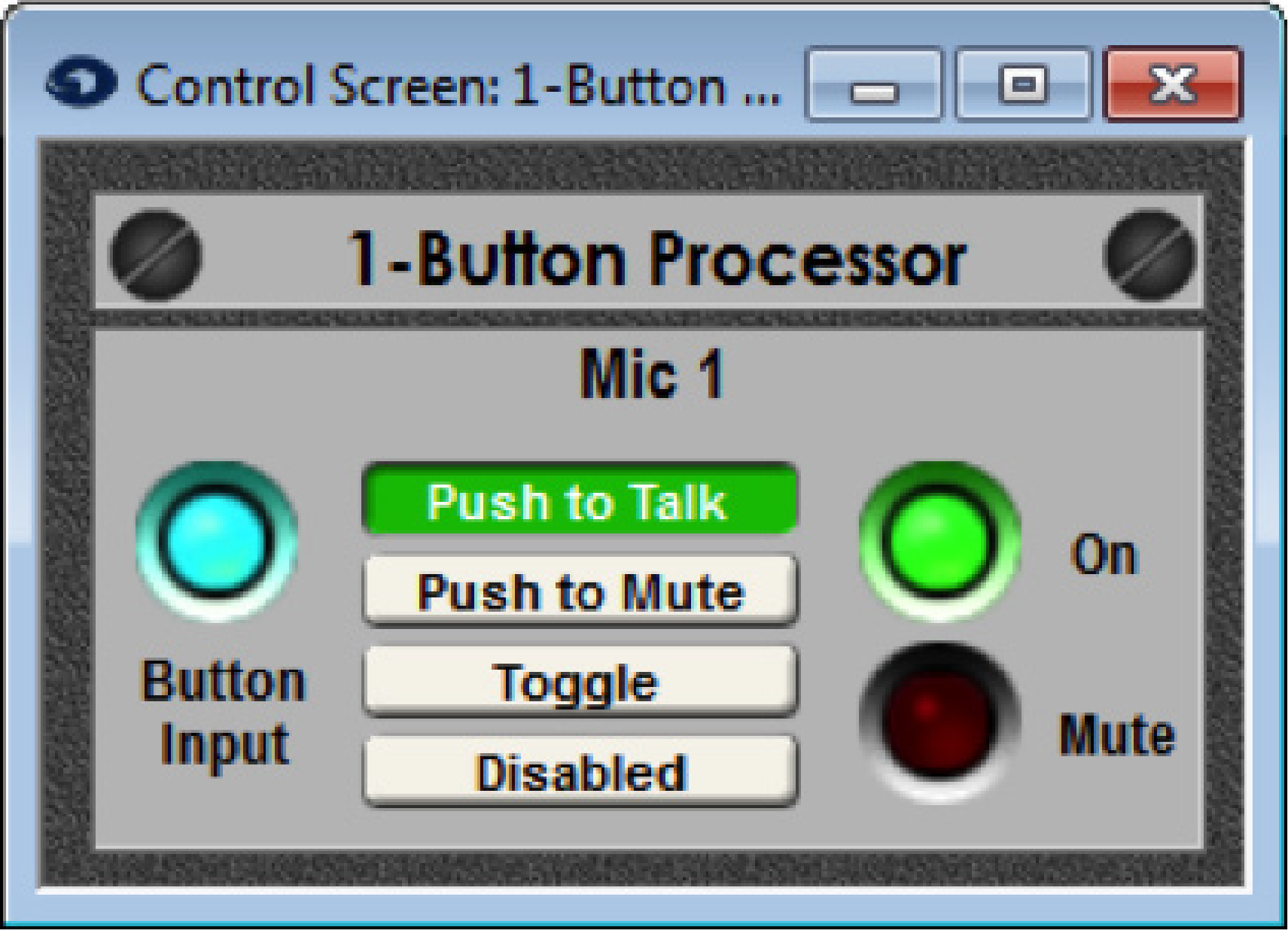
1) Open Composer to a blank site file or a site file in progress. Connecting to Dante capable Stewart Audio hardware requires a DSP such as the Edge, Radius NX, or Prism.
2) Locate a DSP by clicking the brown box in the lower left hand corner of the DSP icon.
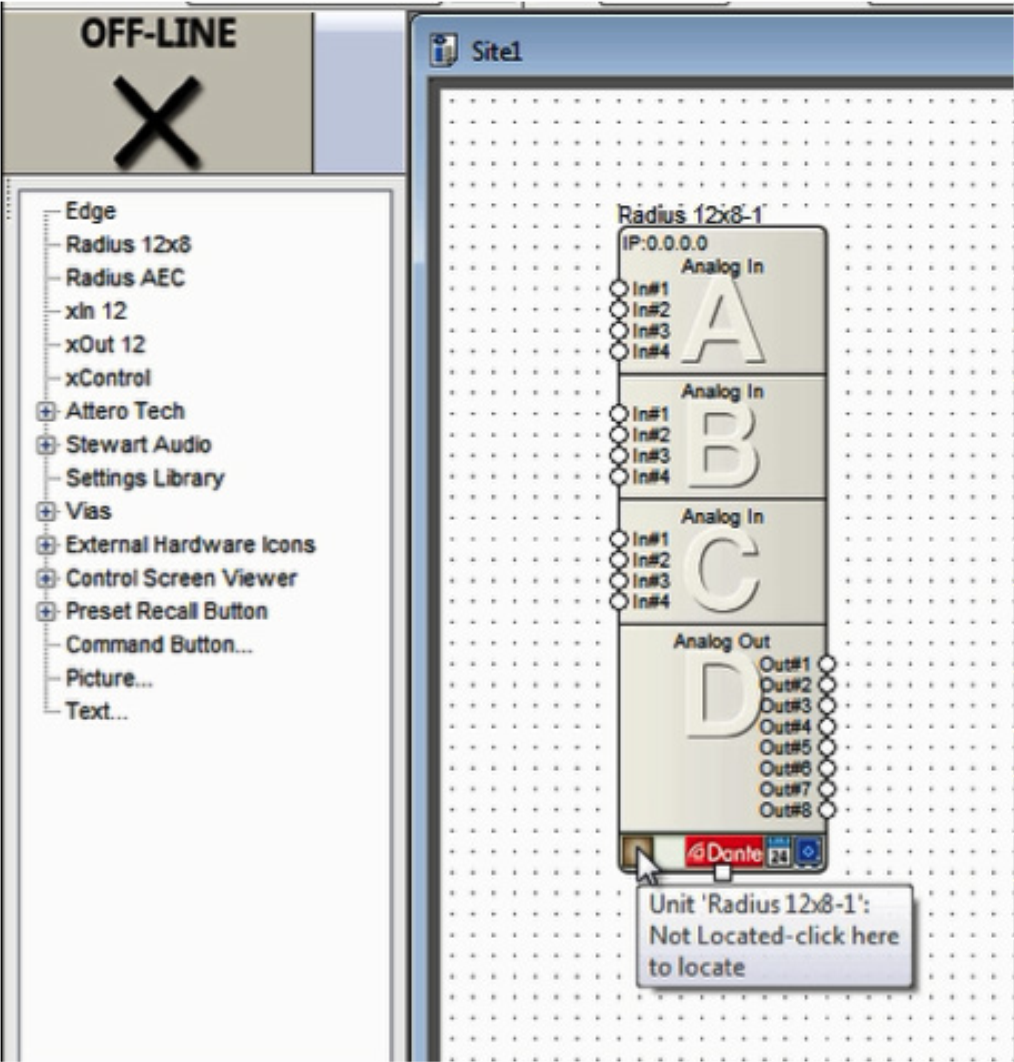
3) Select the DSP in the list of “Available Units on Network” by double clicking it. A green check indicates the DSP has been located and can now be used to connect to a Stewart Audio Dante endpoint.
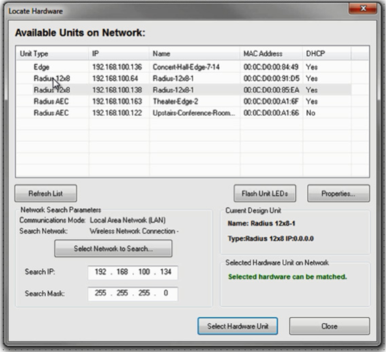
4) To receive Dante audio in a supported Stewart Audio end point (shown in yellow), drag the supported unit into the design and then click the brown box in the lower left hand corner to locate it.
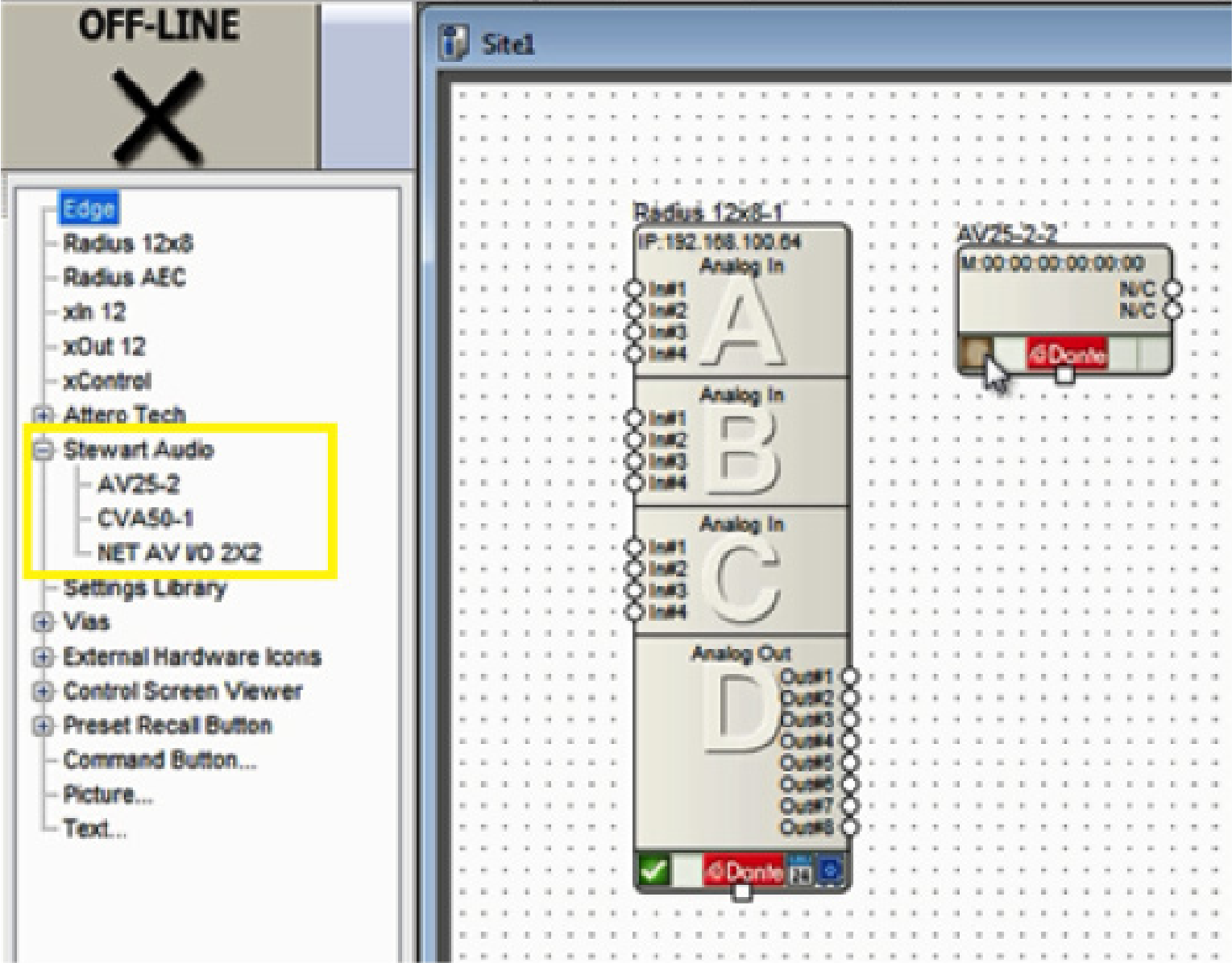
5) Composer will search the currently located DSP’s Dante network for the Stewart Audio device. Double click on its Name field to select it. A green check will indicate if the unit is connected successfully.
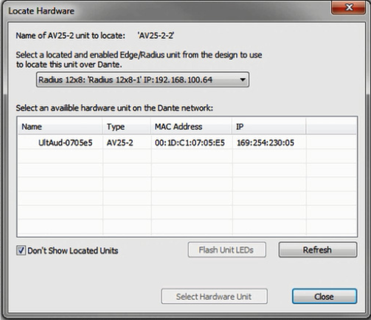
6) Enter the selected DSP’s design and be sure a Dante transmit flow already exists or create a new one to send audio to the Stewart Audio device. If a transmit flow already exists, skip to step 10.
7) To create a new transmit flow, from the Toolkit under Dante Transmit and Receive Flows, drag out New Transmit and Receive flow.
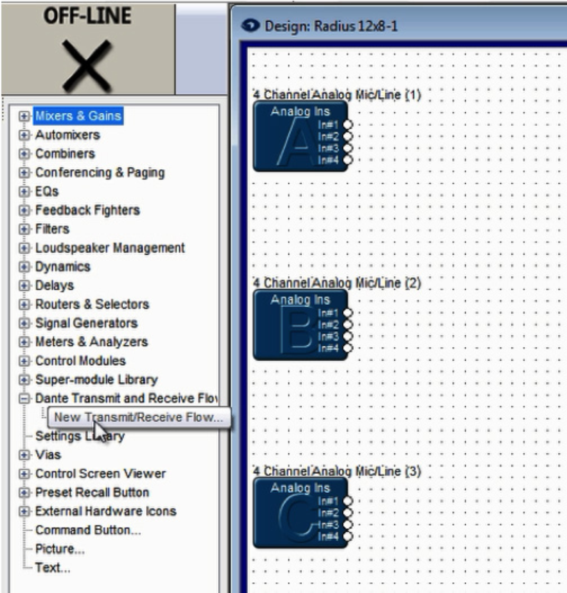
8) Name it, set its channel count to 2, set it to transmit, label the channels if desired, and click OK.
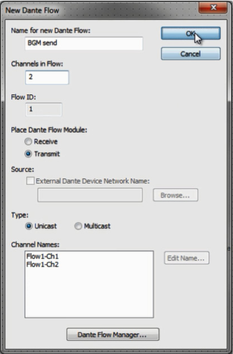
9) Wire the Dante transmit flow into the signal path as desired, then close the DSPs design screen to return to the site view.
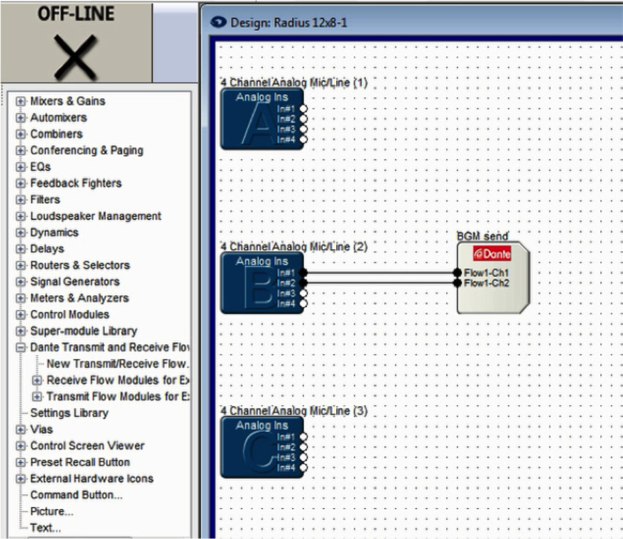
10) Double click on the Stewart Audio device to access its properties window. Under the Dante Audio Reception window, double click on channel 1 or 2.
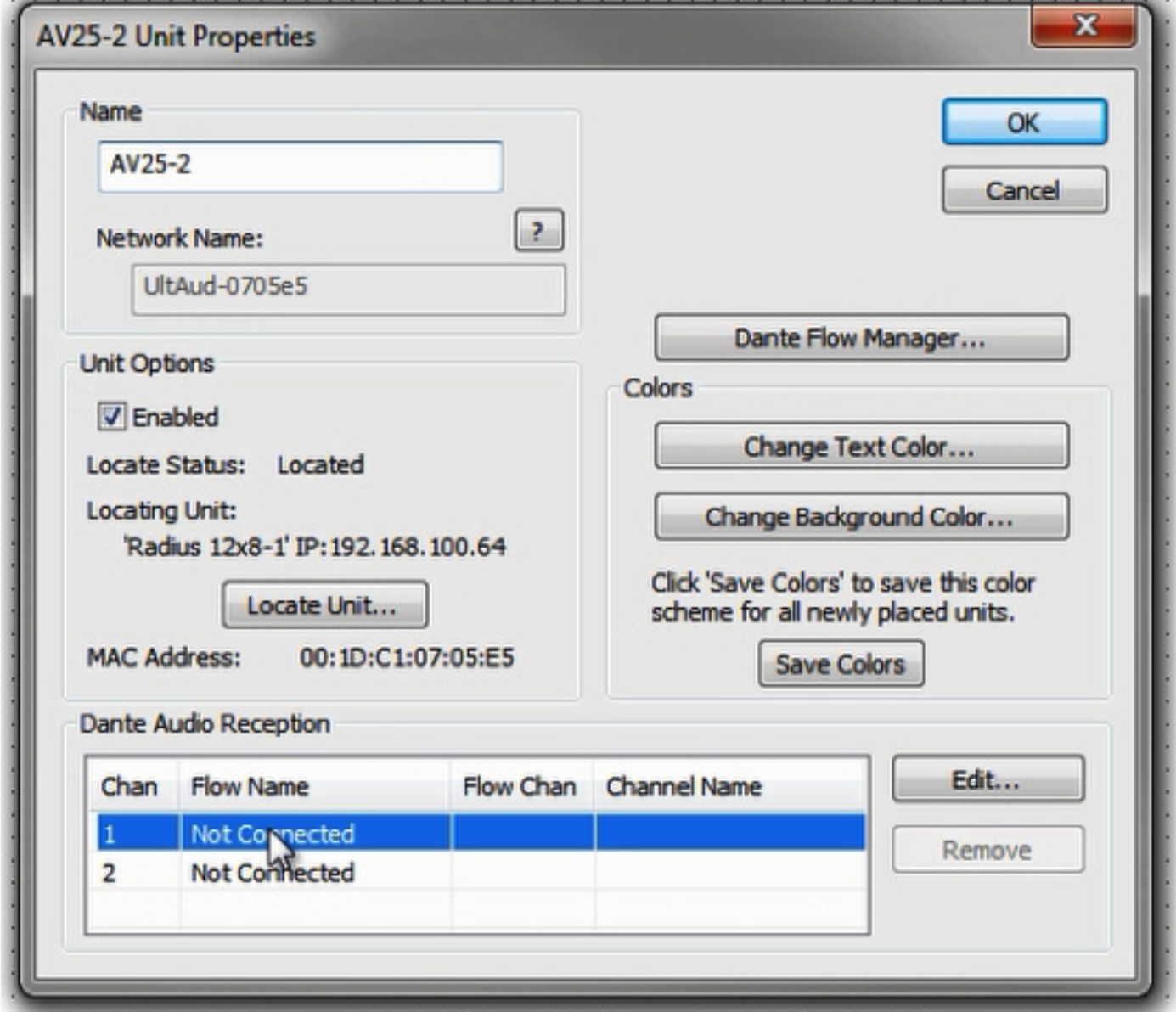
11) Select the appropriate Dante flow and the starting channel. Click OK.
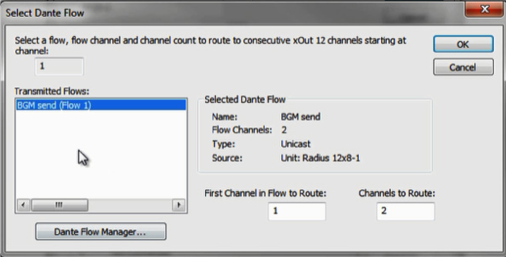
12) Dante Audio Reception should now indicate subscriptions to the transmit flows channels (shown in red). Click OK to close the Stewart Audio unit properties screen.
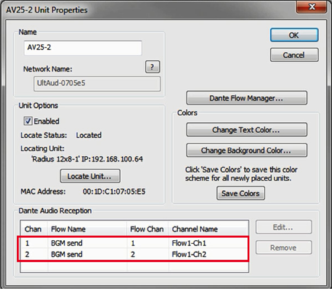
13) Push the site file to Composer. When completed, Dante audio should be passing from the DSP to the Stewart Audio device.
Note: The Stewart Audio Net AV I/O 2×2 has a pair of remote line level inputs. These inputs can be received in a DSP using the following steps.
14) Follow Steps 1 – 5 of this document, then skip to and complete steps 15-18.
15) Enter the design screen of a DSP by double clicking its icon in the Composer site view.
16) From the Toolkit under Dante Transmit and Receive Flows, expand the Receive Flow Modules for Existing Flows. Then drag the auto-generated Receive Flow from the Stewart Audio Net AV I/O 2×2 unit into the design. The default name of the Flow will include the Stewart Audio Dante network name, for example “Untitled Net AV I/O 2×2 Flow #1”. This is where the incoming audio from the Attero Tech will be received.
17) Wire the receive flow into the signal path as desired.

18) Push the site file to Composer. When completed, Dante audio should be passing from the Stewart Audio device to the DSP.
1) Open Composer and create a blank Site File or open an existing one.
Note: Connecting to Dante capable Attero Tech endpoint requires a DSP such as the Edge, Radius NX, or Prism.
2) If starting with a blank Site File, first drag a DSP into the Configuration from the Toolkit.
3) Locate a DSP by clicking the brown box in the lower left hand corner of its unit icon
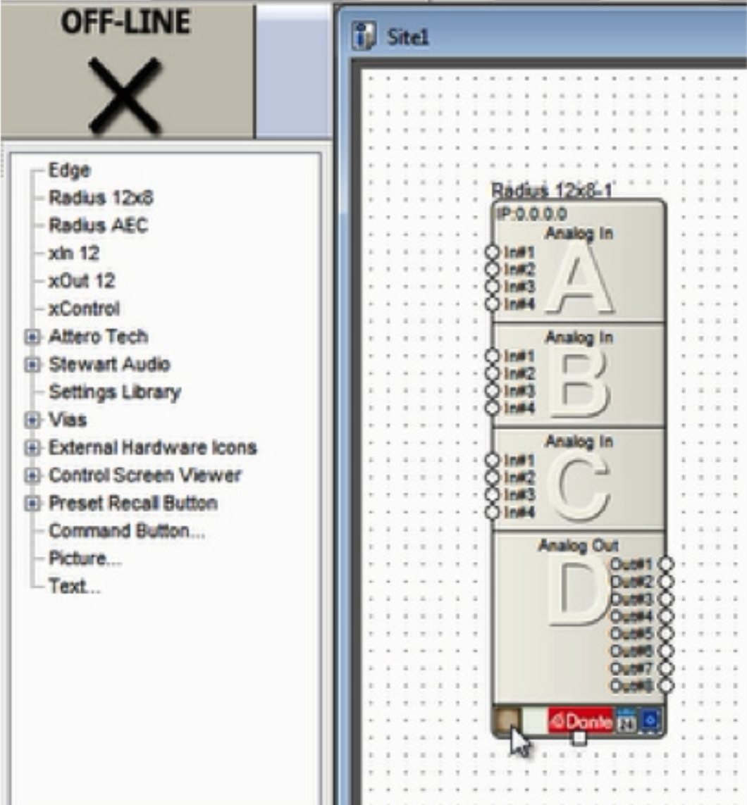
4) Select the DSP in the list of “Available Units on Network” by double-clicking it.
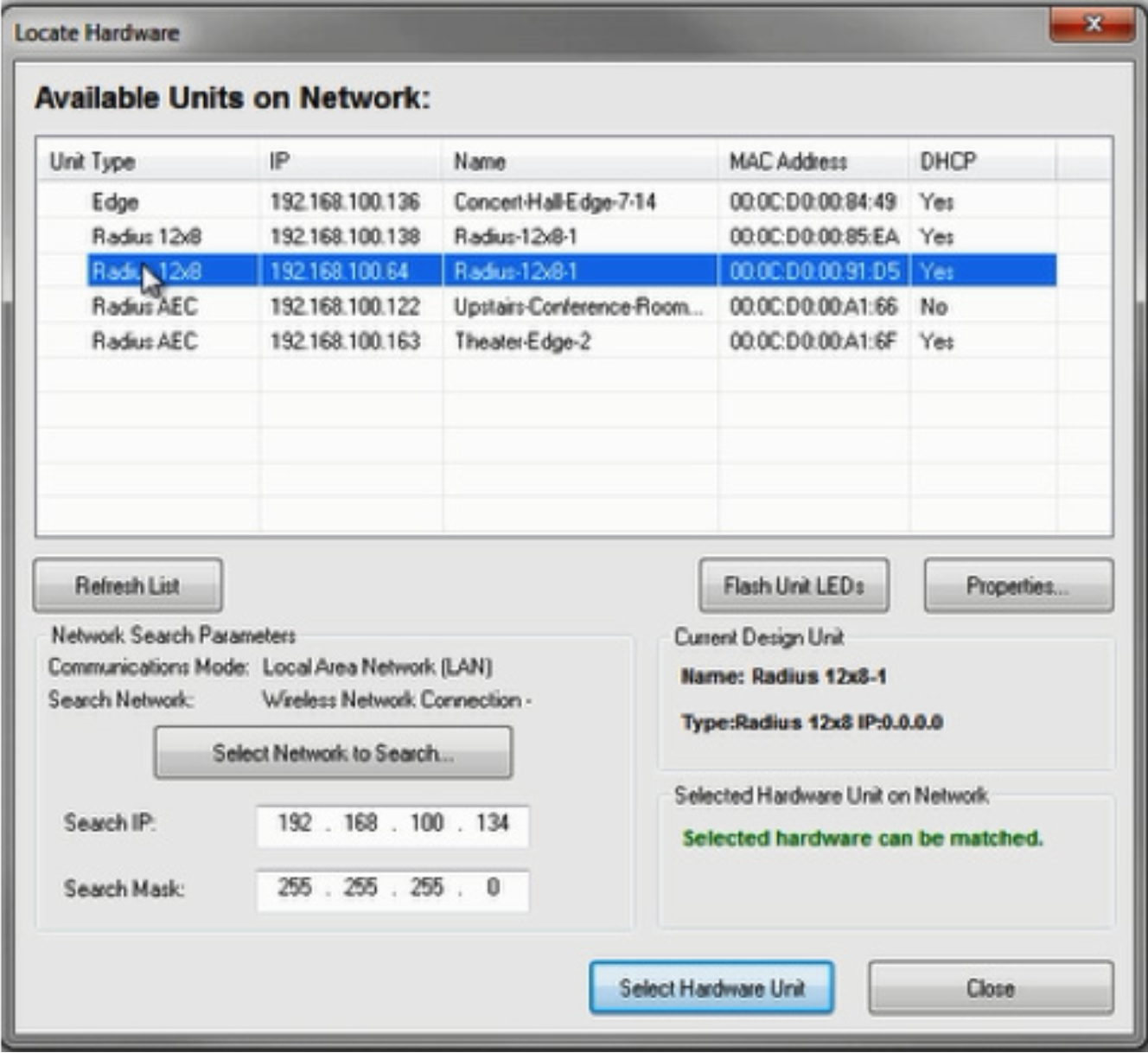
5) A green check indicates the DSP has been located and can now be used to connect to a Dante capable Attero Tech endpoint.
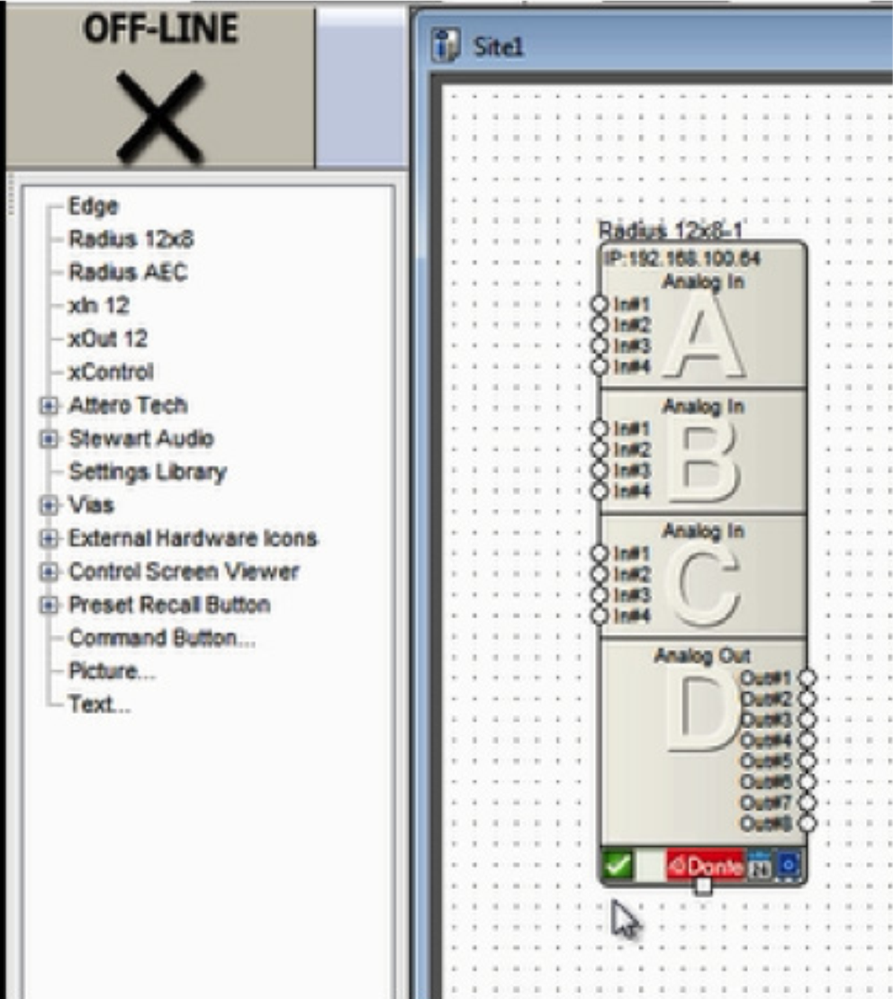
6) Drag a supported Attero Tech device into the Configuration from the Toolkit.
att 1
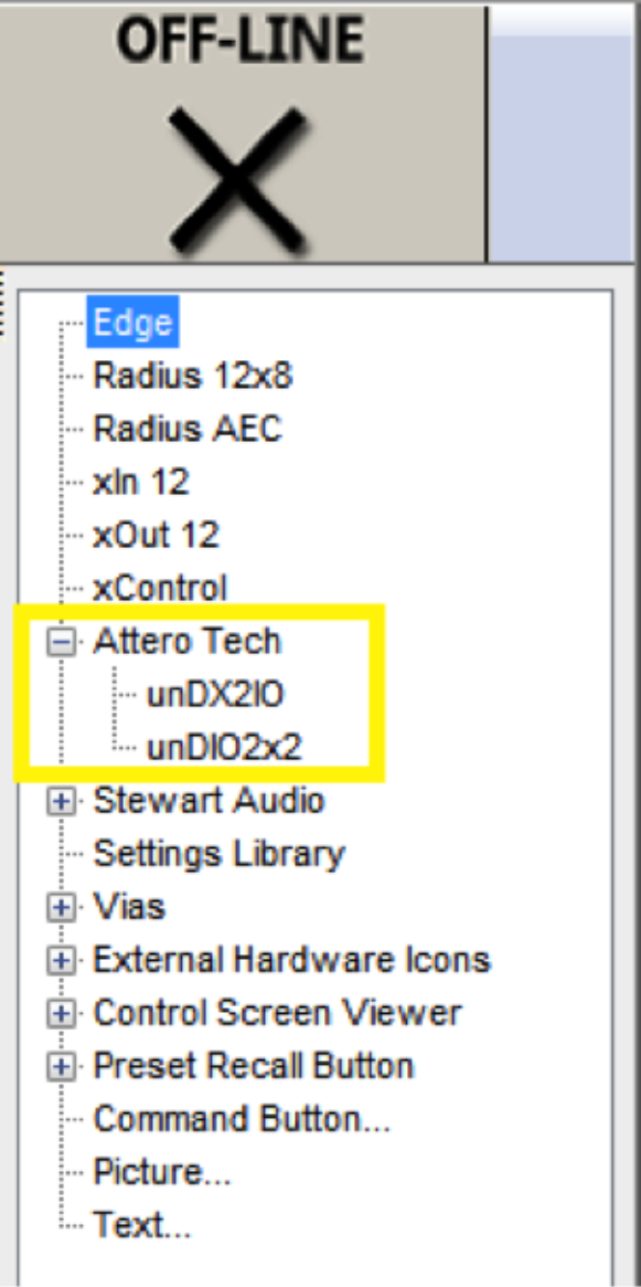
6) Drag a supported Attero Tech device into the Configuration from the Toolkit.
7) Click the brown box in the lower left hand corner of its unit icon to locate it.
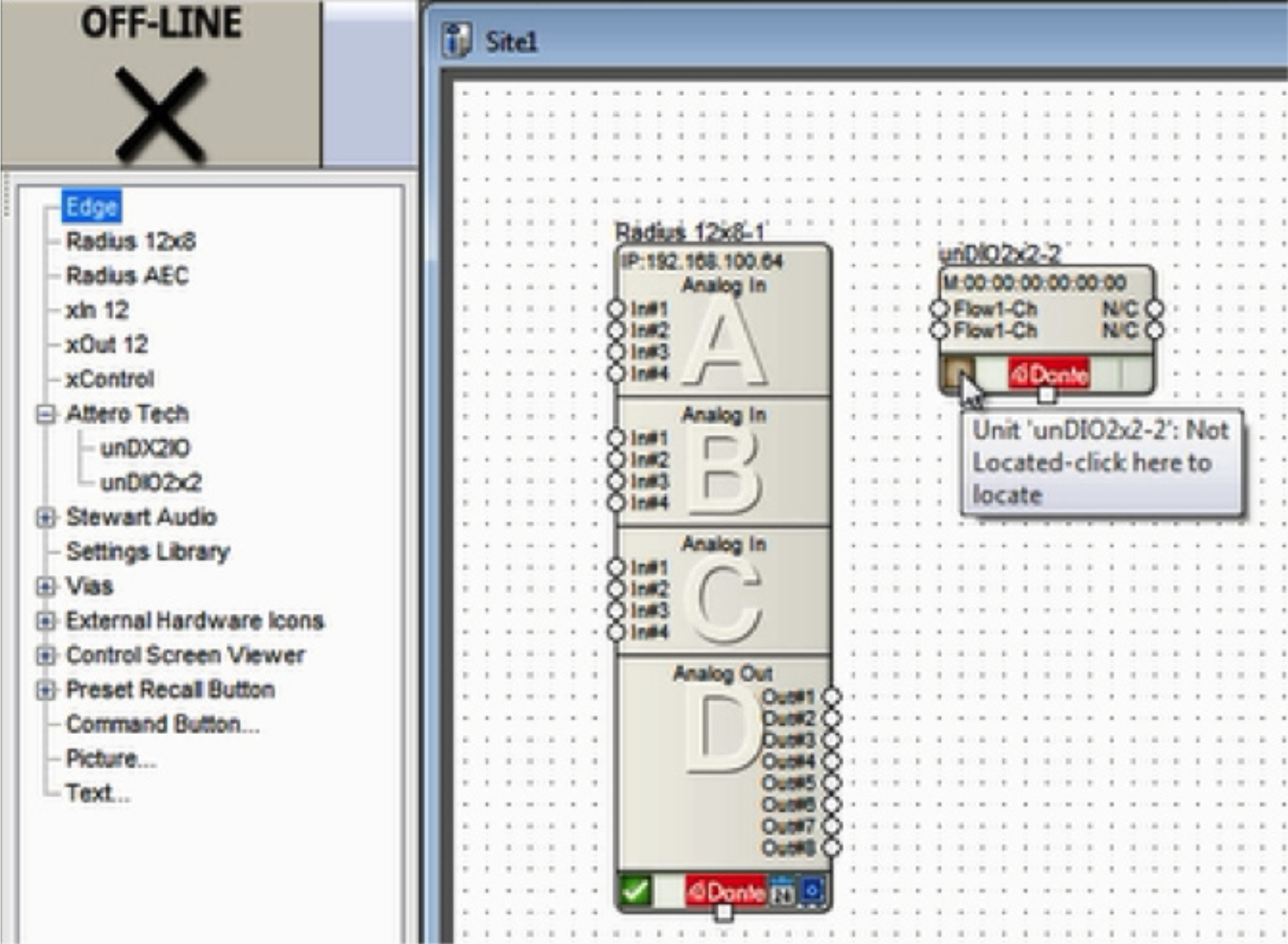
8) Composer will search the currently located DSP’s Dante network for the Attero Tech model in the configuration. Double-click on its Name field to select it.
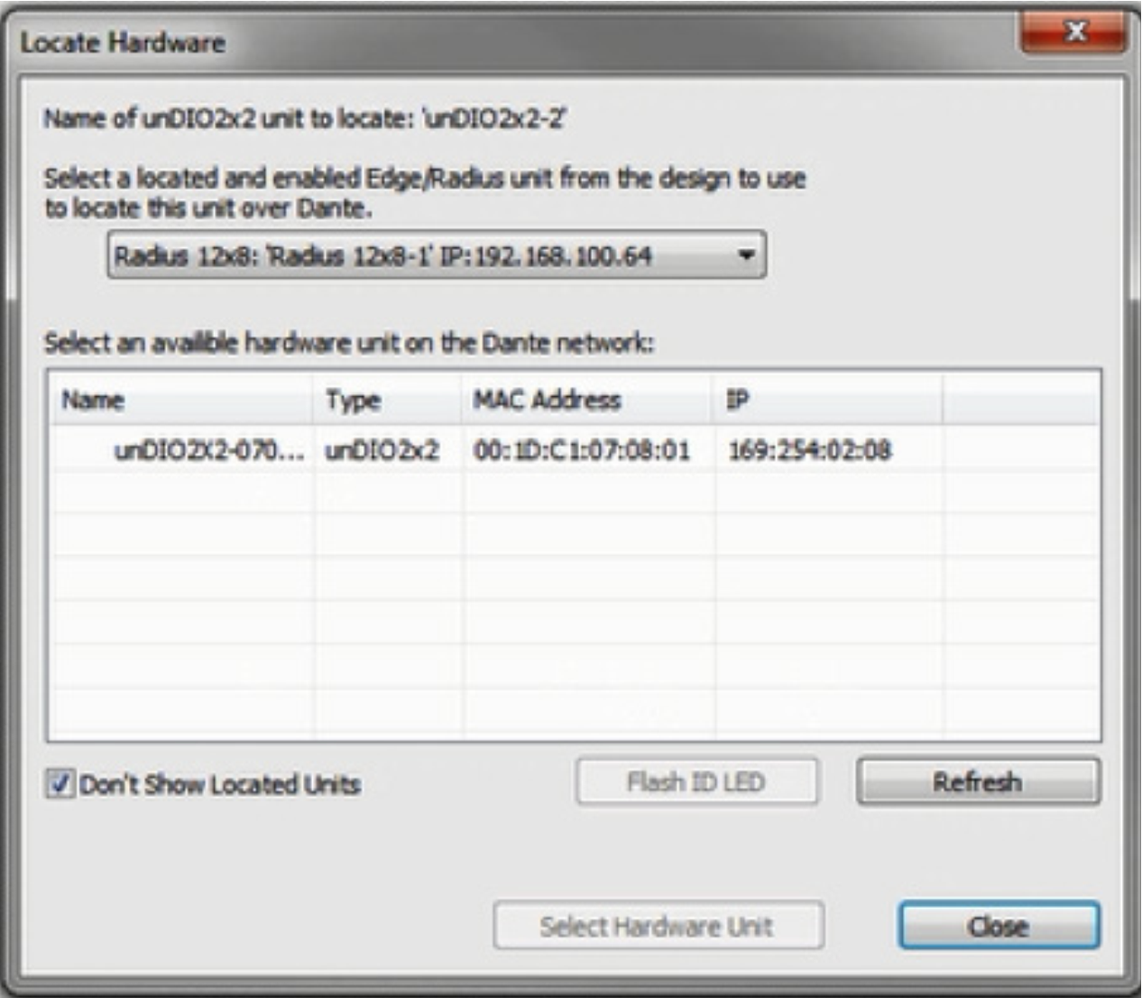
9) A green check will indicate if the unit is connected successfully.
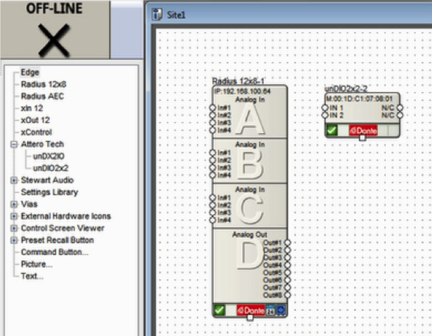
10 ) To receive audio from the Attero Tech endpoint, enter the located DSP’s design by double clicking its unit icon.
11) From the Toolkit under Dante Transmit and Receive Flows, expand the Receive Flow Modules for Existing Flows. Then drag the auto-generated Receive Flow from the Attero Tech unit into the design. The default name of the Flow will include the Attero Tech Dante network name, for example “Untitled unDIO2x2 Flow #1”. This is where the incoming audio from the Attero Tech will be received.
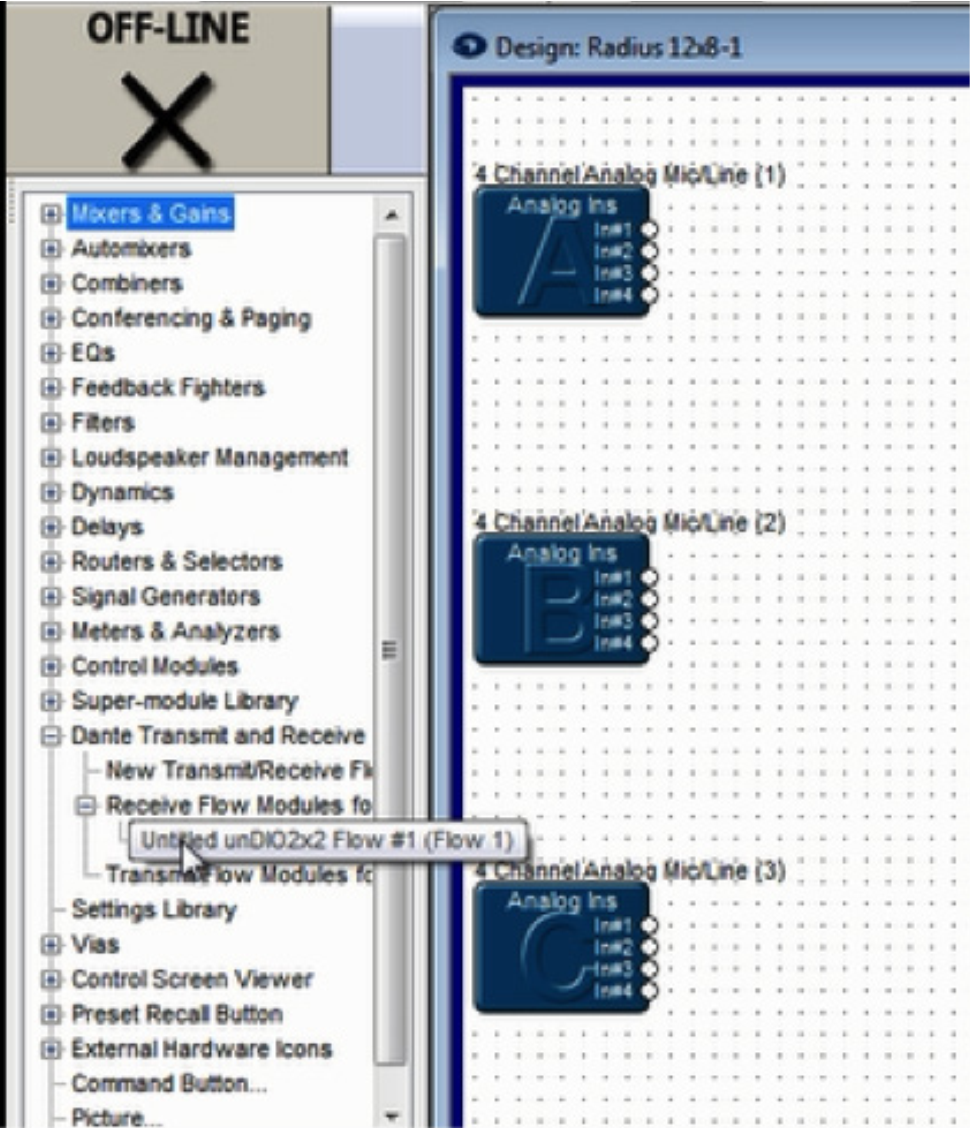
12) Wire the Receive Flow into the audio signal path as desired.
13) To send audio to the Attero Tech endpoint’s outputs be sure a Dante Transmit Flow already exists in the design, or create a new one.
Note: If a Transmit Flow already exists in the design, skip to step 15.
14) To create a new Transmit Flow, from the Toolkit under Dante Transmit and Receive Flows, drag a New Transmit and Receive Flow into the design. In the resulting dialog, name it, set its Channels in Flow to 2, set it to Transmit, label the Channel Names if desired, and click OK.
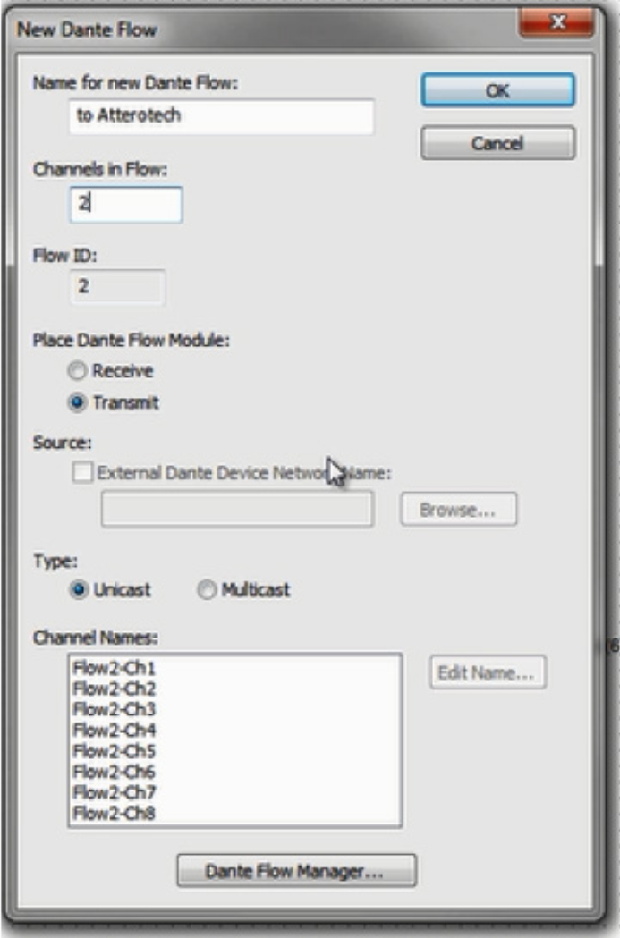
15) Wire the Transmit Flow into the audio signal path as desired.
16) Close the DSPs Design View to return to the Site View.
17) Double-click on the Attero Tech unit to access its Unit Properties dialog.
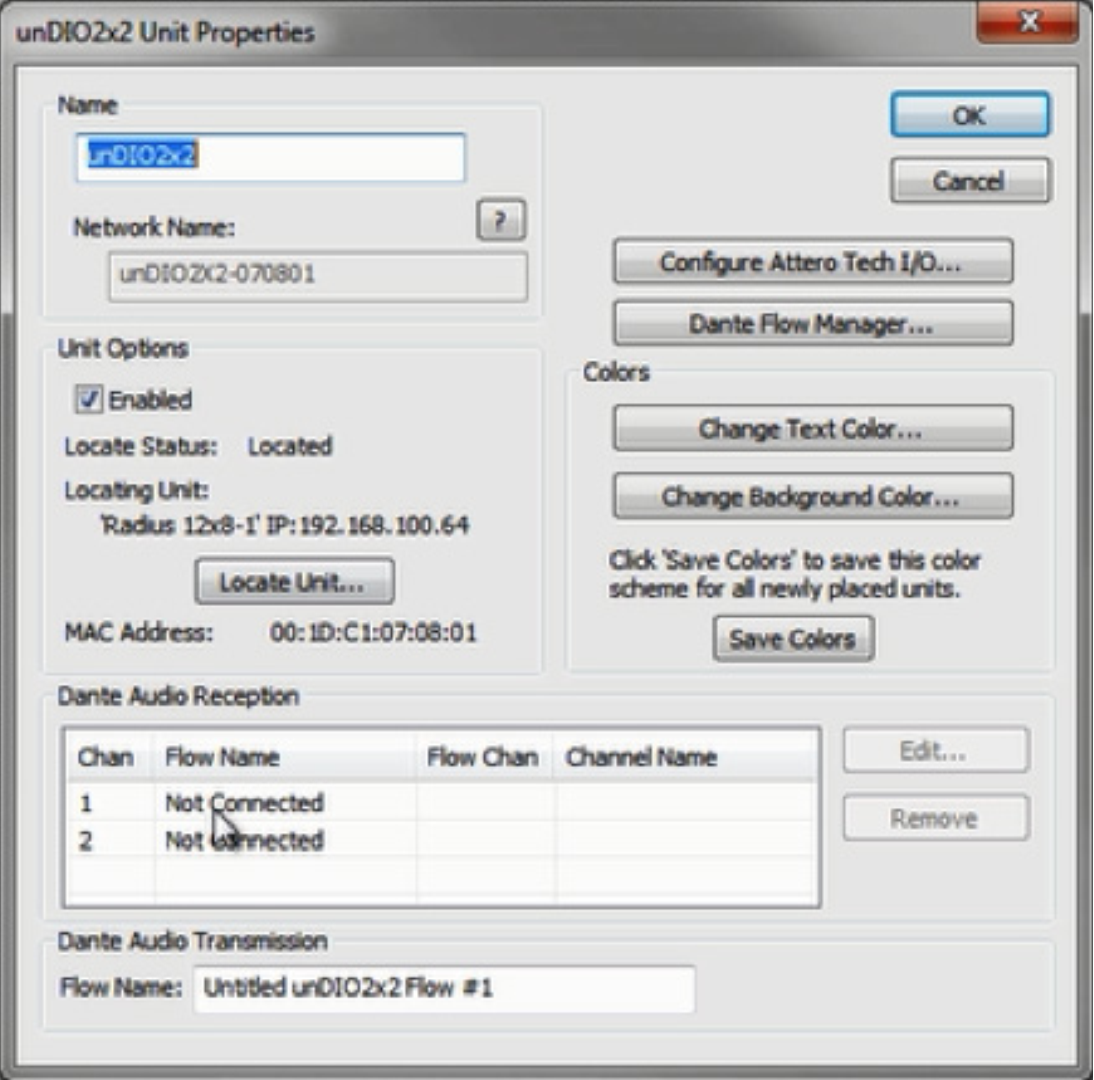
18) Under Dante Channel Reception, double-click on channel 1 or 2. Select the appropriate Dante Flow and the starting channel, typically channel 1, and click OK.
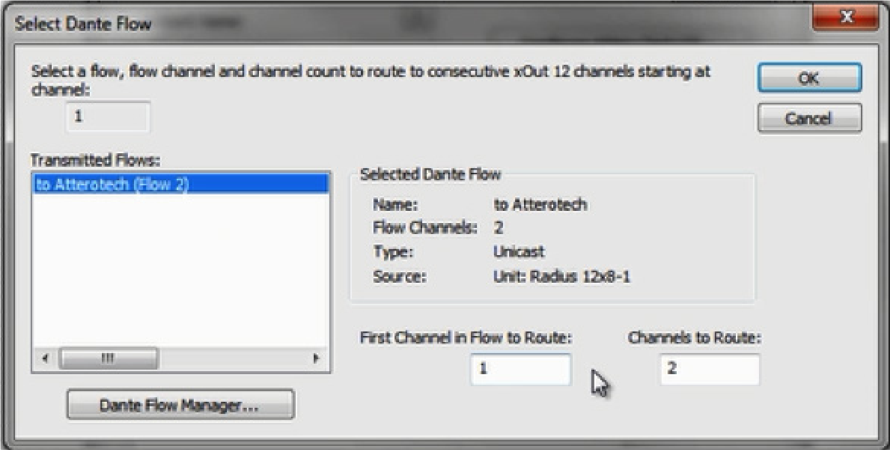
19) The Dante Audio Reception section should now indicate subscriptions to the Transmit Flow’s channels, shown in yellow below:
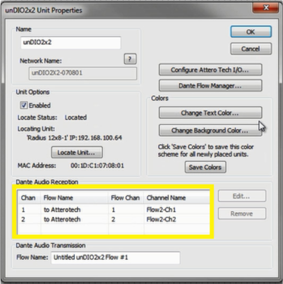
20) Next, click the Configure Attero Tech I/O button and set the inputs and outputs to the desired levels. Be sure the “Set Default Power on Settings” option is checked.
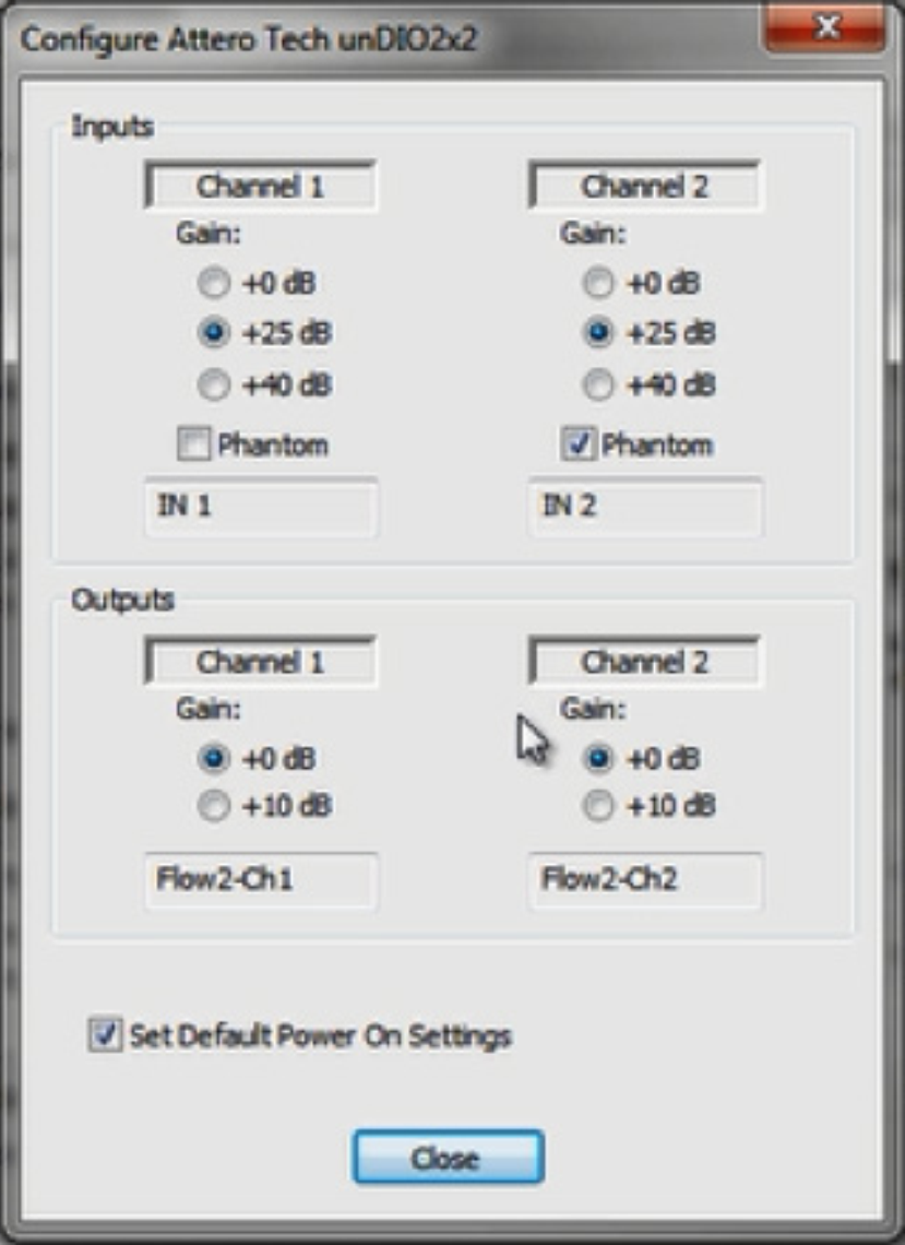
21) Click OK to close the Attero Tech properties screen.
22) Push the Site File. When completed, Dante audio should be passing bi-directionally between the DSP and the Attero Tech endpoint.
This tech tip will provide instructions for recording audio from your Dante bus in Composer to your computer via the Dante Virtual Sound Card or Dante Via with ASIO or WDM supported recording software.
Potential Applications:
- House of Worship – Recording sermons and choirs
- Theatre/Live Audio – Recording live shows and performances
- Courtrooms – Recording court proceedings
- Conference Room – Recording conference or troubleshooting AEC
What you will need:
- Symetrix Composer
- Symetrix Dante enabled DSP (Prism, Radius and/or Edge)
- Dante Controller (www.audinate.com)
- Dante Virtual Soundcard (DVS) or Dante Via (www.audinate.com)
- An ASIO or WDM capable program such as Cubase, Logic, Sound Forge, ProTools, Reaper or Audacity
Creating your Dante Bus:
1) Connect your computer to your Symetrix Dante enabled DSP via the Ethernet port.
2) Open Composer.
3) From the Toolkit add the DSP to the site view page.
4) Double click the DSP and open the design view page.
5) Create a Dante transmit flow. Toolkit>Dante Transmit and Receive Flows>New Transmit/Receive Flow…
6) Enter your Dante Flow name, select the amount of channels you need, make sure Transmit is selected and label the channels.
7) Select OK.
8) Wire your audio source into your Dante Bus.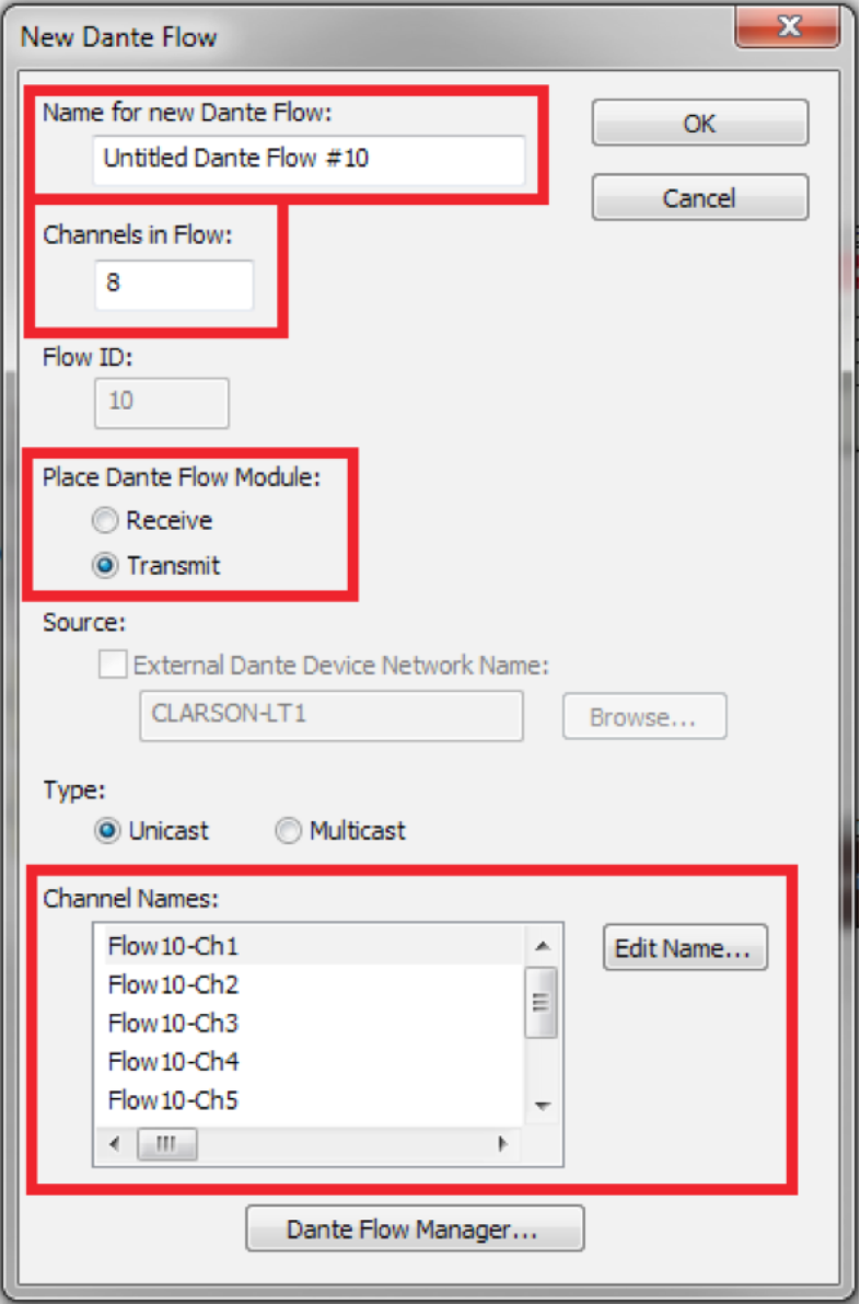
9) Go on-line with your DSP
Now that you have the site file archived in your DSP, we can connect your computer to your Dante network.
1) Connect your computer to the Dante Network.
2) Open and enable your Dante Virtual Sound Card or Dante Via.
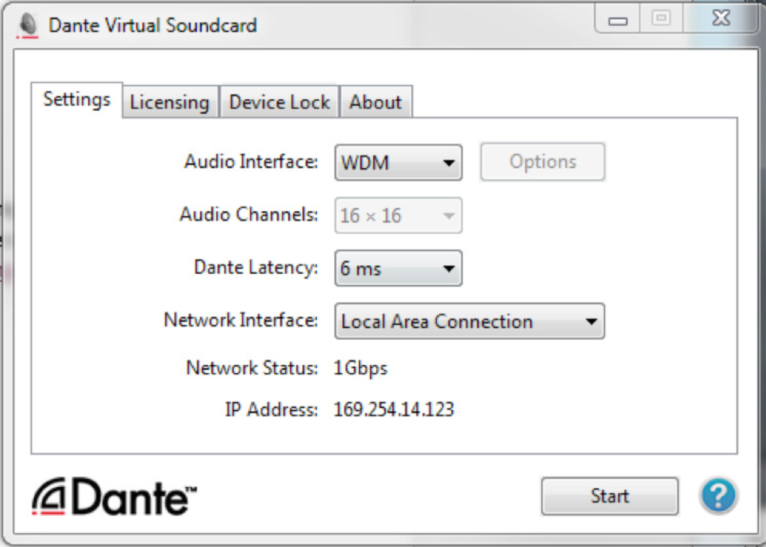
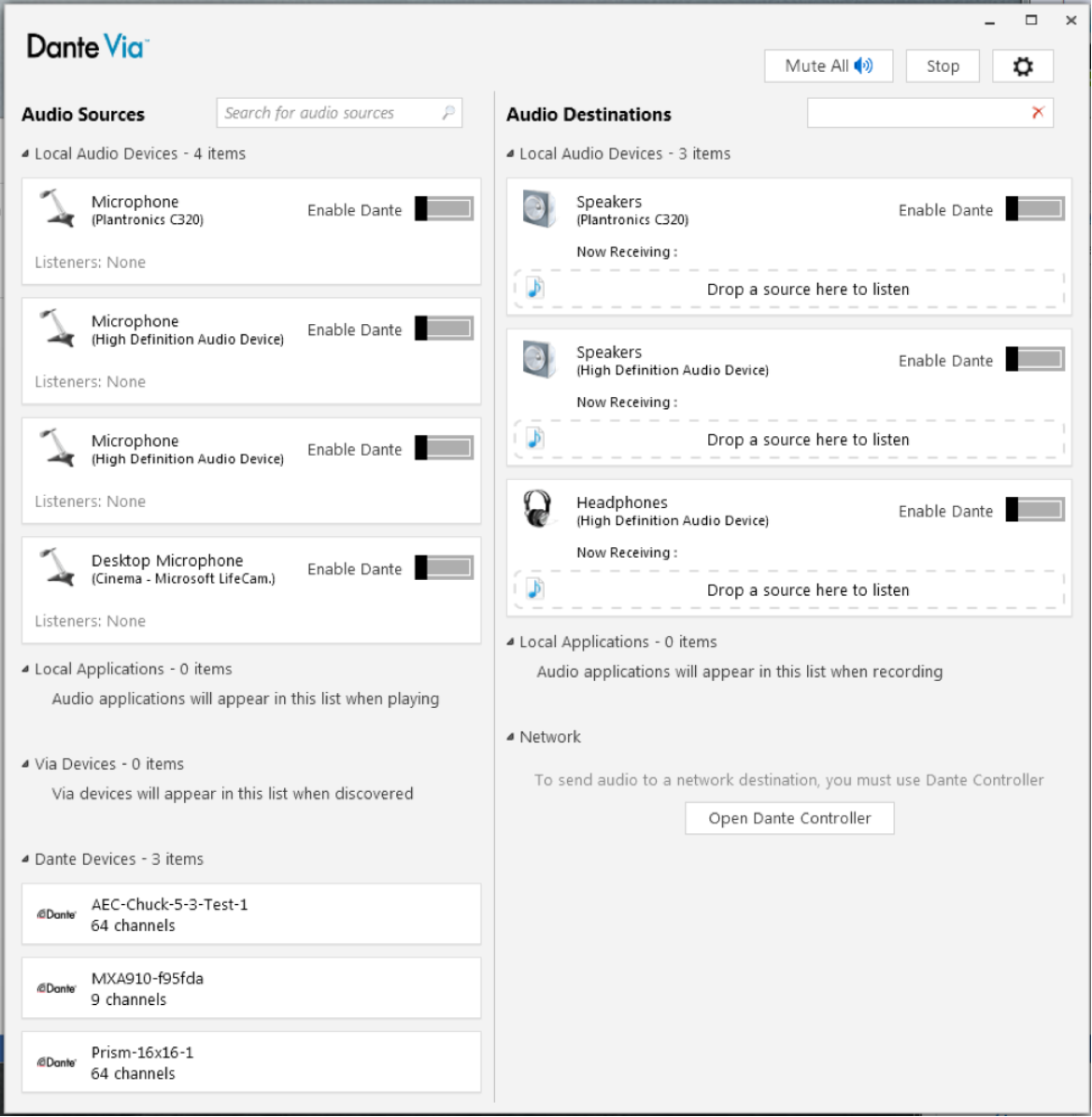
3) Open Dante Controller and create the subscriptions between the DSP and your computer.
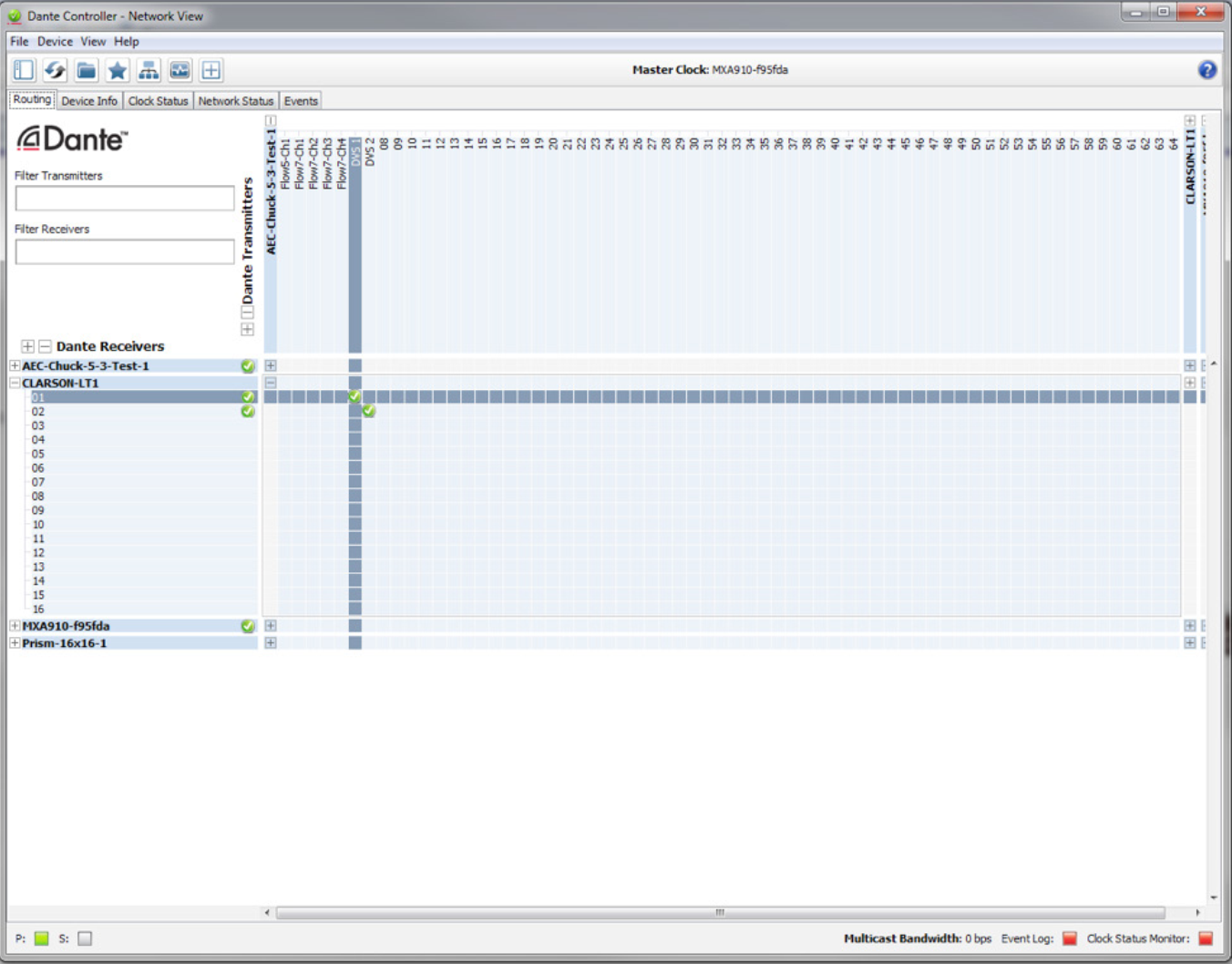
We can now open your ASIO or WDM capable program.
This example will be utilizing Reaper:
1) Open Reaper.
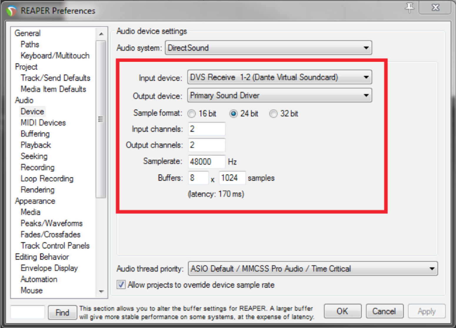
2) Select Options>Preferences.
3) Select Devices in the Audio menu.
4) Select DVS Receive 1-2 (Dante Virtual Soundcard) for the input device.
5) Select your Sample Rate (48000), Bit Depth (24 bit), and Channels and then Select OK.
6) Select Track>Insert New Track.
7) Select input source. Assign Input:Mono>Left to this track
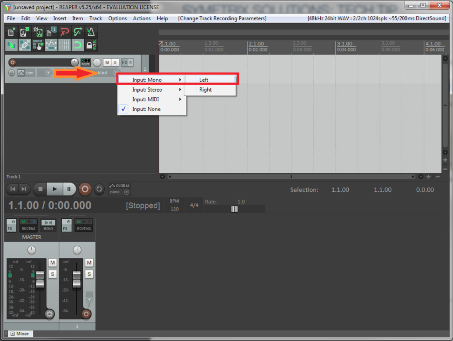
8) Insert another track. Track>Insert New Track
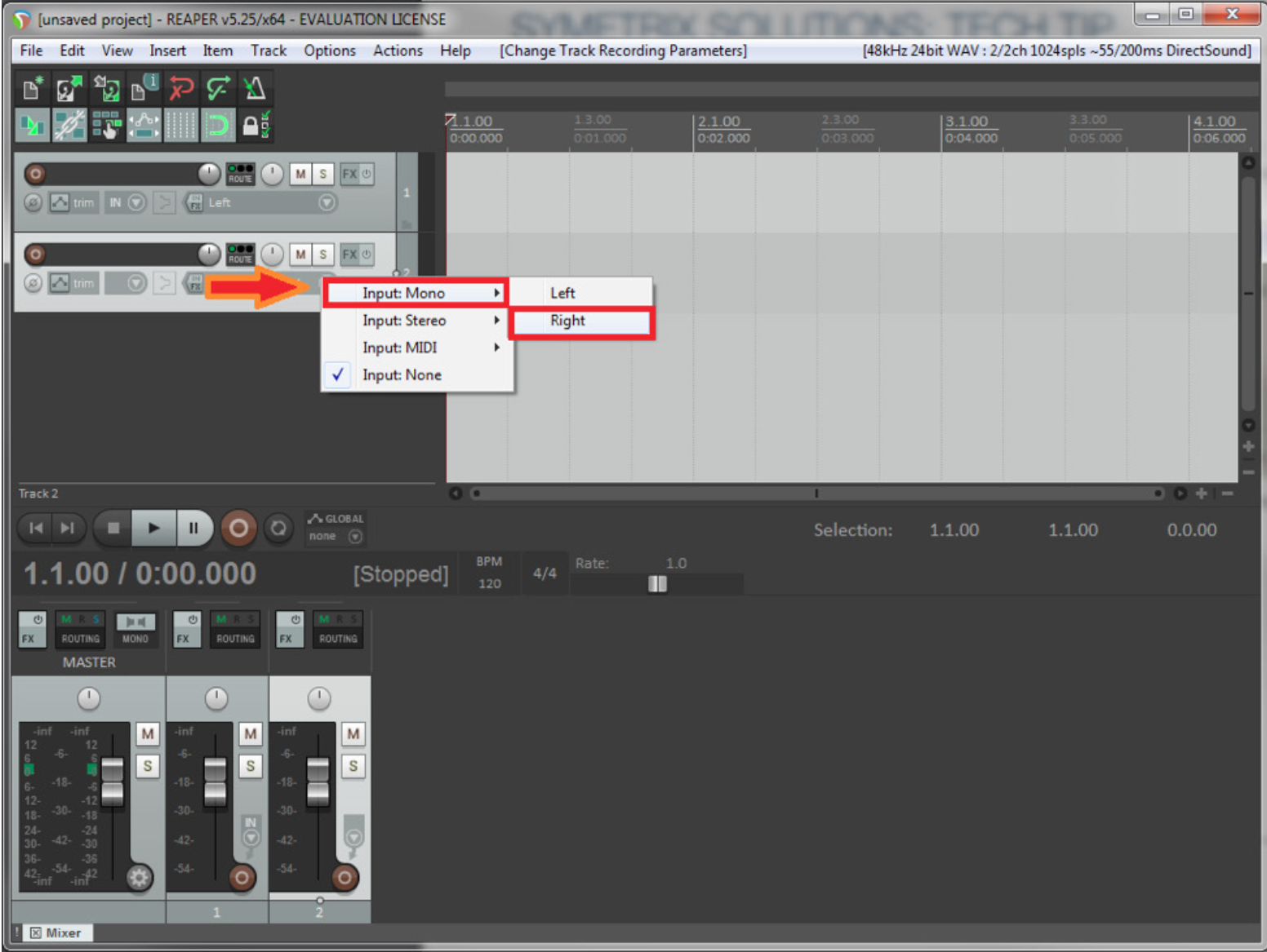
9) Select input source. Assign Input:Mono>Right to this track.
10) Select and Arm each track. You should now see your audio metering in the Record window.
11) Select Record.
12) You can now record the audio from the Dante Bus to your recording software.
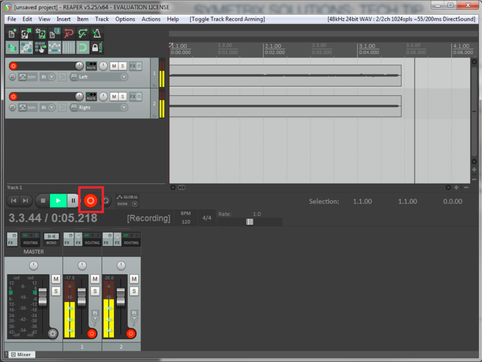
Note: Most recording software use WDM for 2 channels/tracks only (left and right), while ASIO is used for multi-channel/track recording. So, if you only need to record in stereo or 2 channels/tracks WDM will be fine. If you need to record 3 or more channels/tracks use ASIO.
This tech tip will walk through the necessary steps required to receive audio in an Edge, Prism, or Radius NX DSP from the Dante Virtual Soundcard running on a PC or MAC laptop.
The Dante Virtual Soundcard software allows a PC or Mac to connect to a Dante audio network. Dante Virtual Soundcard uses the Ethernet port on the computer to communicate with a network of other Dante enabled devices. No special hardware is required other than installing Dante Virtual Soundcard on a conventional PC or laptop. Audio applications use the Dante Virtual Soundcard as they would any standard ASIO or Core Audio sound card. Sending audio from your laptop to the DSP using Dante has many benefits including but not limited to: testing the Dante network, sending test tones or pink noise to the DSP outputs, and tuning the speakers with known audio content. Another application might be to play recorded content in an audio installation, such as intermission messages or sound effect playback in theaters. There are certainly many other useful applications so be creative.
What you will need:
- Composer
- Edge, Prism, or Radius NX
- Dante Controller (www.audinate.com)
- Dante Virtual Soundcard (DVSC) (www.audinate.com)
- An ASIO capable program such as Cubase, Logic, Sound Forge, Winamp
In this example Winamp will be utilized as it is a free download available on the web. From the Winamp website the ASIO Output Plugin will also need to be downloaded.
1) Open Winamp and go to Options->Preferences (Ctrl + P).
2) Next, click on Output section of “Plug-ins” and choose the “ASIO Output Plugin [out_asio.dll]” to select the ASIO driver for Winamp.
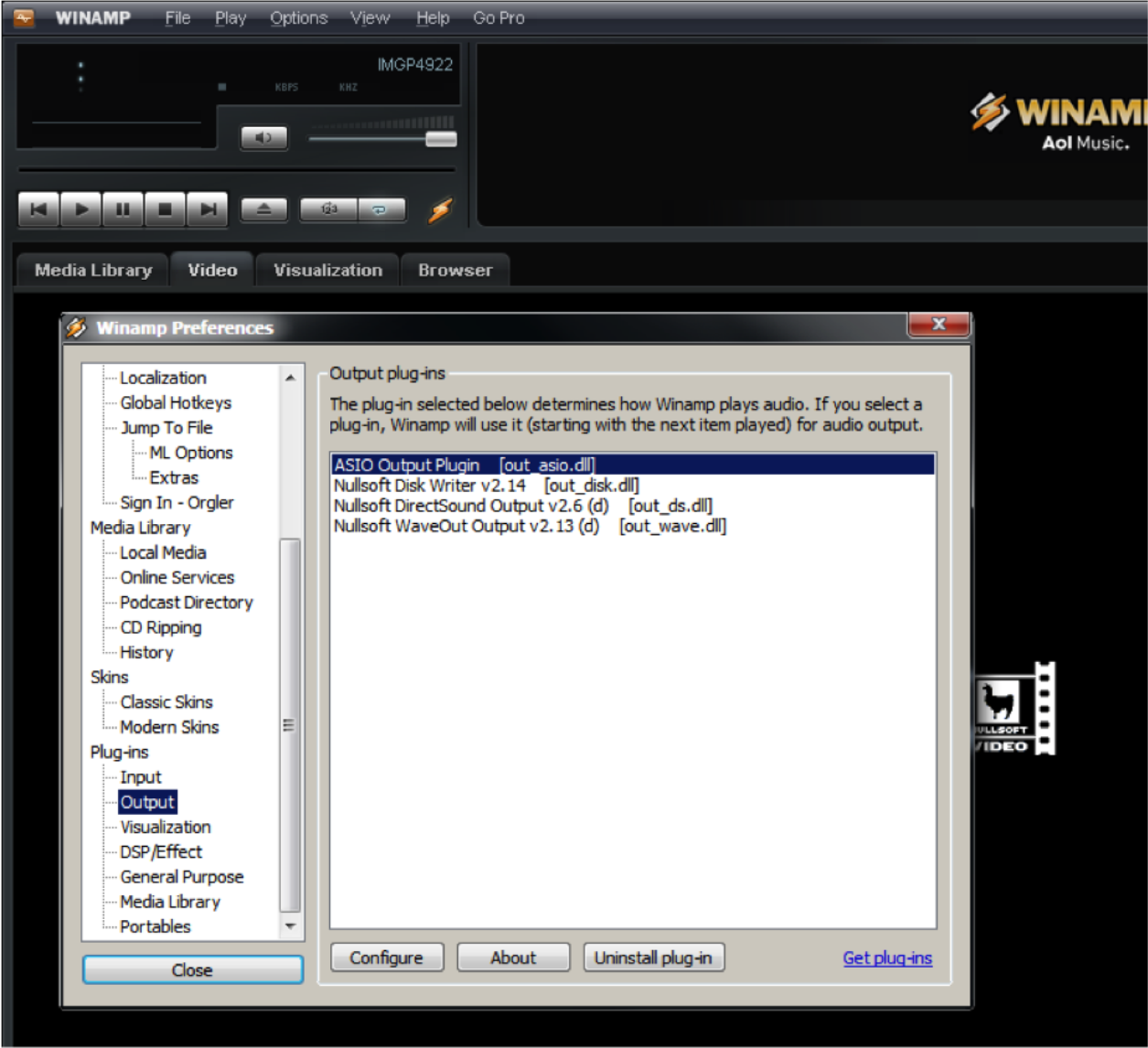
3) The Config ASIO dialog will pop up, and the Dante Virtual Soundcard will need to be selected.
ra 1
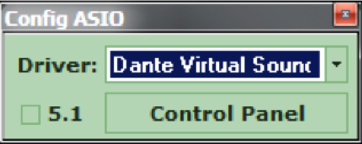
3) The Config ASIO dialog will pop up, and the Dante Virtual Soundcard will need to be selected.
4) Launch the Dante Virtual Soundcard by clicking the Control Panel button.
5) Turn on the Dante Virtual Soundcard by clicking the Power button. It will turn green when active.
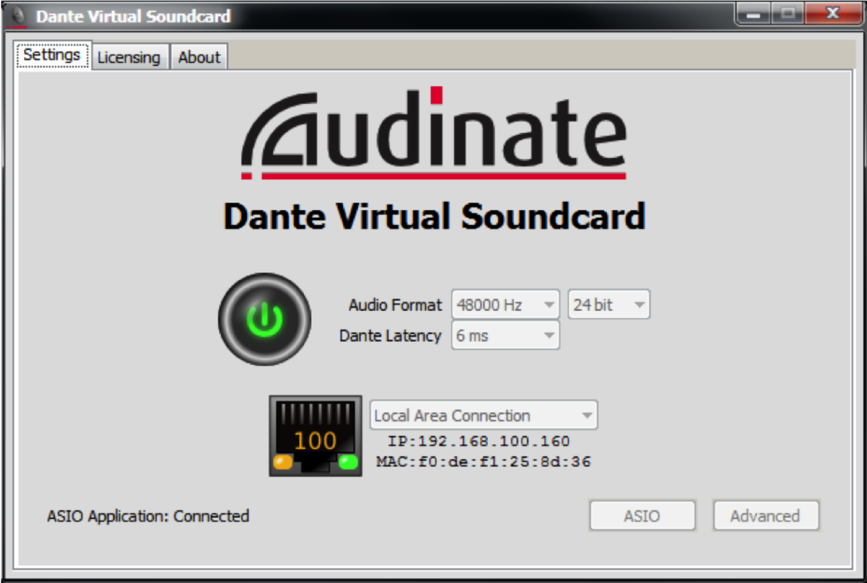
6) Open Dante Controller located at Start->All Programs->Audinate->Dante C controller.
7) The Dante Device Network Name of the PC or MAC running the Dante Virtual Soundcard (DVSC) should be visible on the Routing page. In this example the name of the Dante network device is rcurtright-lap1. Write this name down for a later step.
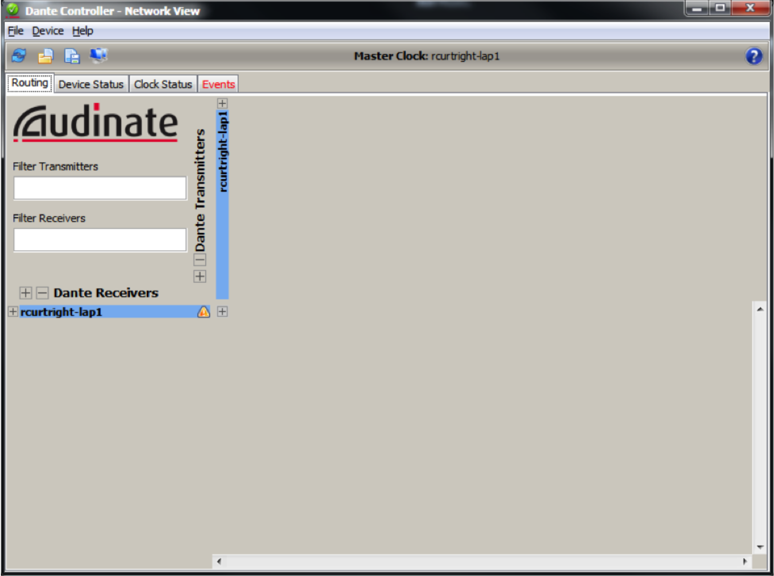
8) Next, click on the Device Status tab, and then double click on the device name. In this case it is rcurtright-lap1. This will launch the Dante Controller Device View.
9) Click on the Transmit tab and then label all channels which you would like to receive in the Edge or Radius.
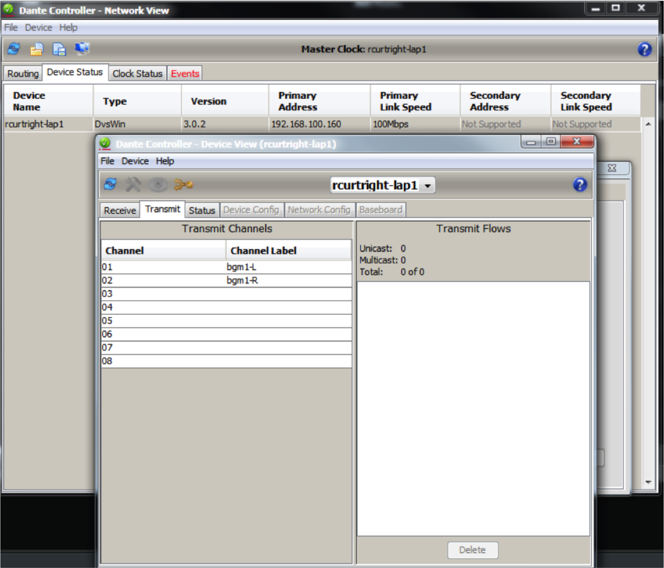
Since Winamp is being used, only 2 channels are needed to carry a stereo signal which has been named bgm1-L and bgm1-R in this example.
10) Now, on the Routing tab, expand the device in the upper area of Dante Transmitters and confirm that the two named channels are now listed.
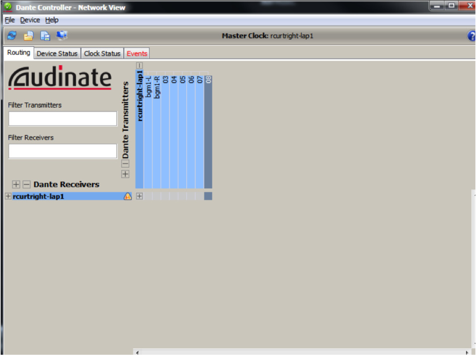
11) Next, open Composer, locate hardware (Ctrl+Shift+L), and then enter the design view by double clicking on the Edge or Radius DSP icon.
12) In the Toolkit expand “Dante Transmit and Receive Flows” and drag a New Transmit/Receive Flow into the design.
13) A new Dante flow will be created and Dante Flow Module Properties will pop-up.
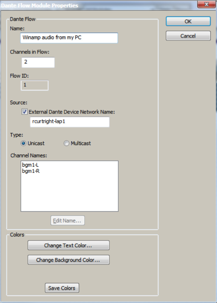
- Name for new Dante Flow: can be anything and is only for organization in C composer.
- Channels in Flow: can be 1-8 channels, although this examples uses 2 for stereo content from Winamp.
- Place Dante Flow Module: set to receive.
- Source: check the box for External Dante Device Network Name and enter the network device name from step 7. It must be typed exactly as displayed including any special characters or spaces in the name.
- Type: unicast.
- Channel names: name both channels with exactly the same names given in step 9 using Dante Controller.
14)Wire the Dante modules outputs into any module input or analog output. In this example Dante is wired into a stereo matrix mixer.
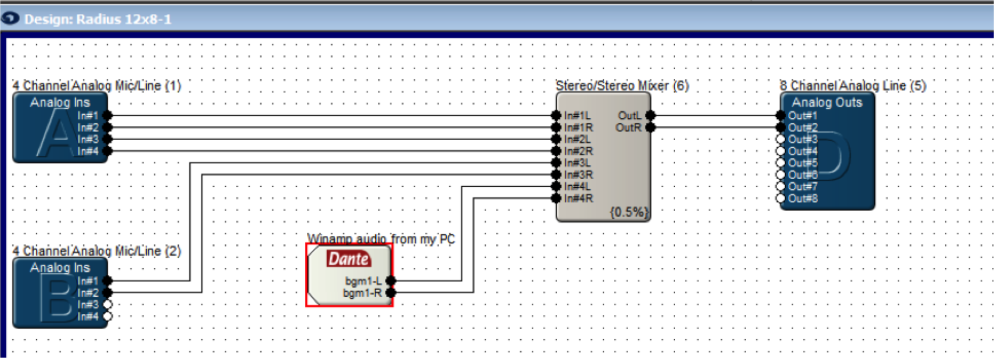
15) Push the site file to hardware.
16) In Dante Controller on the Routing Tab with Dante Receives and Dante Transmitters expanded the Edge, Prism, or Radius NX DSP should now show a connection between the DVSC channels.
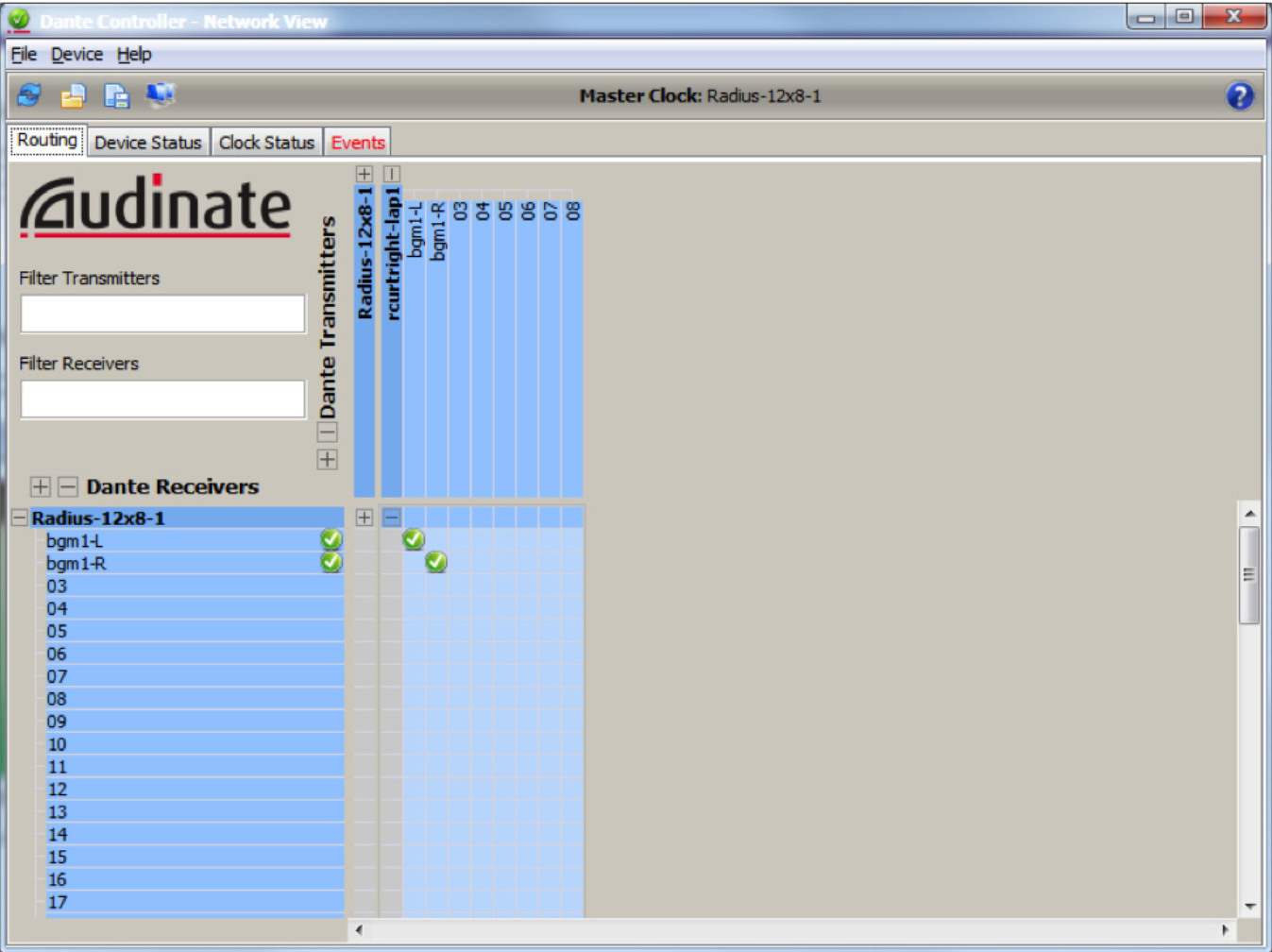
17) In Composer opening the GUI for the Dante Flow should show audio on the meters, as long as a song is currently playing in Winamp.
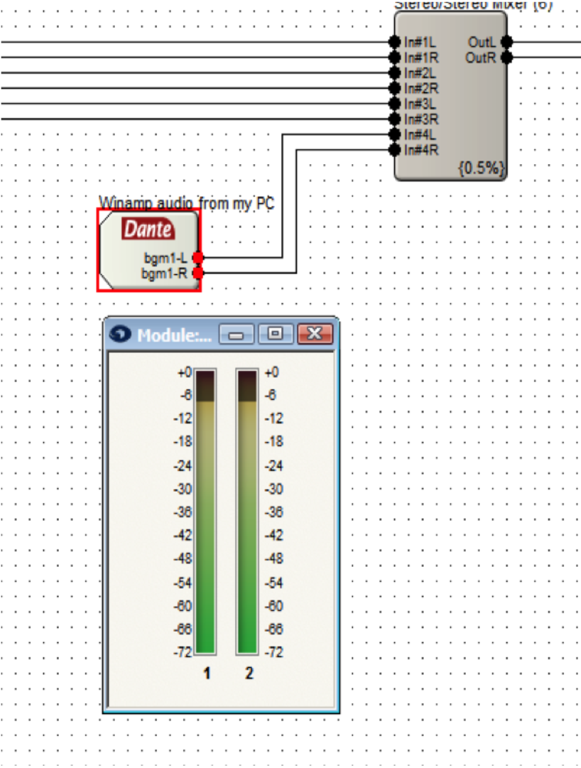
Note: setting Winamp to repeat a song or to playlist is suggested for continuous audio.
Note: Dante network audio is 24bit / 48khz audio. This means that playing a mp3 in Winamp which is 16bit / 44.1khz audio will cause it to be pitch shifted due to the 44.1khz audio being played at 48khz by the device. For true testing purposes use software that can play 24bit / 48khz audio, a common example being Sound Forge.
Composer, Symetrix next generation DSP platform, has arrived and is in full effect. Composer software manages all aspects of Dante DSP devices including audio, control, and security with an intuitive drag and drop CAD-style interface that previous users of SymNet Designer will feel right at home working with.
That being said, a Symetrix guru might feel a little out of water designing, commissioning, and/or troubleshooting the new Dante digital audio buss used by all audio devices in the Composer platform. Currently both Edge and Radius units are the two DSP frames implementing Dante as the network audio buss, and yes, more Dante hardware will be forthcoming in the Composer family. Both Edge and Radius units have the ability to transmit and receive 64 x 64 channels of Dante audio thanks to the installed Dante Brooklyn II card.
The good news is that the method for adding Dante flows to the design in Composer is exactly the same as adding SymLink or CobraNet in SymNet Designer. However, if you are reading this document, then it is time to understand Dante and be comfortable designing, using, and troubleshooting a Dante network, because in the not so far away future SymLink and CobraNet will be a thing of the past.
First, let’s get to know Dante a bit better and understand why Symetrix chose to use Dante as its digital audio buss in Composer hardware.
What is Dante?
Audinate’s patent pending Dante™ technology is a flexible Internet Protocol (IP) and Ethernet based digital AV network technology that eliminates the many bulky cables needed to provide point-to-point wiring for analog AV installations.
With Dante, existing infrastructures can be used for high performance audio as well as for ordinary control, monitoring or business data traffic. Digital networks utilize standard Ethernet over IP offering high bandwidth capable of transporting hundreds of high quality channels over 100MBs or 1 Gigabit Ethernet.
Set-up and configuring the system is made easy as well, saving enormous installation costs and long term cost of ownership on a digital network. The physical connecting point is irrelevant: audio signals can be made available anywhere and everywhere. Patching and routing now become logical functions configured in software, not via physical wired links.
Benefits of Using Dante Digital Networks:
- Cost savings for audio distribution system – no need for heavy, expensive copper analog cable
- Separates logical and physical connections
- Any number of I/Os can connect to the network without bulky cables
- Actual connections managed by software
- Large bandwidth capability over a single cable
- Improved audio quality- Does not suffer from hum, ground loops, or audio quality degradation experienced with conventional with long cable runs
- Integrated media and control- Control signals can be included on the network without additional cabling
- Leverage off the shelf IT equipment to take full advantage of IT industry developments in functionality, reliability, availability and cost savings.
- Any Dante capable device can share audio with any other Dante capable device regardless of the brand or manufacturer.
Network Considerations:
Dante is based upon universally accepted networking standards and does not require special networking infrastructure. Dante enabled devices can be connected using inexpensive off-the-shelf Ethernet switches and cabling. In the ideal situation, the Dante network switches will be:
- Gigabit ports for inter-switch connections
- Quality of Service (QoS) with 4 queues
- Diffserv (DSCP) QoS, with strict priority
- A managed switch to provide detailed information about the operation of each network link: port speed, error counters, bandwidth used, etc. A managed switch can also be used to filter unicast from multicast Dante flows.
While Dante can theoretically work on any network switch to some capacity, the above criteria should be the norm when designing your Dante network infrastructure. Of course, these considerations are not needed if Edge or Radius units are set to “Switch Mode” and the Dante ports are daisy chained between devices.
Gigabit vs.100Mbps network switch topology:
While Gigabit switches are recommended, 100Mbps switches may be used in limited scenarios.
- For low channel count (< 32 channels) applications, a 100Mbps switch may be used as long as it supports proper QoS, and QoS is active. The use of 100Mbps switches without QoS is not recommended or supported.
- For higher channel count (32 – 1,024 channels) applications, Gigabit switches are essential. QoS is recommended for Gigabit switches on networks that share data with services other than Dante.
Unicast vs. Multicast:
Symetrix Dante DSP devices have the option of sending Dante audio as either unicast (point-to-point) or multicast (network-wide broadcast) flows. Unicast flows are point-to-point and use roughly 1 Mbps of network bandwidth per channel making it is possible to have 1,024 channels of unicast Dante audio on a Gigabit switch. Multicast Dante audio uses significantly more network bandwidth than unicast Dante, so how do we know when to use multicast flows?
When particular audio channel or group of audio channels are being sent to multiple receivers (typically three or more) it is more efficient to use available network bandwidth to send a single multicast packet to many receivers than to send individual packets with identical payloads to each receiver.
All Ethernet switches support multicast. Dante doesn’t need special multicast features from network switches but at the same time it is designed to work efficiently with advanced multicast features like IGMP Snooping.
Troubleshooting Dante:
“Dante just works” is Audinate’s slogan and catch phrase for Dante, and for the most part it is true. That being said, our customers want to know what to check and what steps should be taken if Dante does not “just work”.
Dante Resources:
Before going onsite to setup, test, or troubleshoot a Dante network, it is advised that you download the listed resources and read the following sections on network configuration and troubleshooting steps.
Tech Tip: How to Receive Audio in Edge/Radius From DVS (Dante Virtual Soundcard)
https://www.symetrix.co/wp-content/uploads/2012/09/2012-09-DVS.pdf
Tech Tip: Recording Audio with Dante
https://www.symetrix.co/wp-content/uploads/2012/09/2012-10-Record-Audio-Dante.pdf
Dante Controller: Like Composer, this is software you absolutely must have before going onsite!
http://www.audinate.com/index.php?option=com content&view=article&id=305
Dante Virtual Soundcard (DVS): While not necessary, is an awesome tool to add to your arsenal for setting up, testing, or troubleshooting Dante networks. (Free 14 day trial)
http://www.audinate.com/index.php?option=com_content&view=article&id=238
Dante FAQ: Audinate has a great FAQ for Dante. It may be helpful to bookmark this page for later reference.
http://dev.audinate.com/kb/webhelp/home.htm
Network switch topology and configuration questions and answers:
(questions are numbered, answers are alphabetical following each question or questions)
- What mode is the Symetrix Dante device set to; Switch or Redundant mode?
a. In all Dante testing scenarios, troubleshooting scenarios, or during initial setup of the Dante network, all units should be in “Switched mode” with only the primary port of each unit connected to the network switch or daisy-chained from Primary to Secondary port of the Symetrix devices.
b. If a redundant Dante network is needed, first get audio passing between hardware in Switched mode, and once successful use Composer to change the Dante Mode to Redundant in the Dante Flow Manager. Lastly connect the secondary Dante ports to the redundant network switch. - Is the switch Gigabit?
- Is this a dedicated Dante network?
a. If the answer to either question 2 or 3 is “NO”, then we must make sure that QoS is configured.
In other words, if the network is 100Mbps or it has shared data other than Dante on the network, then QoS is not an option, it is a necessity.
Qos (Quality of Service) is a feature of managed switches, which ensures that certain types of network packets (e.g. clock sync and audio packets) get preferential treatment and are “moved to the front of the line” ahead of other traffic. This is achieved by attaching a priority number to each packet, which is then used by the switches to ensure that high priority packets get processed before lower priority packets.
QoS settings:
1. QoS mode: Basic
2. Trust Mode: DSCP
Most problems related to QoS arise when the Trust Mode is set to COS (class of service”) instead of DSCP. COS is often the initial QoS trust mode setting and does not work with Dante.
Troubleshooting steps:
The following steps assume that Dante flows have been set up in Composer and pushed to hardware, and yet Dante audio is not passing between devices.
- M make sure all Dante flows were created correctly in Composer. Open the Dante Flow Manager. Click on each Dante flow and insure that all flows are transmitted from a unit, as well as received in at least one other unit. An exception to this is when transmitting or receiving audio to or from a 3rd party Dante enabled device.
Note: transmit device in Red, receiving devices in Green.
- U use the front panel to verify that all devices are on the same Dante Mode. Remember, it is advised by Symetrix to keep all units in Switched Mode with only a primary port connected to the network until Dante is passing.
- If the Dante devices are distributed across a network with multiple switch hops, minimize the network hops. Certainly if Dante will not pass from one port to another on a single network switch, it obviously won’t make it through 10 switch hops across a network.
a. Direct connect two or more Edge, Prism, or Radius unit’s Dante ports together without a network switch.
Does Dante pass?
i. If Dante passes with a dir
ect connect, the Dante ports are functioning. Go to b.
ii. If Dante does not pass with a dir
ect connect, contact Symetrix support.
b. C connect the Dante port of each unit to a LAN port on the same network switch.
i. If Dante passes through one switch, check to make sure all network switches are the same model and are configured to the same settings. If different models of network switches are being used, perform this test on each network switch individually.
ii. If Dante does not pass from one LAN port to another on the same switch, check to make sure QoS is active and set to DSCP . Then connect a PC to a LAN port on the same switch and launch Dante Controller.
c. U use Dante Controller to check the routing and network configuration.
i. Routing page:
ii. Does DanteController show the units connected to the switch?
1. If Dante Controller does not show both units, direct connect the PC s LAN port to the Dante primary port and check if Dante Controller can see the device.
iii. Does Dante Controller show green checks between flows.
1. If yes and audio is not passing, check the network switch QoS settings.
2. If there is no check or Red Xs, is it possible to create the link with Dante Controller by clicking the cross point?
3. Make sure that the names of the channels match, if they do not match, check the flow in Composer and name the channels.
d. Clock Status: Dante Controller will show which device is a master and which is a slave. Only one Dante device should be the master. If there is more than one master, check network switch settings and make sure both units are on the same subnet.
e. Are the units on a Gigabit or 100Mbps network? Dante Controller can report the link speed.
The number of channels that can traverse one link in a network is proportional to the link speed. A link will always slow down to the lowest speed connector on that link; for example if a Gigabit port on switch A is connected to a 100Mbps port on switch B, the link speed will be 100Mbps. This is good, because it allows you to mix link speeds in a network without having to do anything complicated.
Naturally the faster the links in your network, the higher the performance, and for this reason we recommend that you use gigabit Ethernet as much as possible, especially when switches are being linked together. Many Dante enabled devices use Gigabit Ethernet interfaces, including Edge and Radius, for this reason it is a good idea to use gigabit switches throughout your Dante network.
If Dante Controller reports 100Mbps link speed:
- There must be less than 32 Dante channels on the network switch.
- QoS must be active and trust mode set to DSCP.
In order to conclude this Tech Tip on Dante, it is useful to discuss one aspect of Dante and how it relates to other digital audio protocols, namely VOIP.
Dante makes use of standard Voice over IP (VOIP) Quality of Service (QoS) switch features, to prioritize clock sync and audio traffic over other network traffic. VOIP QoS features are available in a variety of inexpensive and enterprise Ethernet switches.
The first thing to note is that VOIP does not equal Dante.
It may be tempting to draw a correlation between Dante and VOIP due to the fact that QoS, which was designed to prioritize data on a network, is most often associated with VOIP systems. However, there are many VOIP networks that do not use QoS. This makes it very tempting to say, “VOIP is working fine on this network without QoS, so Dante should be able to work on this same network without QoS.”
This is simply not true. Correlation does not equal causation. VOIP and Dante only share some similarities, however Dante uses much more complicated communications which monitors and synchs the audio latency across all Dante enabled units, as well as supplying clock to all Dante units. VOIP does nothing of the sort.
Further, remember networks with shared data other than Dante must have QoS turned on.
The purpose of the Tech Tip is to assist with the implementation of the CLOCKAUDIO CDT100 into Dante enabled Composer based audio systems.
The CLOCKAUDIO Dante Transporter (CDT100) is a Dante communication product which combines audio and control transport using network based Dante protocol. By taking advantage of the advanced Dante technology and based on the high performance and pre-configurable hardware platform, this product transfers audio and control signals via Ethernet and is able to achieve extremely high sound quality.
The CDT100 has a variety of uses including but not limited to boardrooms, conference rooms, video conference rooms and any place else where multiple table microphones and control devices are connected back to the AV equipment cabinet.
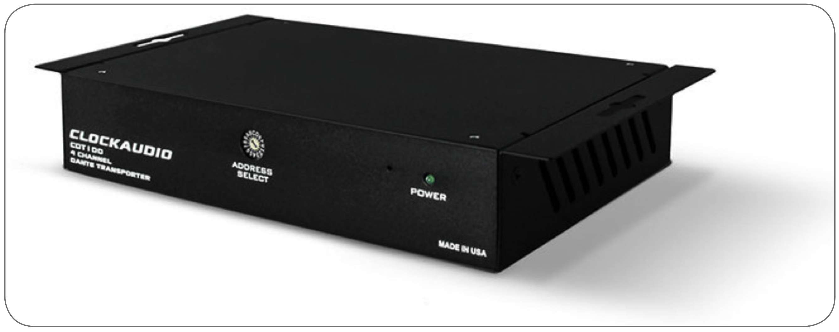
One of the features of Composer is Third-party Dante Device integration. The CLOCKAUDIO CDT100 is among the list of available Third-party Dante devices.
Here are the steps to create the CDT100 Dante audio flows within Composer:
- Make sure all the devices (DSP, xI/O, ect) in the site file are running matching Composer firmware (must be Composer version 4.1 or newer).
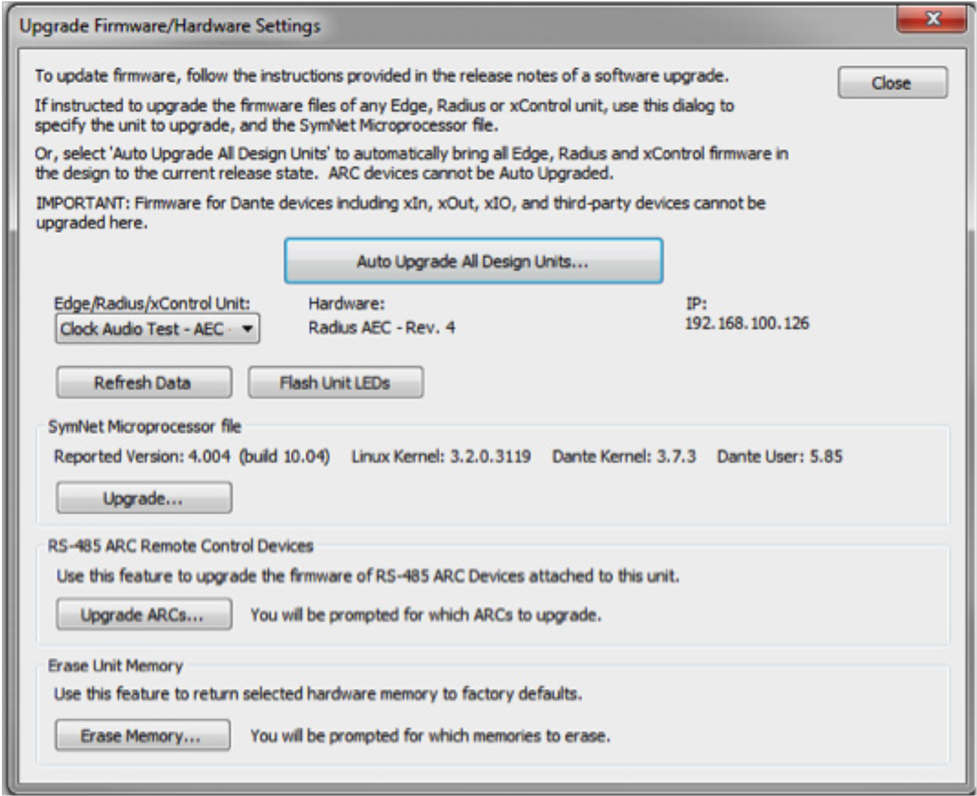
CDT 1
2. Drag a CDT100 from the Toolkit to the site design (Third-party Dante Devices>CLOCKAUDIO).
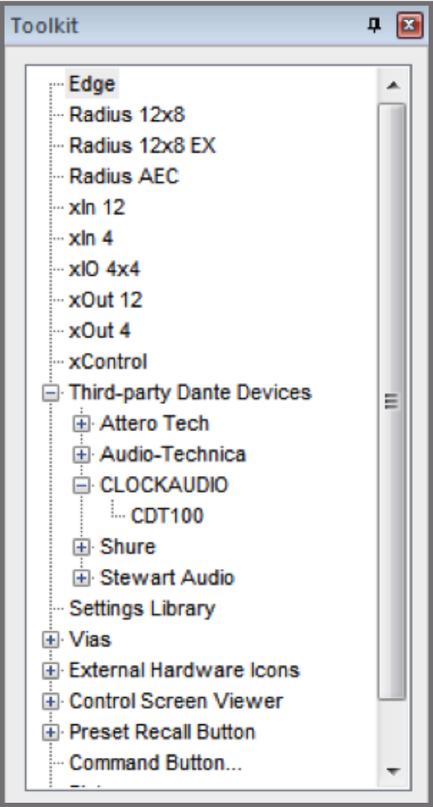
CDT 2
3. Locate all units in site file.
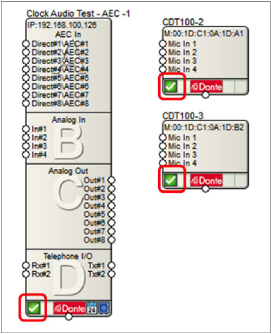
CDT 2
4. Right-click on the CDT100 and select “Configure CLOCKAUDIO Inputs…”
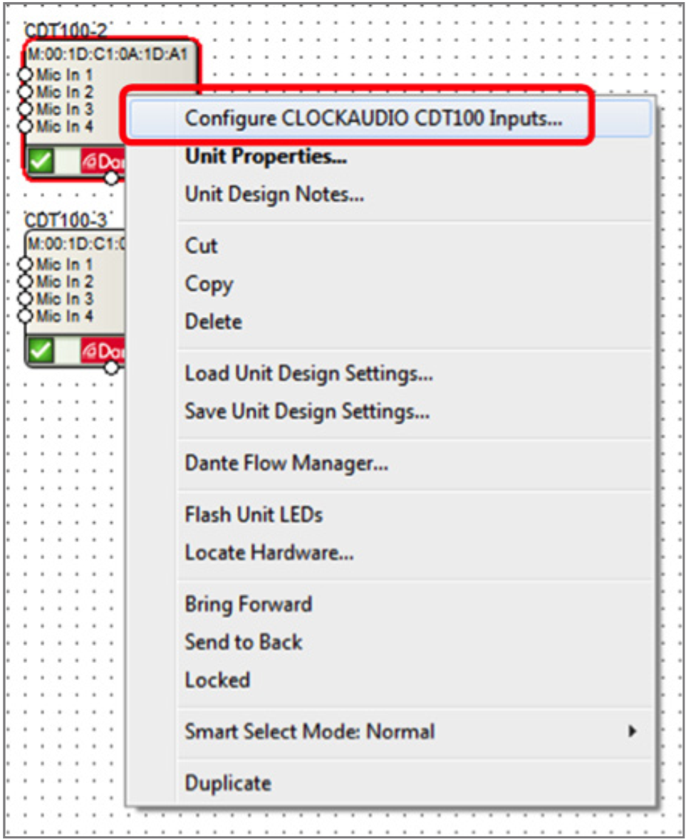
CDT 3
5. Check the box for Phantom if the microphone on that channel requires phantom power
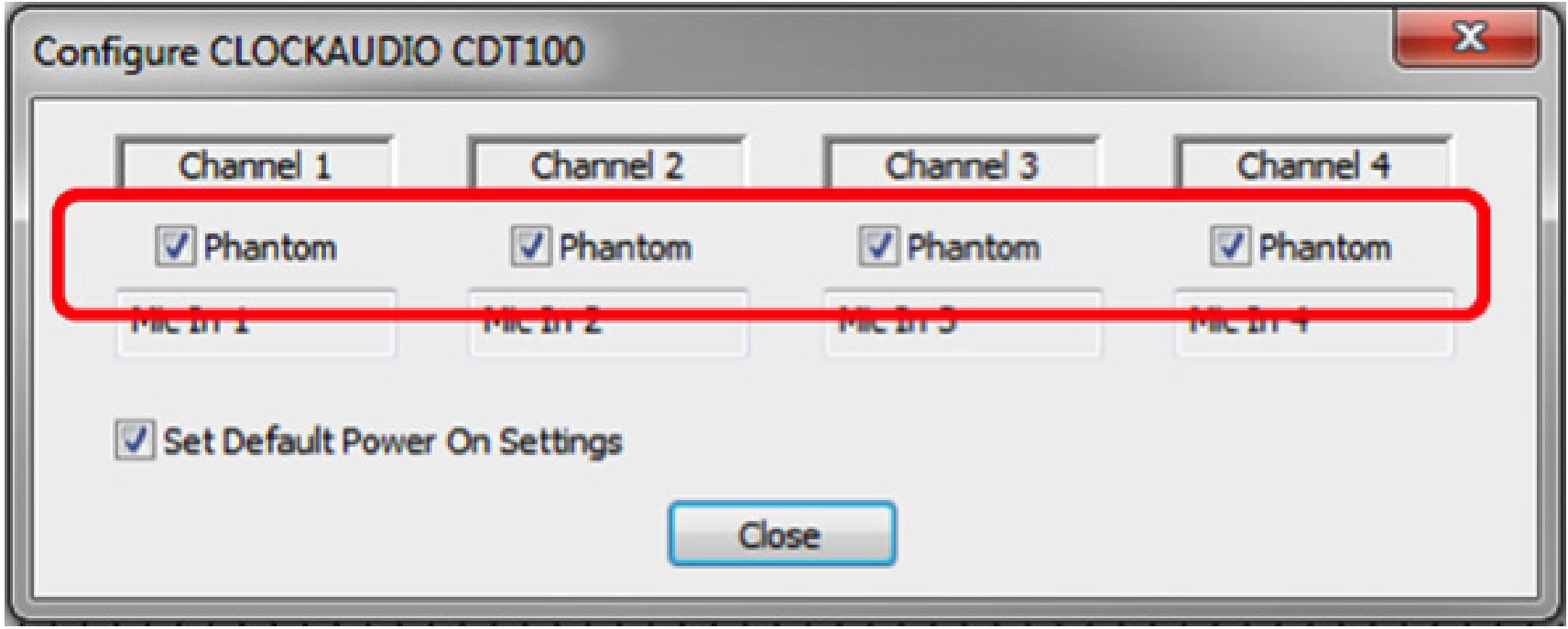
6. Double click on DSP and open site design
CDT 4
7. From Toolkit drag in a new receive flow for the CDT100 (Dante Transmit and Receive Flows>Receive Flow Modules for Existing Flows>Untitled CDT100 Flow).
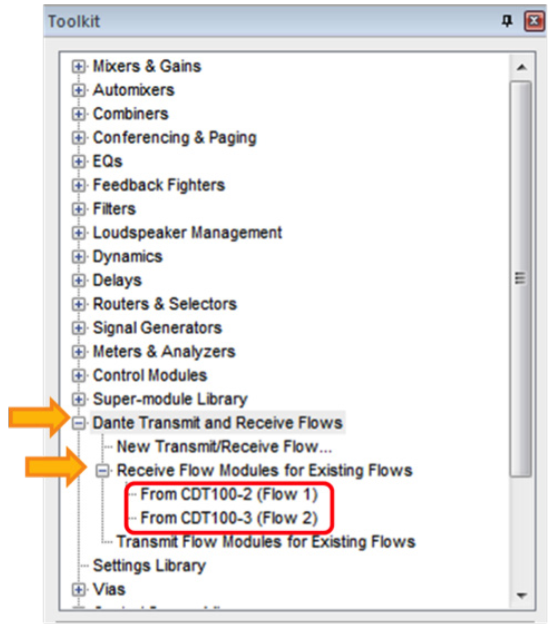
CDT 5
8. Wire the system design for the desired signal processing and routing.
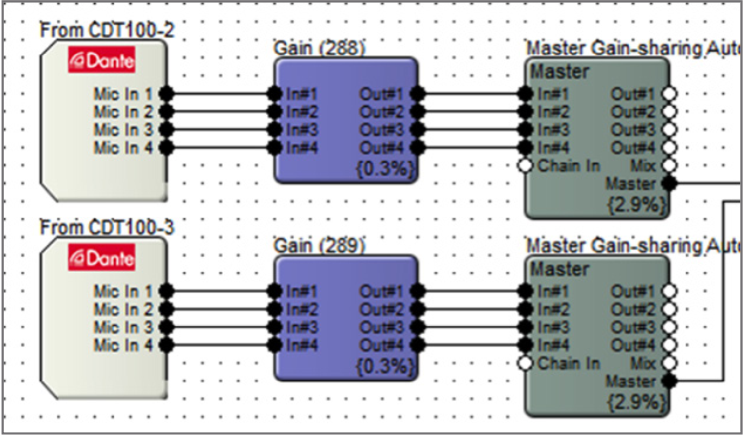
9. Close the design view and return to the site view.
10. Push the site file and go on-line.
Here are the steps to create the CDT100 Dante control features within Composer:
- After adding, locating and creating the Dante audio flow for the CDT100, the next step is to configure the control transport.
CDT 7
2. Drag in a 4-Button Momentary module from the Toolkit (Control Modules>Control Inputs).
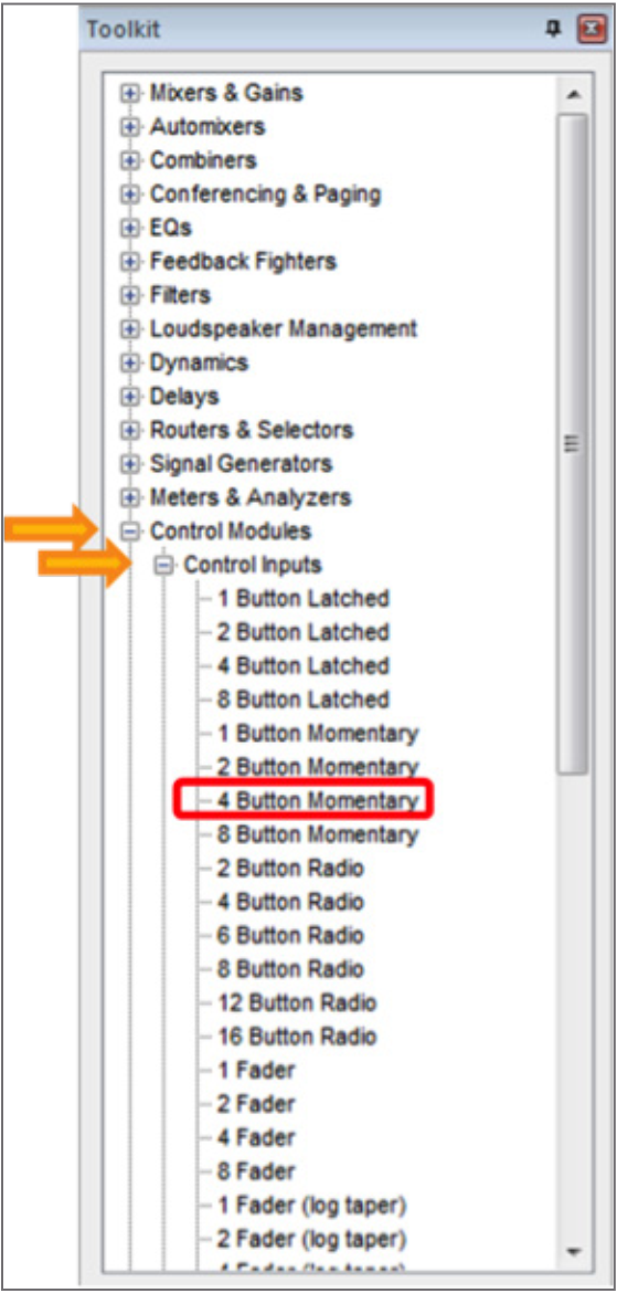
CDT 8
4. Drag in a 4-Button Processor Super-module (Super-module Library>Import super-module).
- With ARM-C use the CDT100 Processor or CDT100 Processor w/Unmute Delay from 3rd Party Control folder.
- Without ARM-C use the 4-Button Processor from Tools folder.
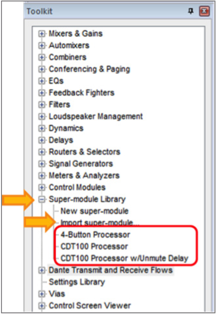
CDT 9
5. Wire the output of the 4-Button Momentary to the input of the 4-Button Processor.
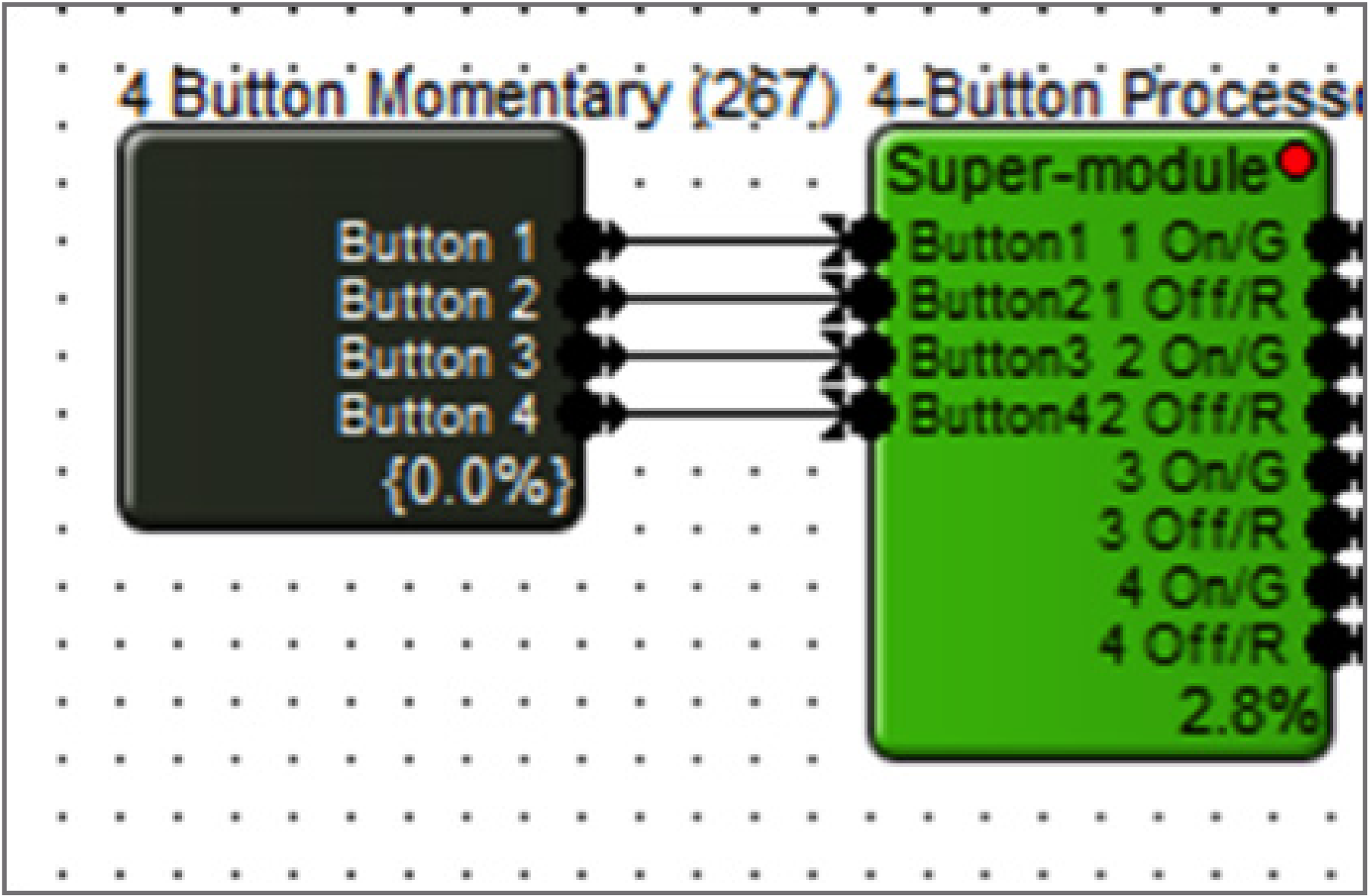
CDT 10
6. Drag in a Remote Logic Output (Control Modules>Control Outputs).
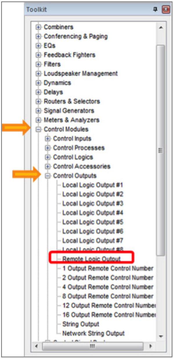
CDT11
7. Select the CDT100 for Remote Unit.
8. Select the Green LED #1.
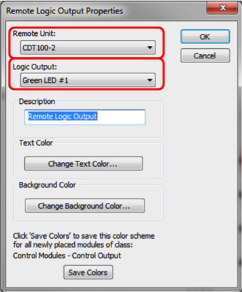
CDT 12
9. Drag in a Remote Logic Output (Control Modules>Control Outputs).

CDT 1
10. Select the CDT100 for Remote Unit.
11. Select the Red LED #1.

CDT 14
12. Wire the output of the 4-Button Processor (1 On/G) to the G Remote Logic Output.
13. Wire the output of the 4-Button Processor (1 Off/R) to the R Remote Logic Output.
14. Repeat steps 5-12 for each remaining button.
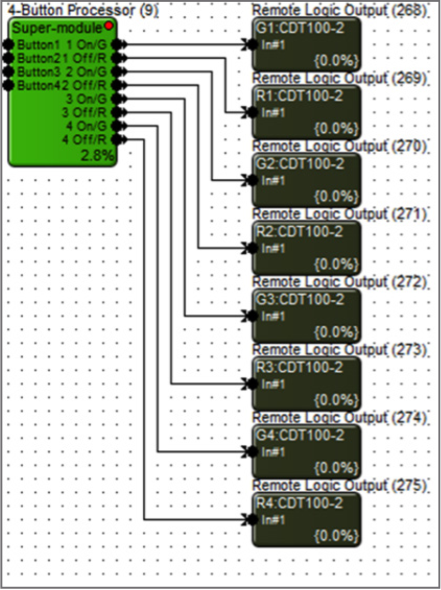
15. When using ARM-C, select ARM-C for the Logic Output in the Remote Logic Output Properties.
CDT 15
16. Wire the output of the 4-Button Processor (ARM-C) to the Remote Logic Output.
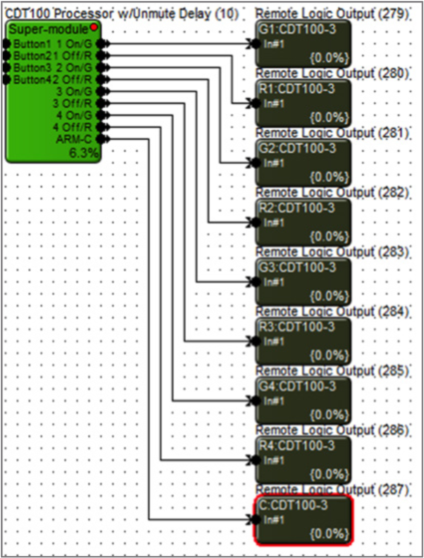
CDT 16
17. Double click and open either a Gain Module or Automixer used in the signal processing and routing of the microphones.
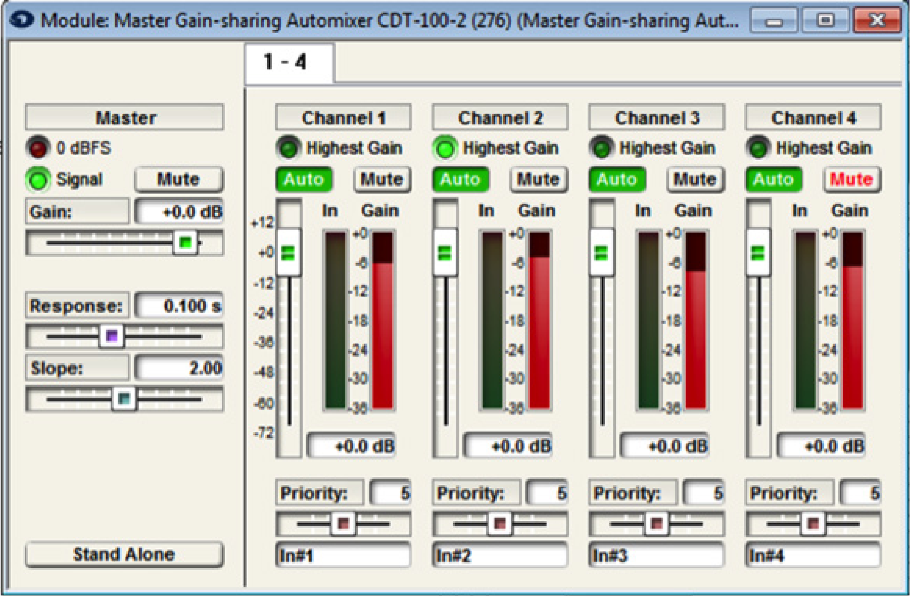
CDT 16
18. Right-click on the Channel 1 Mute button.
19. Select “Set Up Remote Control”.
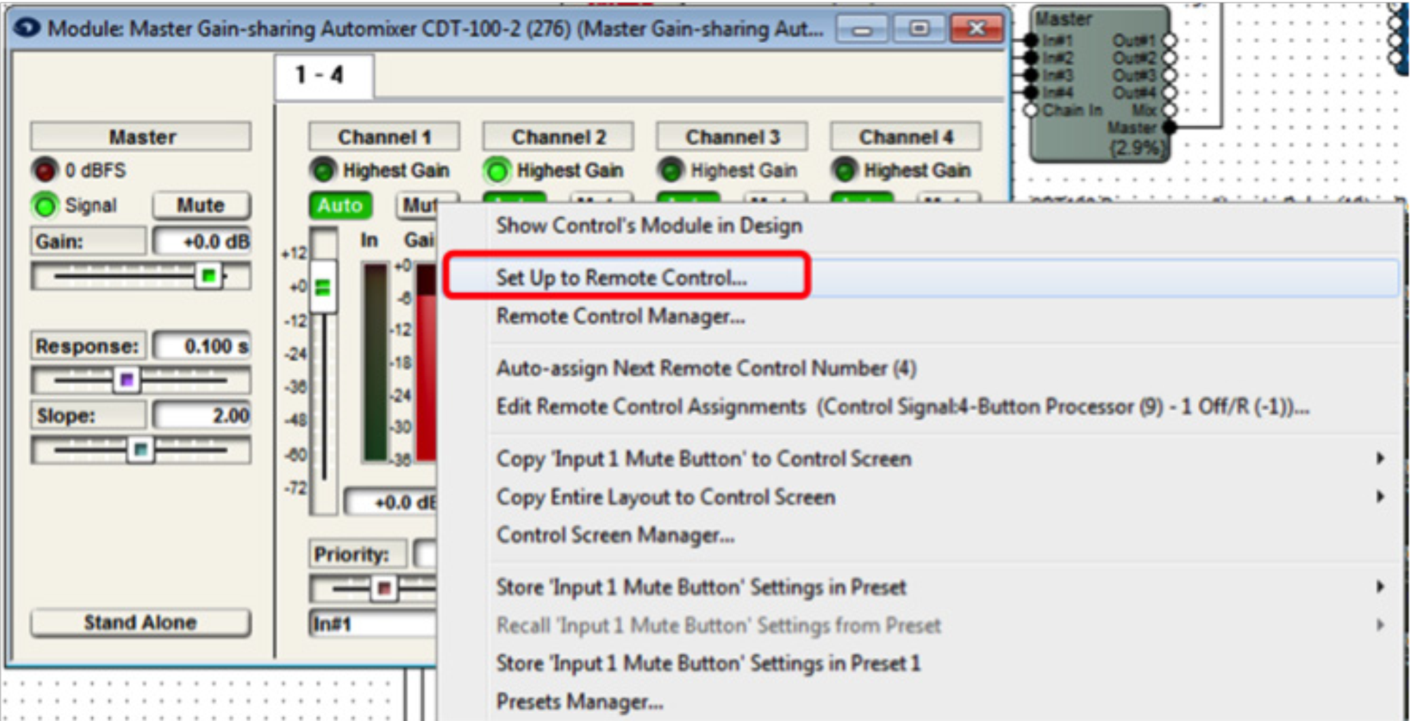
CDT 17
20. Select “Control Signal Assignment” for the Remote Control Device
21. Then click “Select”.
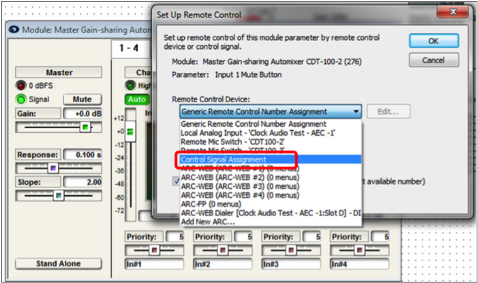
CDT 18
22. Expand 4-Button Processor.
23. Select 1 Off/R.
24. Click OK.
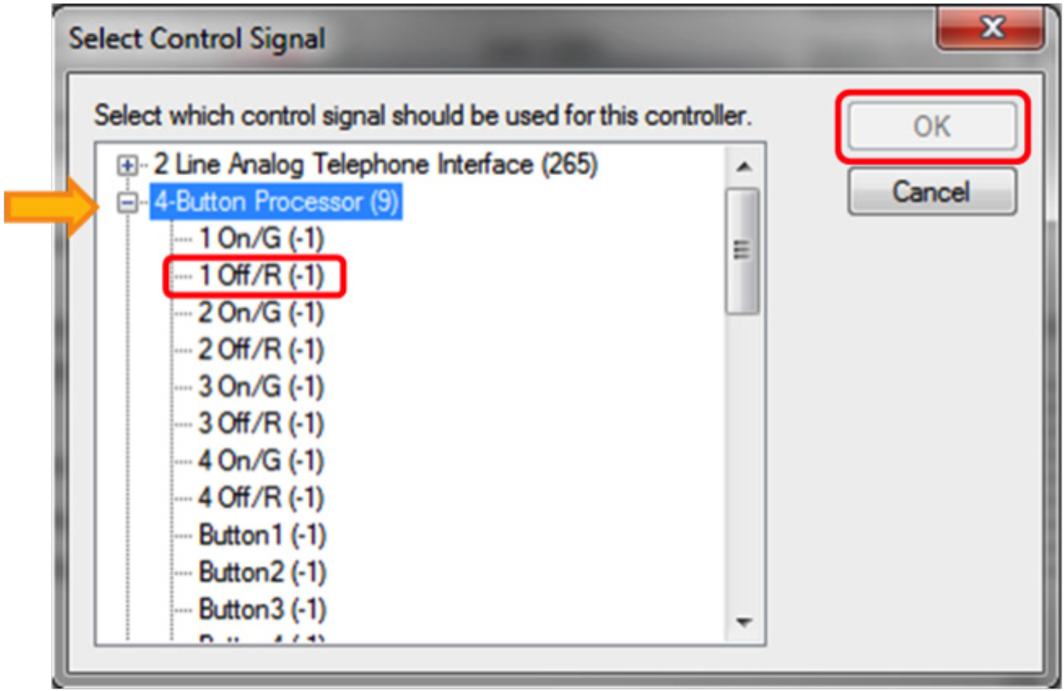
The mute button of the Automixer will now be controlled by the state of the red LED of the super-module. When the red LED is active, that channel will be muted. When the red LED is inactive, the channel will be unmuted. Repeat steps 17-24 for each microphone channel. Assigning the Mute button of each microphone channel to its corresponding x Off/R output of the 4-Button Processor.
CDT 19
25. Double click and open the 4-Button Momentary module.
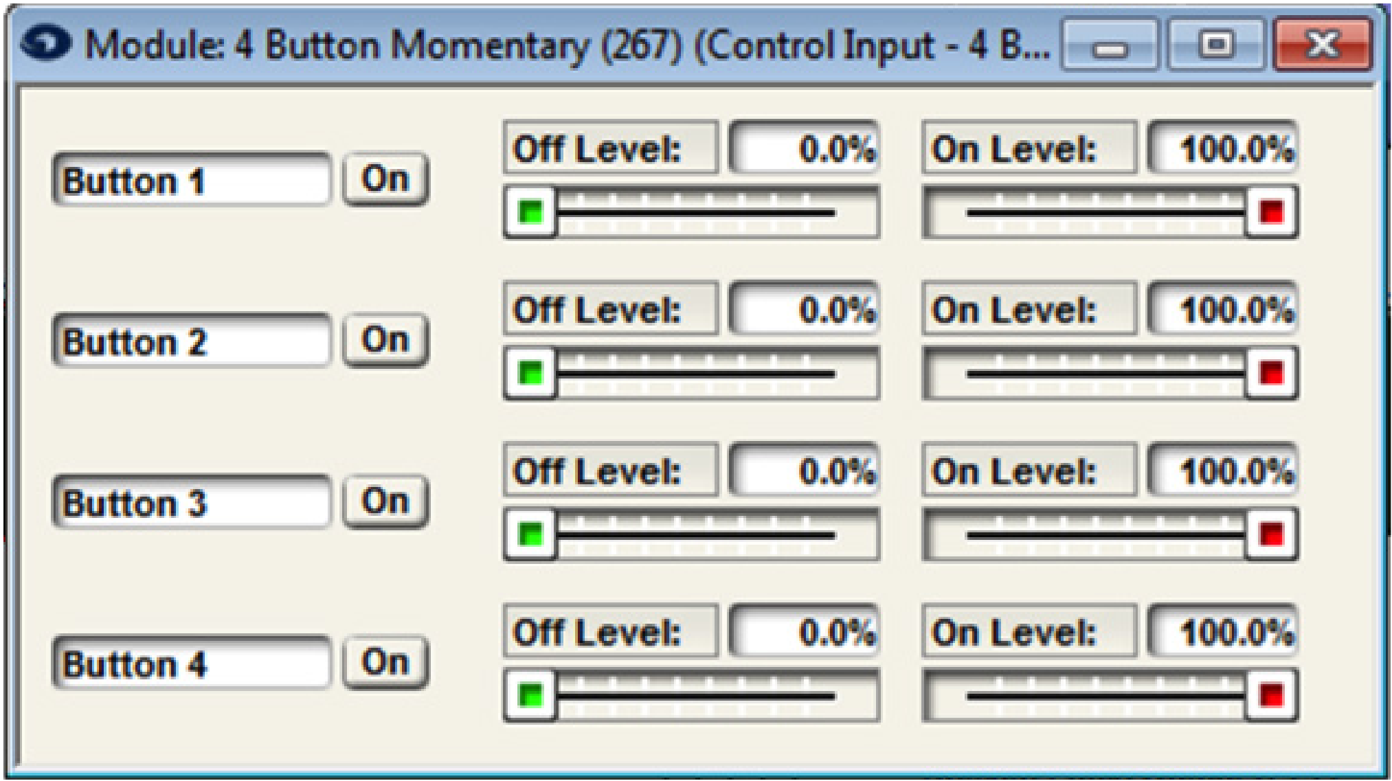
CDT 20
26. Right-click the “On” button for Button 1.
27. Select “Set Up Remote Control”.
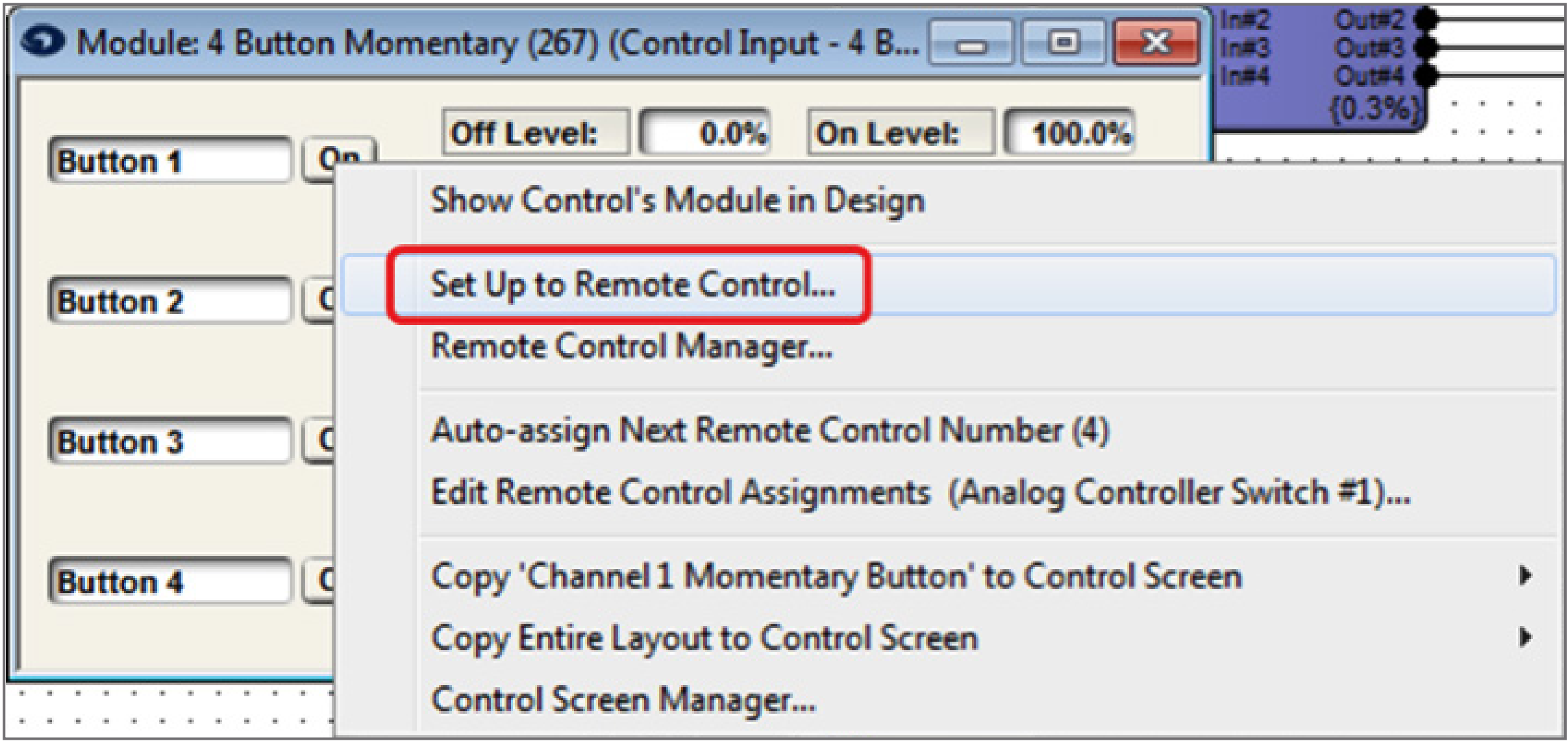
CDT 21
28. Select “Remote Mic Switch-‘CDT100’” for the Remote Control Device.
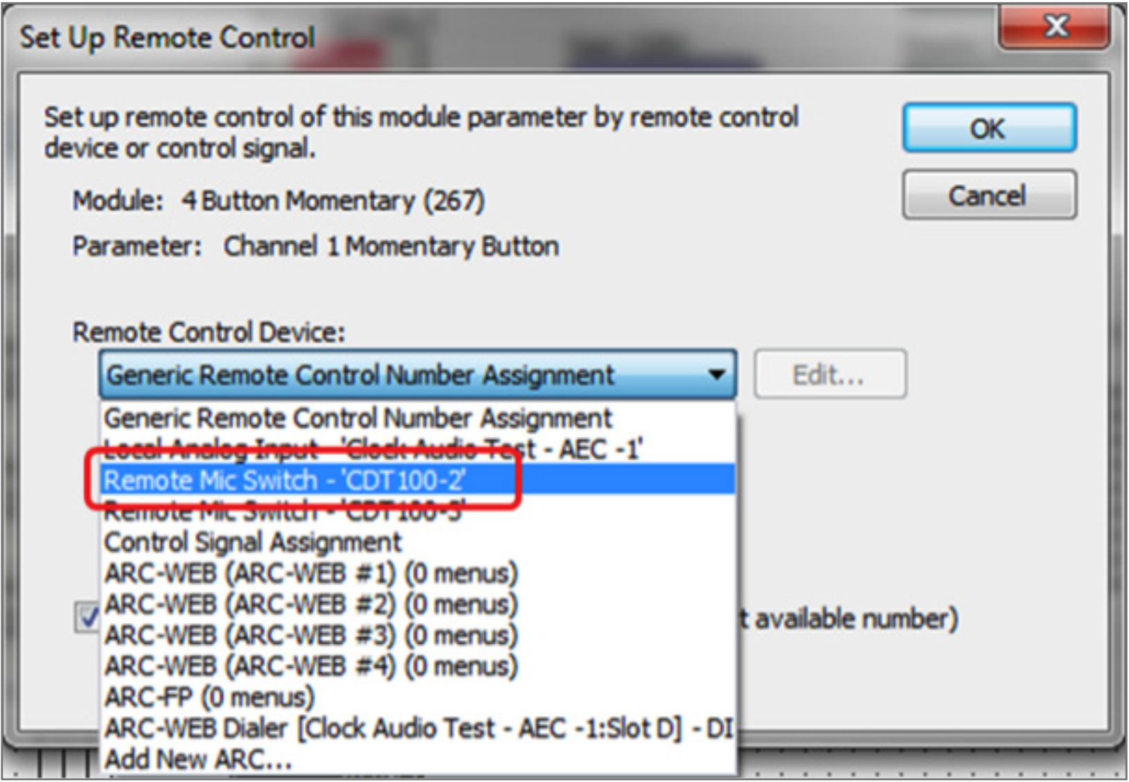
CDT 22
29. Select “Switch #1” for the Select Analog Control.
30. Click OK.
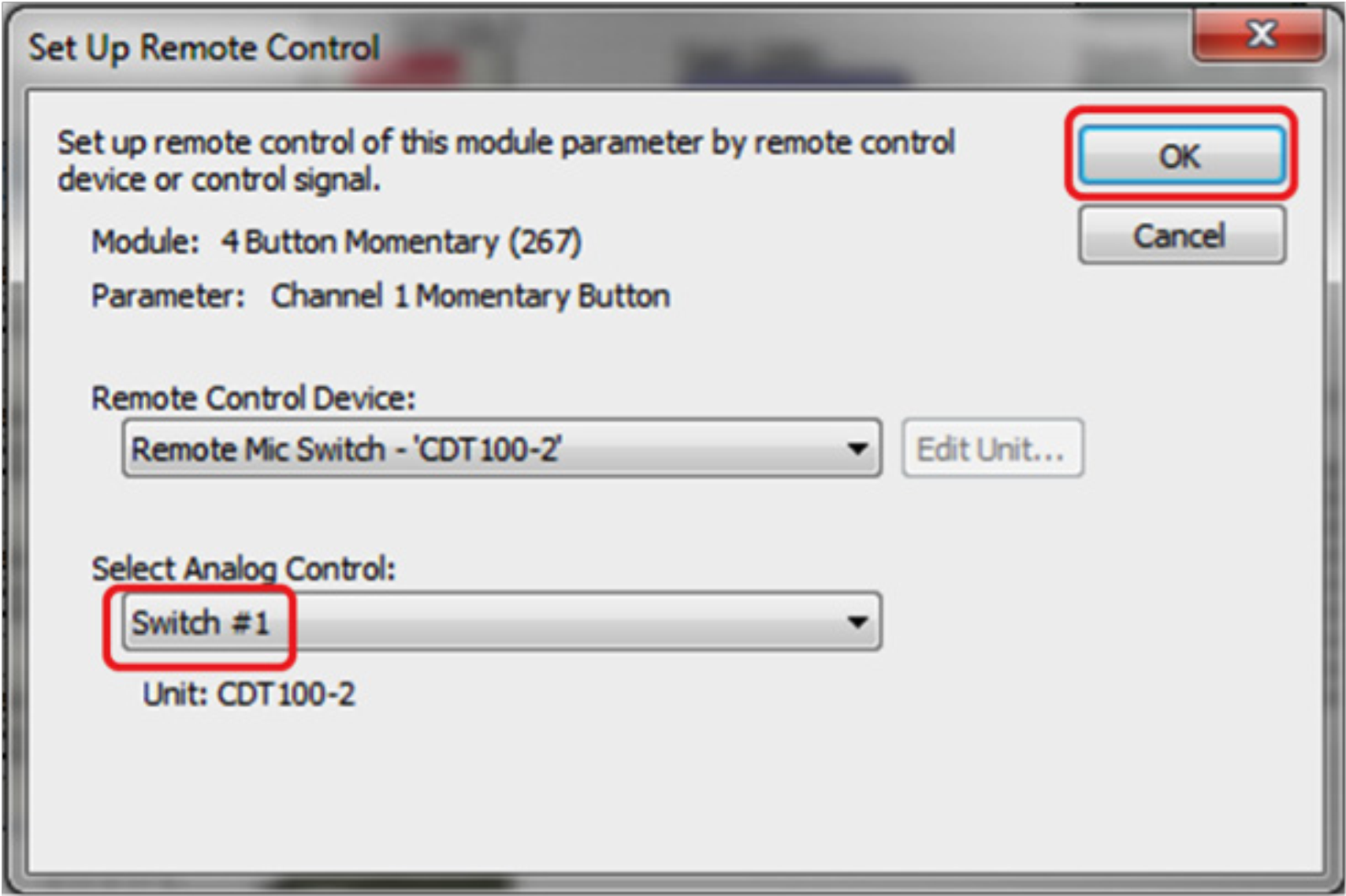
CDT 23
31. Repeat steps 26-30 for each button of the 4-Button Momentary module. Assigning each On button with its corresponding Mic Switch.
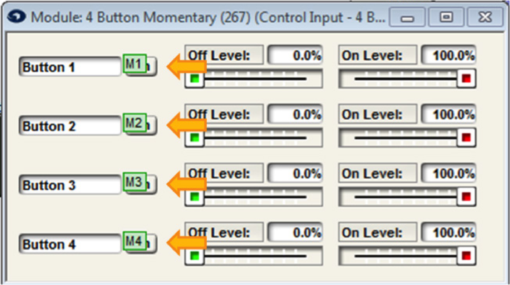
CDT 24
32. Double click the 4-Button Processor to open the Super-module control screen
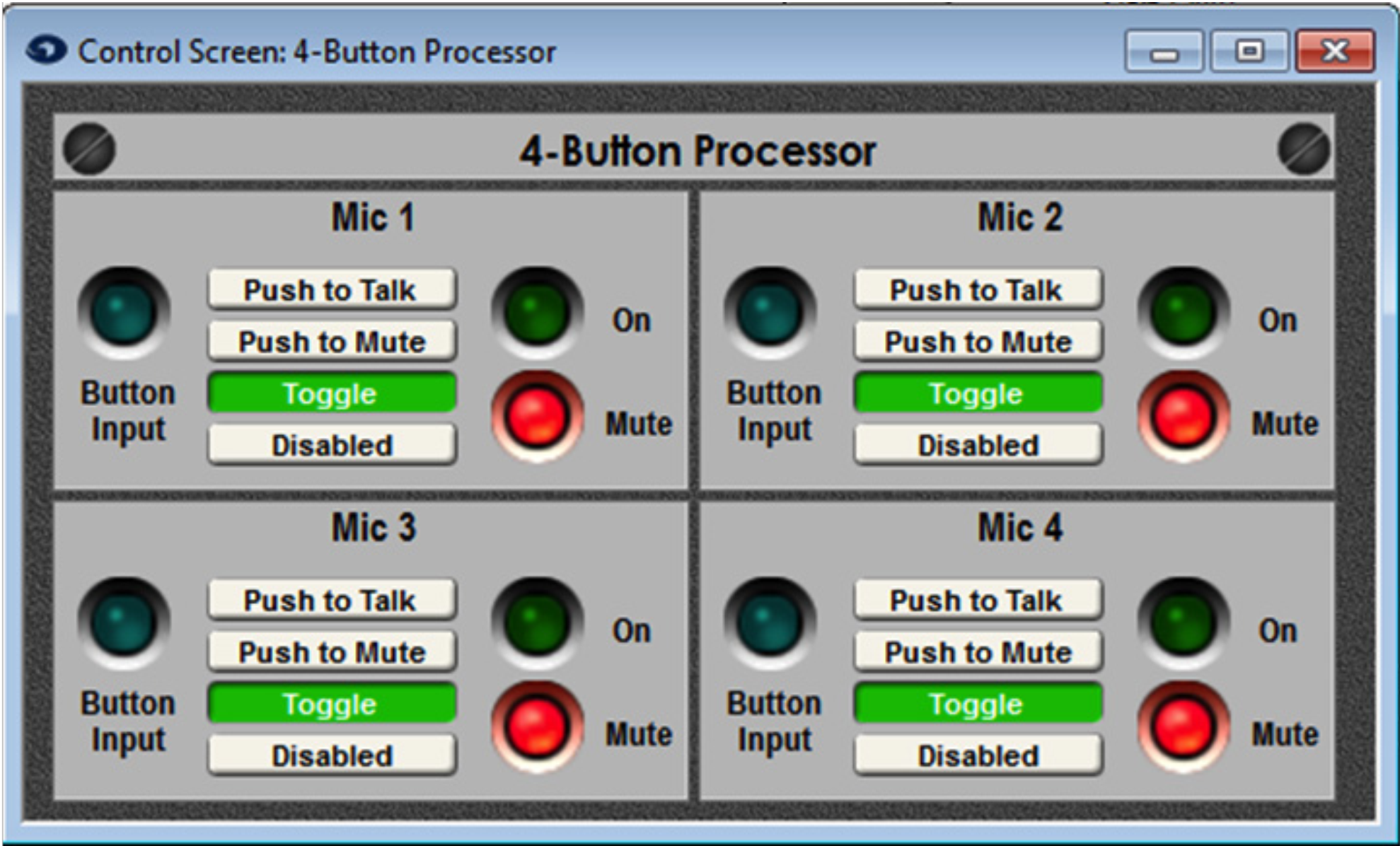
CDT 26
33. Select the desired microphone switch operation (Push to Talk, Push to Mute, Toggle, or Disabled) ARM-C has Radio, Toggle, and Latching controls.
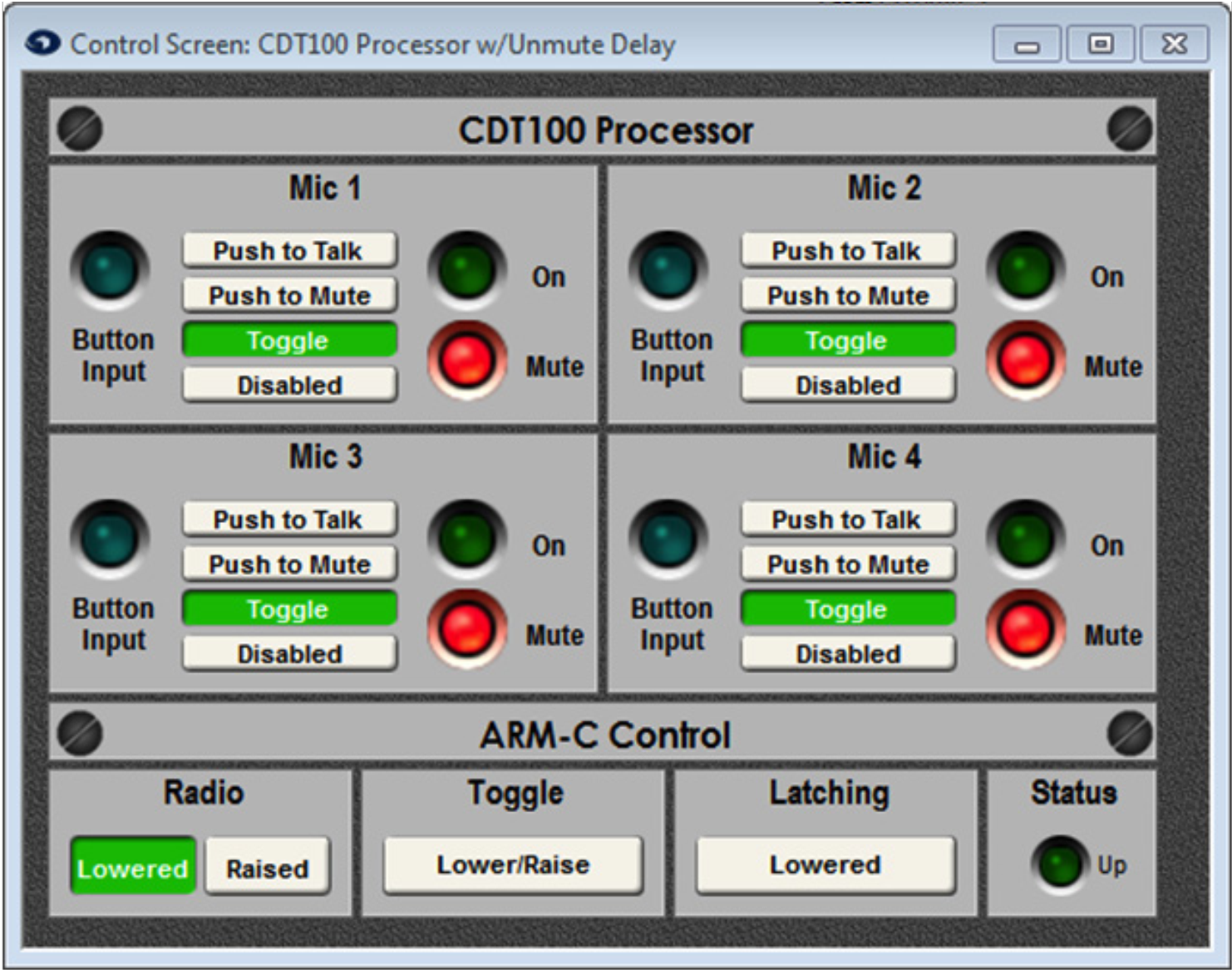
34. Push the site file and go on-line.