


-
Type
- Dante
- Networking
- Control
-
System Management
- Composer Management Software
- SymVue Screen Authoring
- AV-Ops Center Remote Monitoring
- ARC-WEB Control Interface Signal Processing
- D100 AVoIP DSP Server
- Radius NX AVoIP DSP
- Prism AVoIP DSP
- Edge AVoIP DSP
- DSP I/O Expansion Cards
- Jupiter DSP
- Zone Mix 761 DSP I/O Connectivity
- xIO Bluetooth Endpoints
- xIO XLR Endpoints
- xIO AVoIP DSP Audio Expanders Control Systems
- T-Series Touchscreen Controllers
- W-Series Controllers
- Control Server for Personal Devices
- xControl GPIO Expander
- ARC-Series Controllers
Gain Structure: Maximize Dynamic Range, Minimize the Noise Floor in Composer
Product:Composer Management Software
Type: Control
The title of the tech tip says it all. Simply put, having all the DSP in the world is no substitute for proper gain structuring in an audio installation. This is because the gain structure is single handedly responsible for maximizing the dynamic range between the program audio and the noise floor. When the gain structure is set incorrectly, even the best audio equipment with unlimited DSP resources will have audible noise ranging from annoying to unacceptable by the end user. If the gain structure is set correctly, the noise floor should be completely inaudible to the human ear.
The gain structure could be defined as the relationship between various gain stages in the audio system. In a Symetrix DSP system the gain structure is composed of various gain stages within the DSP, the output level of the sources feeding the DSP inputs, as well as the analog input trim on the amplifier. As such, it is important to have a clear understanding of how to correctly adjust each gain stage in the DSP as well as the input trim of the amplifier in order to maximize the dynamic range between the program audio and the noise floor.
When properly adjusting the gain structure, it is important to step through each gain stage, starting at the beginning of the signal path and working to the end.
This is important to note because an older line of thinking, which is responsible for noise in many audio systems, was to start by turning the input trim of the amp to 100% and working backwards through the various gain stages turning them down to compensate for the amp. This method kept unwanted hands from adjusting the amp after the system was tuned, but it also maximized the noise in the system by increasing the noise floor at the amplifier.
Typically there are 3 digital gain stages in the DSP software: input gain, end user gain control, and output gain. Additionally, there may be 2 analog stages outside of the DSP; source gain and amp input trim (depends of the brand of amp), which may need adjusting. Prior to following this step by step tutorial, all gain stages should be left at 0db, which also known as “unity” as this setting does not attenuate the audio up or down.
This tech tip will step you through 9 simple steps to proper set the gain structure in your next audio installation.
Step 1:
Turn off the amp, as it is not necessary to hear the audio when adjusting the first few gain stages.
Step 2:
If needed, set the analog gain of the device feeding the Symetrix DSP input. In most cases the level may not be adjustable; it may be statically set as a mic or line level output. (See the unit’s documentation) For instance, a CD player is a line level output that often has an unbalanced (RCA) connection to the DSP. In the case of a device such as an external mic pre, there may be some gain adjustments that need to be made. In such a case turn the gain up as high as possible without the audio clipping during use. (more on clipping in step 3).
Step 3:
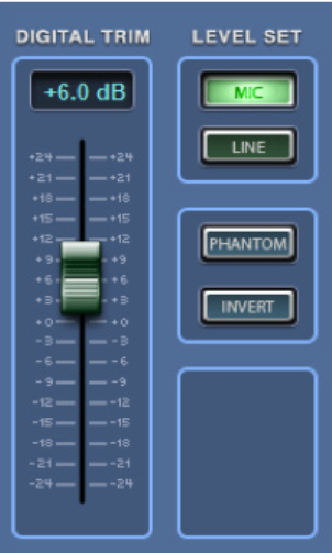
Determine whether the source feeding the DSP input has a line level or mic level signal and make the corresponding selection at the input section of the appropriate software. With the Zone Mix 761, Jupiter, and Solus hardware only mic or line is selected at the input stage. In most SymNet Designer and all Symetrix Composer hardware, 5 selections are available at each input. Line level signals can be balanced (+4dBu) or unbalanced (-10dBV) and have respective settings. Mic level can be -20dBu, 40dBu, and -50dBu. Phantom power should also be turned on when a condenser microphone is used. Radius
units are set to “Switch Mode” and the Dante ports are daisy chained between devices.
gain 1
Zone Mix 761
gain 2
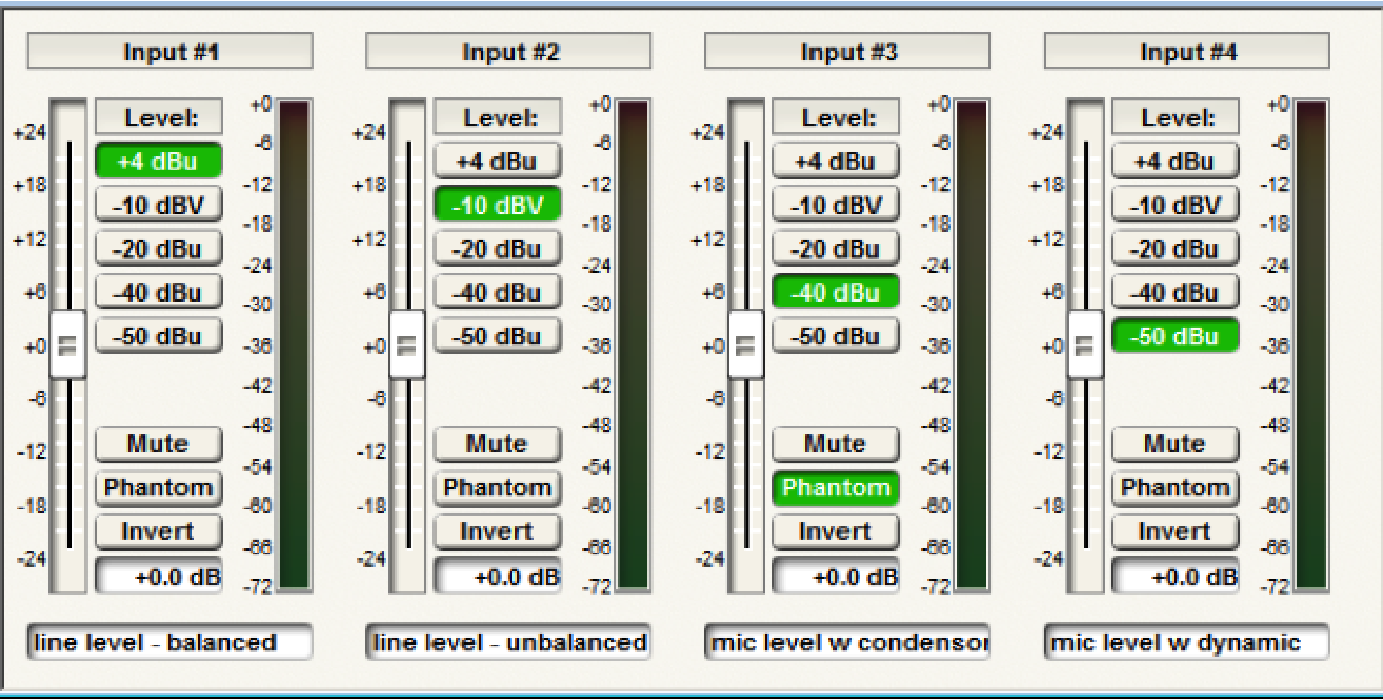
Composer
Step 4:
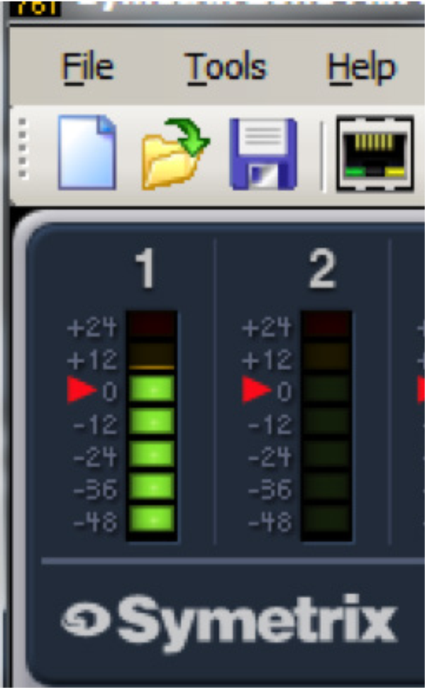
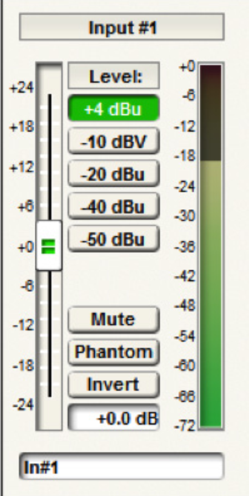
Adjust the input trim in order to maximize gain at the input. Rule #1 is that the input should never clip, which is indicated by the red in the meter. Some audio meters, such as those in the Jupiter software have a range of -48dBu to +24dBu. In SymNet Designer and Symetrix Composer the audio meters are in DBFS and range from -72dbfs to 0dbfs. Clipping is at +24dBu and 0dbfs respectively. When the audio is clipping the signal will be distorted and will almost certainly sound bad. Even worse, clipping audio has the potential to damage hardware including the amps and speakers.
A general rule is that the program audio RMS level, or average level, should reside in the amber portion of the meter while at the same time not clipping. Depending on the meter style, this is somewhere around unity, which is +4dBu or -20dbfs. This setting usually leaves sufficient headroom between the
program audio and the point of clipping so that louder portions of the program audio do not clip, even when the user has the system turned up loud. If clipping does occur, then the input trim should be turned down until the audio stops clipping.
gain 3
Zone Mix 761 Input meter
gain 4
Composer Input meter
Step 5:
Determine which gain control will be given to the end user. Most often this gain control will be in the “middle processing”. Gain adjustments before the input processing can negate or skew processing such as, but not limited to; Compression, AGC, Limiting, and Feedback Elimination. Gain adjustments
after the output processing are not protected by processing such as the Hard Limiter. As such, end user gain control should typically be located between the input and output processing in modules such as a Mixer, Automixer, Room Combiner, or a Matrix.
Once this gain stage has been located, turn it up to +12dB. This will be the “loudest” setting possible that the end user will be able to set the system to. By tuning the system to this “loudest” gain setting, the end user will never be able to turn up the system to the point it causing clipping or damages the amp or speakers.
gain 5
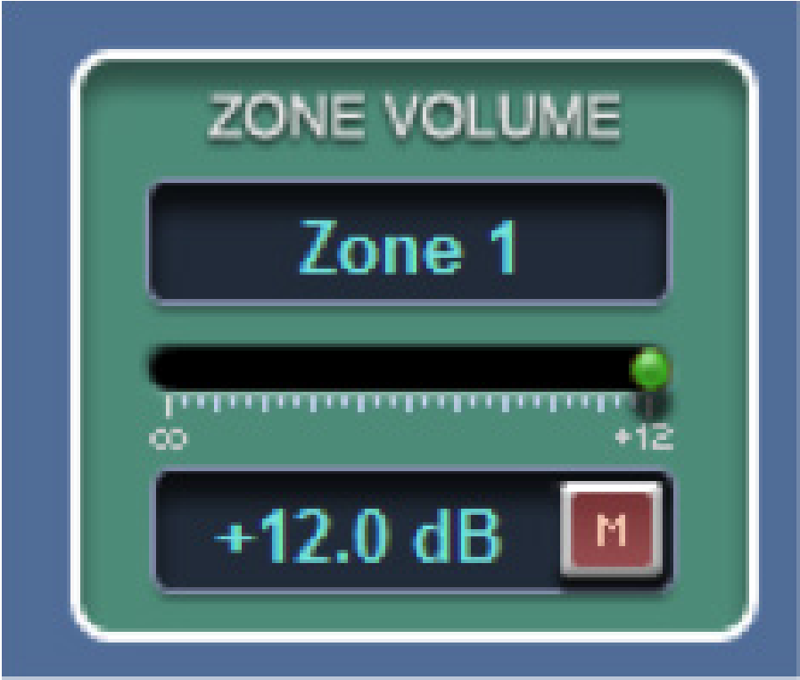
Zone Mix 761 zone volume
gain 6
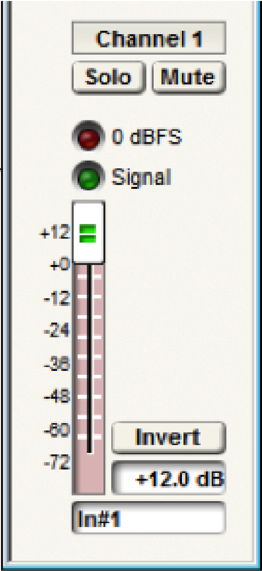
Composer gain module
Step 6:
Go to the analog output section and set the “output level” to +4dBu for balanced connections or
-10dBV for unbalanced connections based upon the input type of the downstream device. These downstream devices vary depending on application but can included hardware such as an amplifier, assisted listening system, or media recorder.
Step 7:
It is almost time to turn on the amp, however, before doing this we want to do one of two things;
1) turn the amp’s input trim to the lowest setting or off
2) if there is no input trim on the amp, use the output gain in the DSP to turn the audio extremely low or completely off.
This will prevent the speakers from being damaged with audio, which is at its loudest setting due to the end user gain control being set to +12dB, from suddenly playing when the amp is turn on.
Step 8: (amp does not have an input trim)
Turn on the amp and using the output gain fader, turn up the system until the audio is audibly the loudest it should ever be.
Step 8: (amp has an input trim)
First, optimize the DSP output by adjusting the output gain fader if needed, similar to how the input was tuned in Step 4. In other words, turn the output gain up so that the audio is as loud as possible on the meters without clipping, such that the RMS level of the audio resides in the amber. If the output meter indicates clipping, use the output gain to attenuate the level down until the audio stops clipping. Finally, turn on the amp and using the amp’s input trim, turn up the input trim until the audio is audibly the loudest it should ever be.
Step 9:
Now return to the end user gain control in the middle processing and adjust it to the appropriate level for the current conditions. If the above 9 steps were followed, the system should have the maximum dynamic range between the program audio and the noise floor, not to mention that even without audio playing the noise floor should be inaudible. Additionally, the customer can be given access to the end user gain control without the possibility that the gain can be turned up any louder than the loudest setting that was determined in Step 8. This means the customer cannot accidentally damage the system by turning it up too loud.