


-
Type
- Dante
- Networking
- Control
-
System Management
- Composer Management Software
- SymVue Screen Authoring
- AV-Ops Center Remote Monitoring
- ARC-WEB Control Interface Signal Processing
- D100 AVoIP DSP Server
- Radius NX AVoIP DSP
- Prism AVoIP DSP
- Edge AVoIP DSP
- DSP I/O Expansion Cards
- Jupiter DSP
- Zone Mix 761 DSP I/O Connectivity
- xIO Bluetooth Endpoints
- xIO XLR Endpoints
- xIO AVoIP DSP Audio Expanders Control Systems
- T-Series Touchscreen Controllers
- W-Series Controllers
- Control Server
- xControl GPIO Expander
- ARC-Series Controllers
Crestron Symetrix Dialer Example in Composer
Product:Composer Management Software
Manufacturer: Crestron
Type: Control
Introduction
This tech-tip describes how to control a Symetrix Radius NX and telephony interface using a Crestron Pro2-style controller. A complete Symetrix Radius configuration file, the Crestron Simpl application file and custom module for dialing the telephony interface, and the Crestron Vision Tools Pro-e touch screen design for an Apple iPad are included and described. Although this example uses network (UDP) control, it can be modified to support serial (RS¬232) control.
This example supports the standard telephony features of dialing, do not disturb, onhook/offhook, redial, and mute control. In addition the telephone line status is displayed including ready, connected, busy, dialing, fault, and ringing. Features not supported in this example are storing or using speed dials, receiving caller id information, audio volume control, and audio meter information.
While this tech-tip is based on the Crestron Pro2 controller and uses the Crestron iPad application as the touch controller, it can be easily customized to support other Crestron controllers and touch screens including the Crestron XPanel PC application generator.
This tech-tip assumes the programmer is familiar with how to use Composer and has some Crestron Control programming experience controlling other products.
Getting Started
This tech tip starts with an overview of the Composer programming for the Radius AEC, continues with the Crestron Simpl program and customer dialer module, and finishes with the touch screen design.
Composer
The first step is to create the Composer site file for your conferencing application. The included file, v1.2 Simple ATI Card Demo.symx, is a working example of a single line analog telephony audio conferencing project with a single Radius AEC and analog telephony interface (ATI) card.
To aid in understanding how to control the ATI, this application focuses on the core telephony functions to create a fully functional dialer with output mute control. This application does not use speed dial functions, and does not control ancillary tone gains.
This Crestron dialer application works by translating key presses on the Crestron touch screen interface to Symetrix API commands and takes the Symetrix command acknowledgments and updates the touch screen as necessary.
Controller Numbers
In order for this Crestron control application to work, the Composer site file must have controller assignments defined for the telephony features as shown in the following figure. In this figure notice that the controller numbers have been assigned to the ATI user interface and range from 121 for the DTMF digit 1 to 145 for the fault indicator. While in your site file these controller numbers can be different from the ones predefined in the demo site file, it is very important that the controller number assignments used in the Composer file match the controller numbers that the Crestron controller will be using. More on this later when the Crestron Simpl program is introduced.
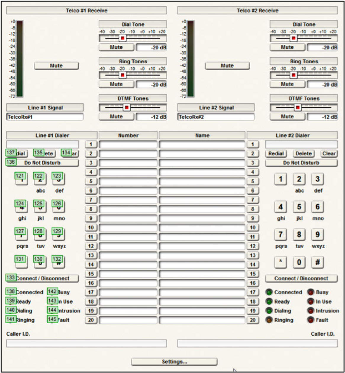
Figure 1. The Composer settings for the Analog Telephony Interface.
In addition, this project has control number 155 assigned to the mute button of the Telephony Output #1 as shown in the following figure. While this controller assignment can be any value between 1 and 10000, it is important that it match the controller number used by the Crestron Simpl module.
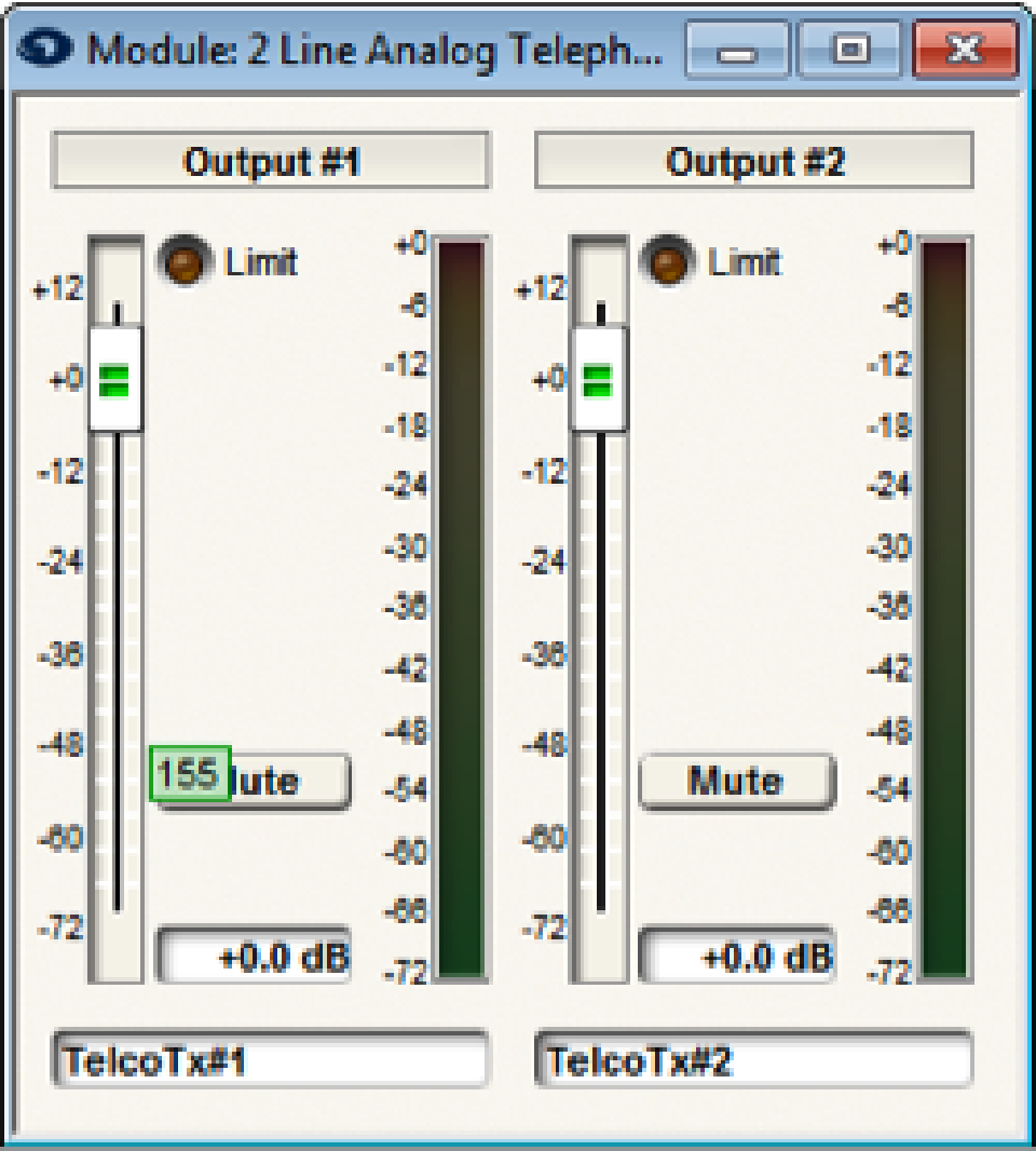
Figure 2. The telephony output signal mute controller.
Quiet Mode
For this demo application, it does not matter whether quiet mode is enabled or not. Symetrix recommends leaving quiet mode in the on state (factory default setting). Turning quiet mode off is only required when there are string commands to be interpreted (speed dial names and digits, and caller id information). In this example, only button pushes, and their respective acknowledgments, are used by the Crestron controller. In more advanced dialing applications that utilize speed dials, retrieve the last digits to have been dialed, or receive caller ID information, quiet mode will need to be disabled to support parsing detailed string acknowledgements returned by the Symetrix processor.
Push Enabling
Once the controller numbers have been defined, it is necessary to ensure the controller numbers in the following table are set to ‘Push’ so that changes in the state of the Symetrix device are automatically sent to the Crestron control system.
To enable Push, within Composer navigate to Tools-> Remote Control Manager,
and select each of the parameters in the following table and select Enable Push.
| Controller | Control Number |
| Connect / Disconnect #1 Button | 133 |
| Line #1 Do Not Disturb | 136 |
| Line #1 Connected LED | 138 |
| Line #1 Ready LED | 139 |
| Line #1 Dialing LED | 140 |
| Line #1 Ringing LED | 141 |
| Line #1 Busy LED | 142 |
| Line #1 In Use LED | 143 |
| Line #1 Intrusion LED | 144 |
| Line #1 Fault LED | 145 |
| Output 1 Mute Button | 155 |
Table 1. The controller number assignments that need to be set to Push Enable.
The resulting settings should match the following figure.
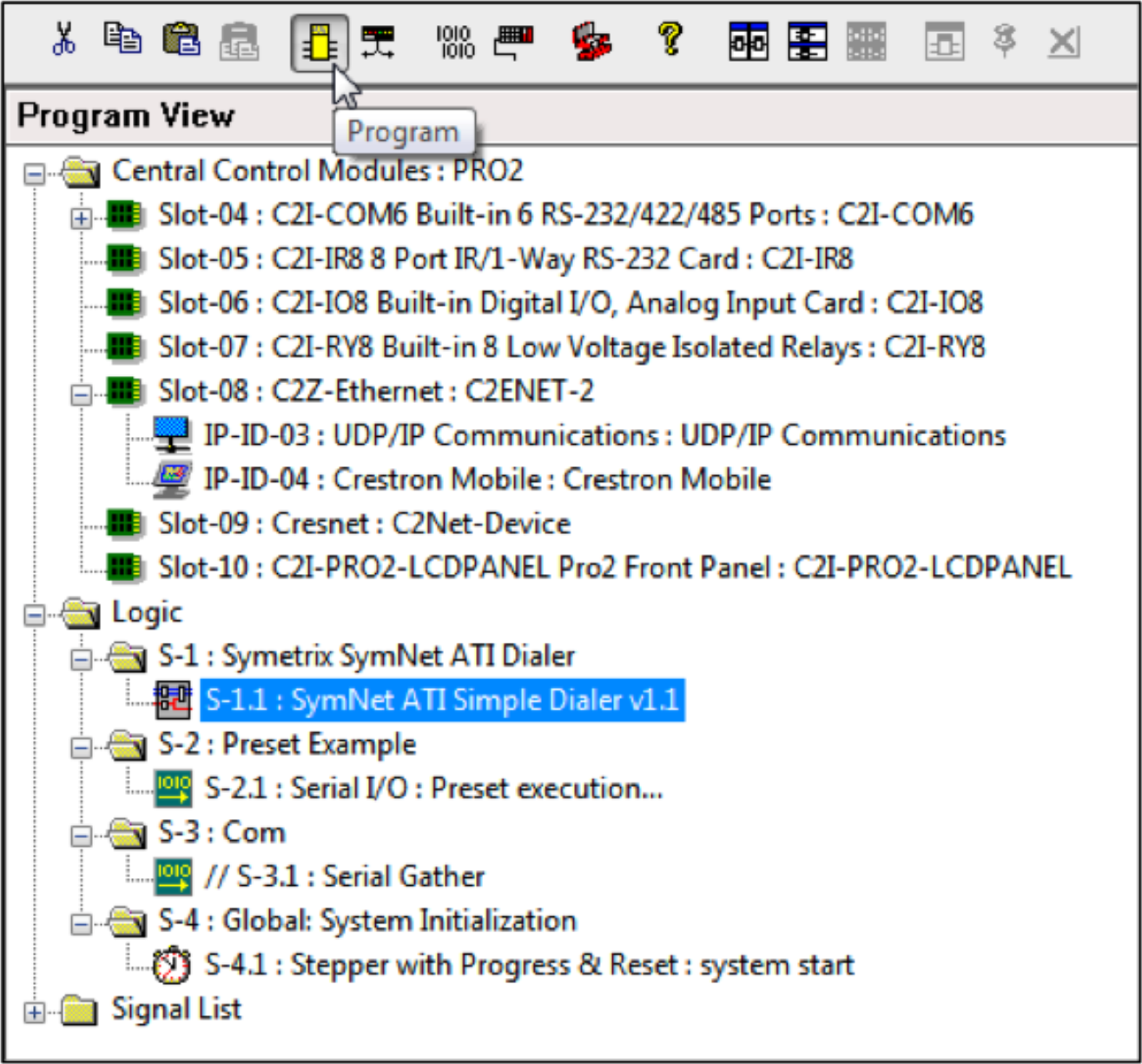
Figure 3. Enabling push for the Symetrix controller parameters.
Once the Composer project is ready, push it to the Symetrix processor and then start with the Crestron Simpl programming outlined below.
Push Interval
The default value of the push interval (100msec) is recommended to ensure timely feedback as the state of the Symetrix processor changes. Changes to the push interval can be made using the PUI API command.
Note:
- This project supports the standard telephony functions including an output mute.
- The controller numbers used in the Composer project must match those used in the Crestron Simpl project.
- Enable push for the Symetrix controller numbers
- This system is compatible with quiet mode (factory default setting) on
Crestron Simpl Project
The example project is designed for a Crestron Pro2 controller using Simpl v4.0.2.20. If using a different Crestron control processor, click the Configure icon in Simpl, select the correct Crestron controller and drag it into the design. Be sure to add UDP communications and the touch screen of choice when
changing control processors to something other than what is used in the demo configuration.
Once completed the configure screen should look similar to the following figure.
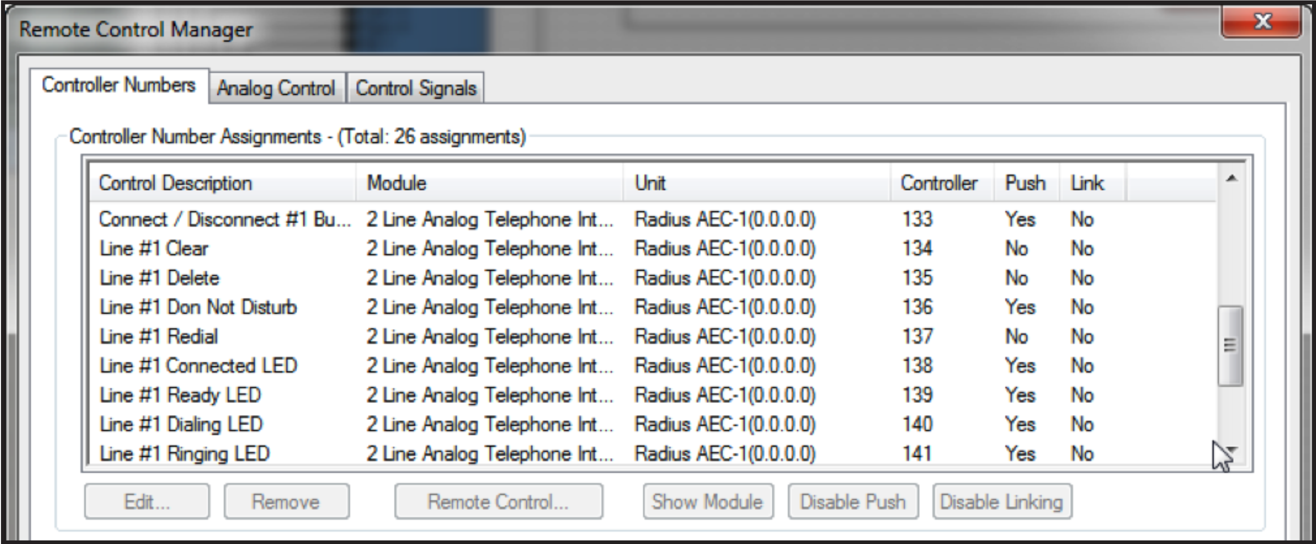
Figure 4. The Crestron control system configure screen.
Next, set the IP address of the Radius AEC that Crestron will be controlling by double clicking on the UPD/IP communication block and selecting IP Net Address. In this example, the Radius AEC has the IP address of 192.168.100.105.
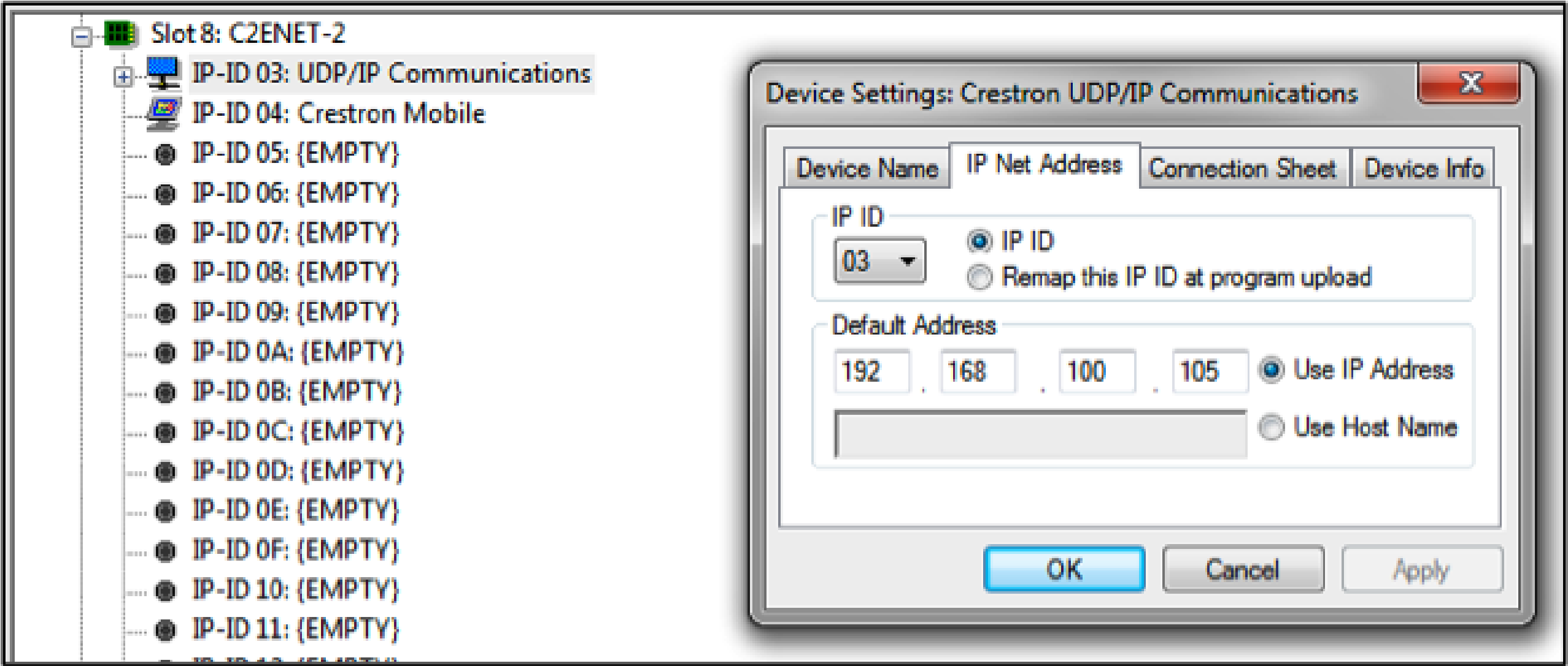
Figure 5. Configuring the IP address for the Symetrix device to be controlled.
When using a control system to control the Radius AEC, it is recommended that the Radius AEC have a static IP address to ensure the control system can always communicate with the device regardless of DHCP server status.
In this example there is also a Crestron Mobile device that is the control module for the Apple iPad controller configured using Crestron’s Vision Tools Pro-e software. Other touch panel devices could also be used. Using an Apple iPad with Vision Tools Pro-e requires installing on the target iPad the Crestron iPad application (currently $99) from the Apple ITunes store. Although the price seems high for this application, it makes the iPad an inexpensive touch screen for the Crestron processor. In the Program mode of Simpl (pressing the Program button on the menu), the Simpl file will look like the figure below.
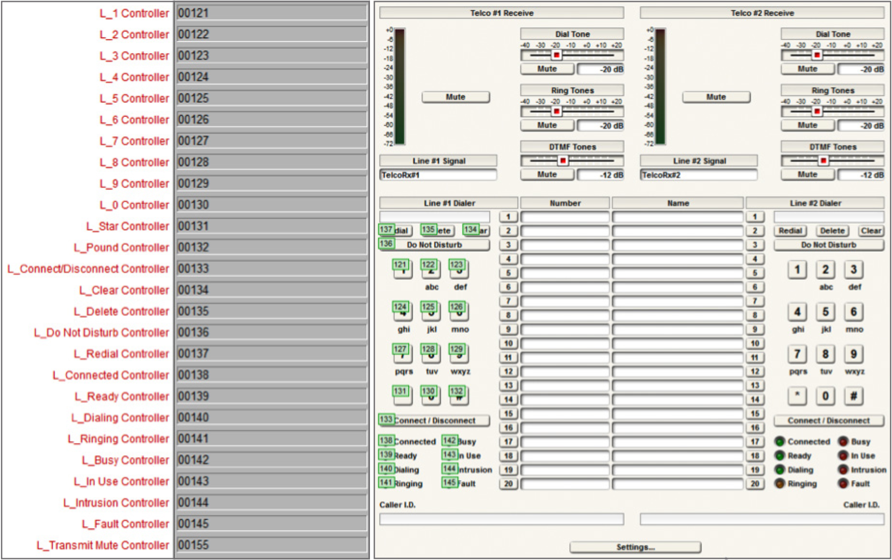
Figure 6. The Crestron control example code.
The main parts of the program are:
- The SymNet ATI Simple Dialer v1.1 is the custom user module described in this tech-tip to control the Radius AEC and ATI card.
- The Preset example shows how a preset may be executed. This code is not used in this application.
- The Com section is there for applications where serial (RS-232) communication is used instead of network (UDP) Control. This section is commented out in the current project. When using serial control instead of network control, it is necessary to configure the serial porton the “Configure” screen in Simpl and uncomment this Com section. Network (UDP) control is recommended.
- The Global System Initialization section is used to start the program.
Simple-Telco-Example.smw
While the simple dialer module supports one phone line, it would be possible to have two of these modules in the Crestron Simpl program to control both analog telephony interfaces on an ATI card. The second phone line would require unique controller numbers and be configured as the single phone line was described previously. The input and output signals of the dialer module are shown in the figure below. The input signals (L1_1_press, etc.) originate from button presses from the Crestron Mobile symbol.
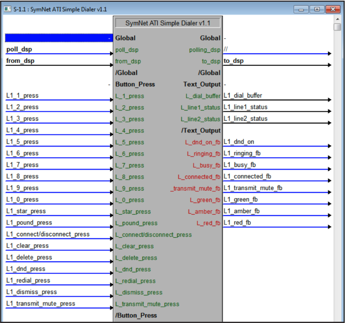
Figure 7. The inputs and outputs of the SymNet ATI Simple Dialer module.
The input and output signals are defined in the following table.
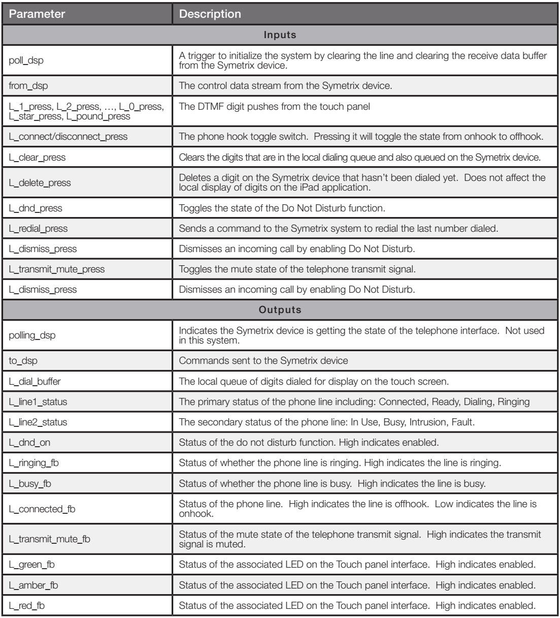
Table 2. The description of the input and output parameters of the ATI Simple Dialer module.
In addition to the parameters defined, there are the arguments that are passed into the dialing module that define the control numbers used by the Crestron program. The arguments are the same control numbers assigned in the Composer site file as shown in the following figure.
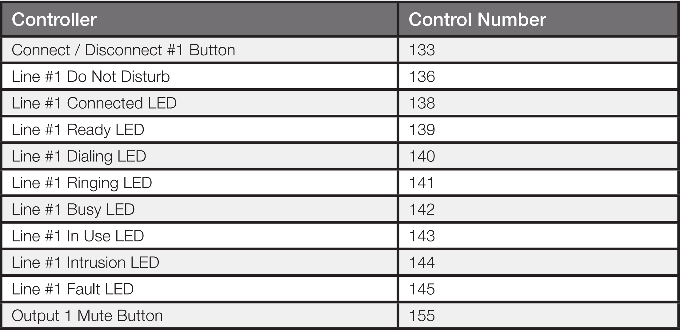
Figure 8. Control numbers for the Simple ATI dialer module (left) and assigned in the Composer project (right). These numbers must match!
The controller numbers should be entered with leading 0’s as shown because the controller numbers will be used to form the API commands that are sent to the Symetrix device and also are used match against the acknowledgments received for the controllers that have values “pushed” back to the control system.
ATI Simple Dialer v1.1 User Module
The ATI Simple Dialer module is defined in the file SymNet ATI Simple Dialer v1.1.umc and appears as shown in the following figure.
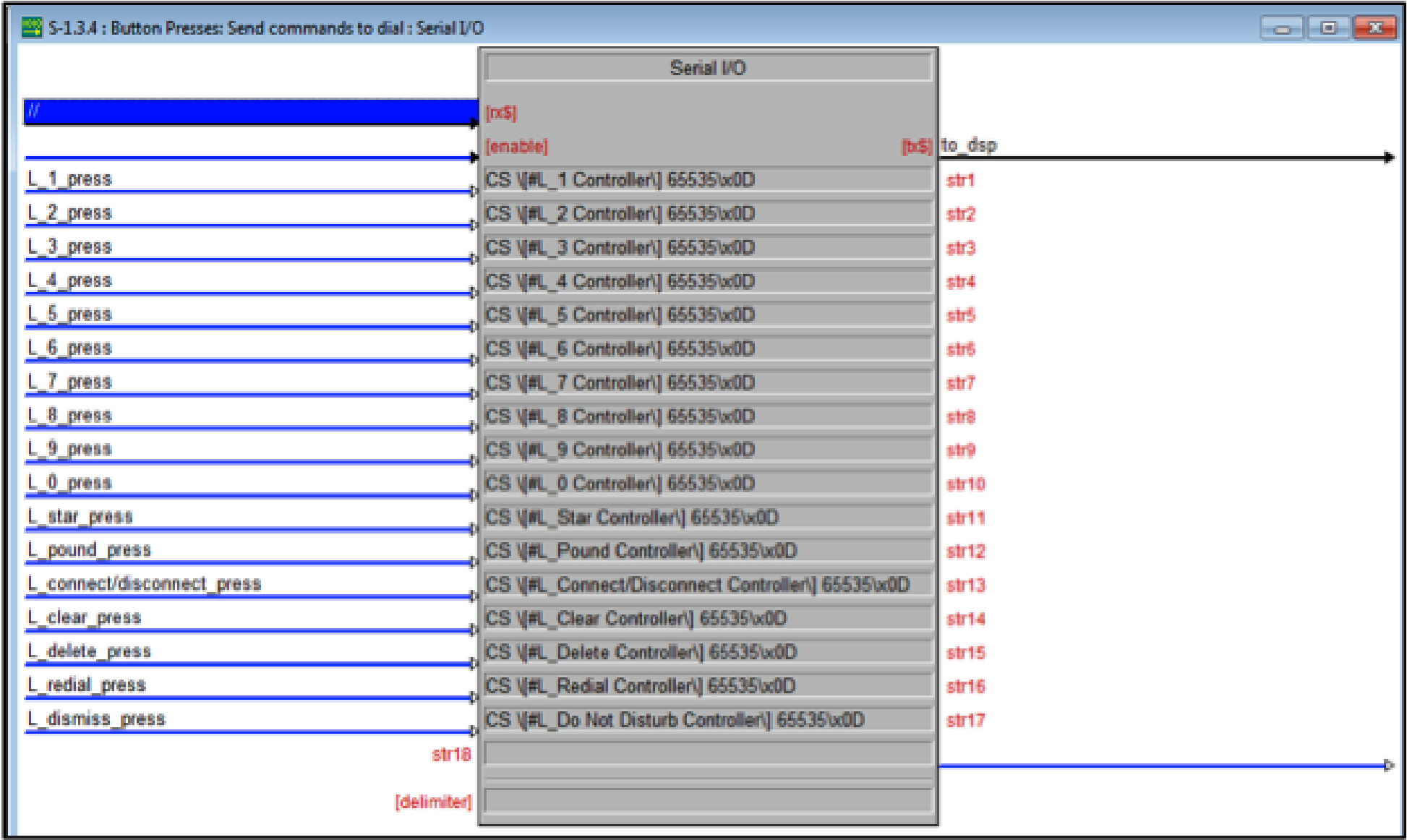
Figure 9. The inside of the Simple Dialer user module.
This module does the work of receiving the control signals and arguments and translating those signals into commands that are sent to the Symetrix device. In addition as acknowledgments are returned from the Symetrix processor, this module updates the user interface to ensure it reflects the state of the Symetrix processor.
To simplify keeping track of the digits that have been dialed, a queue of characters is created locally to store and then send the digits to the touch screen. The digits to be dialed are dialed individually as they are pressed on the touch screen.
The code for the button presses sends the appropriate commands using the assigned controller numbers to the Symetrix device. For example, pressing the 1 key on the touch screen will cause the L_1_press key to go high which in turn will send the command CS 00121 65535\x0D to the Symetrix processor where 00121 is the controller number assignment for the digit 1 that was supplied as an argument to the module. All commands are terminated with a carriage return, hence the \x0D after the command.
Figure 10. The commands that are sent to the Symetrix device.
The acknowledgements from the Symetrix device are monitored to determine the line status and whether the phone is ringing, etc. For example, if the control system receives the acknowledgment: #00141=65535
Then, as shown in the following figure, the Crestron code will parse that information and set the signal L_ringing_on to high to indicate the phone is ringing. This signal is processed and then user interface elements are updated and sent to the touch panel to inform the user that the phone is ringing. Once the line has been answered by sending the command: CS 00133 65535\0xD the Symetrix device will send the pushed acknowledgement: #00138=65535 to indicate the line is connected.
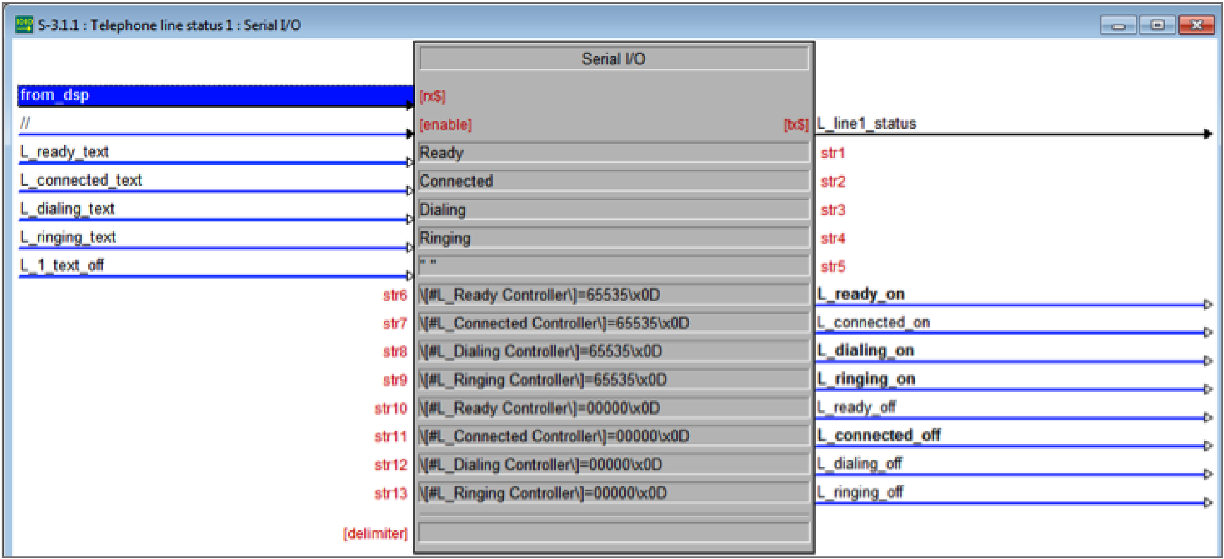
Figure 11. Parsing the acknowledgements is performed by matching particular strings within the data received from the Symetrix device.
The transmit mute state and the do not disturb buttons track their respective state from the Symetrix device. Changes to the mute or do not disturb buttons through some other way will be properly reflected in the user interface.
Note:
- The sample Crestron file and module are designed for one phone line.
- Set a static IP address of the Symetrix device to be controlled so the control system can always find the device.
- Set the IP address of the Symetrix device to be controlled in the UDP control settings.
Touch Screen Design
The Touch screen design was created in Visual Tools Pro-e v5.3.19. This example has two main screens – the dialer screen and the incoming call screen.
The controller numbers on the Crestron Touch Panel GUI match the control numbers on the Crestron Mobile controller in the Simpl program as shown in the following figure. For example the digit 1 on the touch screen has a controller number of 161 which becomes the L1_1_press control signal on the
signal press_161 which in turn is sent to the SymNet Simple ATI Dialer user module to indicate that the digit 1 has been pressed which in turn sends and API command to the Symetrix device to dial the digit 1.
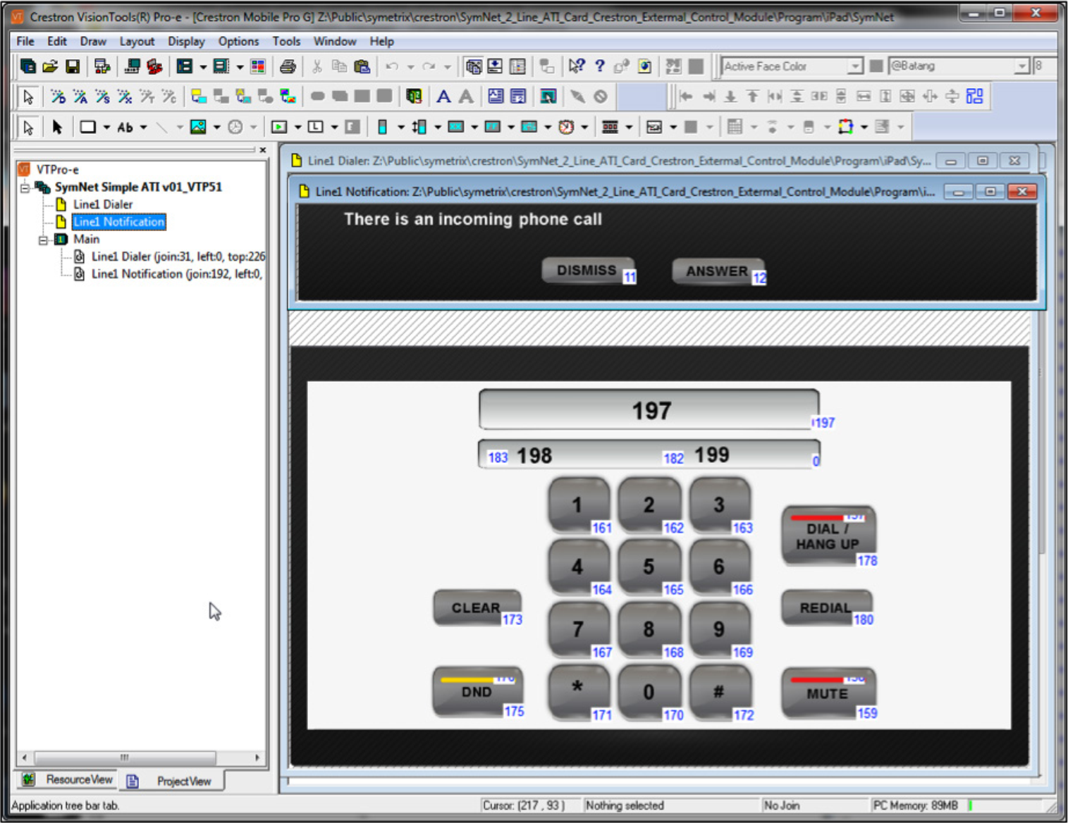
Figure 13. The Crestron Mobile touch screen interface with the corresponding control signals to the Touch Panel design
Compile and upload this program and send it to the IP address of the iPad. See the next section for finding the IP address of the iPad.
Using the Crestron iPad application
Once the Crestron iPad application has been downloaded, launch the application on the iPad. As an alternative to using the Crestron iPad application, both the Vision Tools Pro-e project and the Crestron Simpl application can be modified to support XPanel or other Crestron touch panels.
Before configuring the iPad, note the IP address shown on the bottom of the iPad display as shown in the following figure. This is the address that the Vision Tools Pro-e touch panel design program use for upload of the user interface
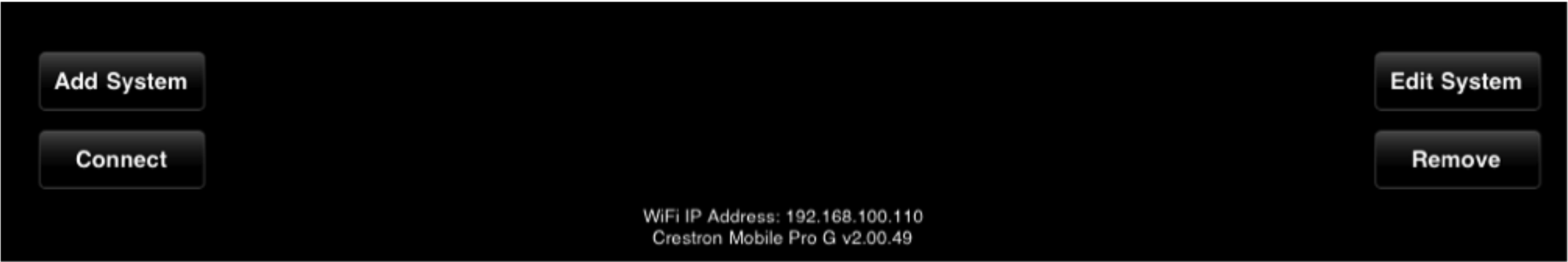
Figure 14. iPad IP address at the bottom of the iPad display.
To configure the system, select Add System and enter the fields as shown in the following figure. Select Yes for Use Local File. By default the system will use Port 41790 for Part A and 41791 for Port B. While no password is required by default, a password must be entered. In this example, enter any password. Press save when done.
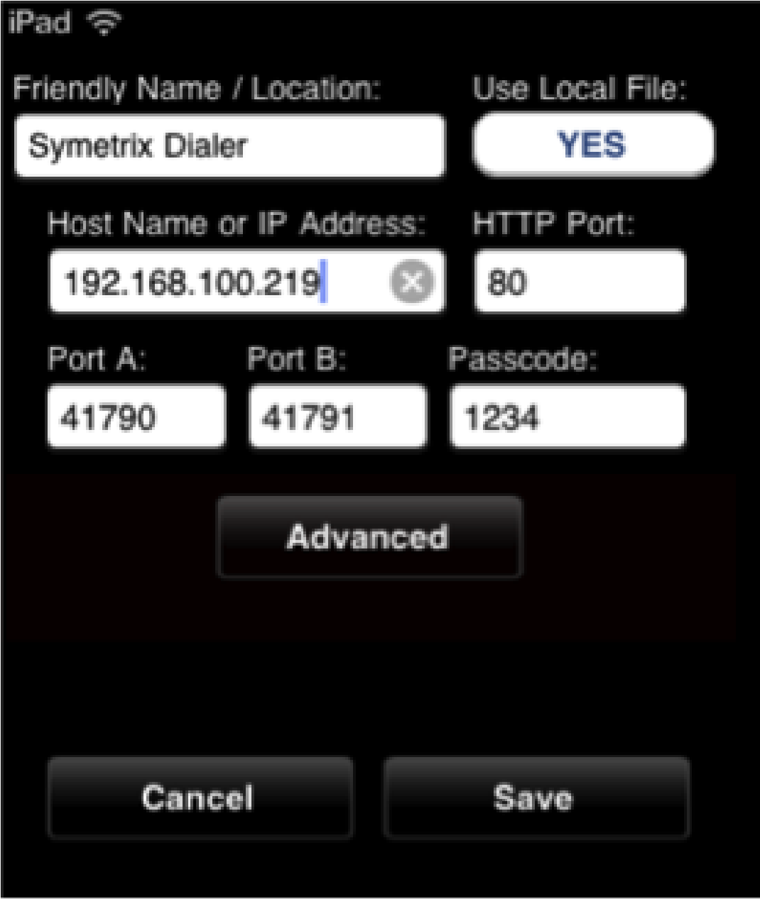
Figure 15. The configuration screen on the Crestron iPad application.
Next select the name of the system just created and press Connect. This should launch a screen like the figure below.
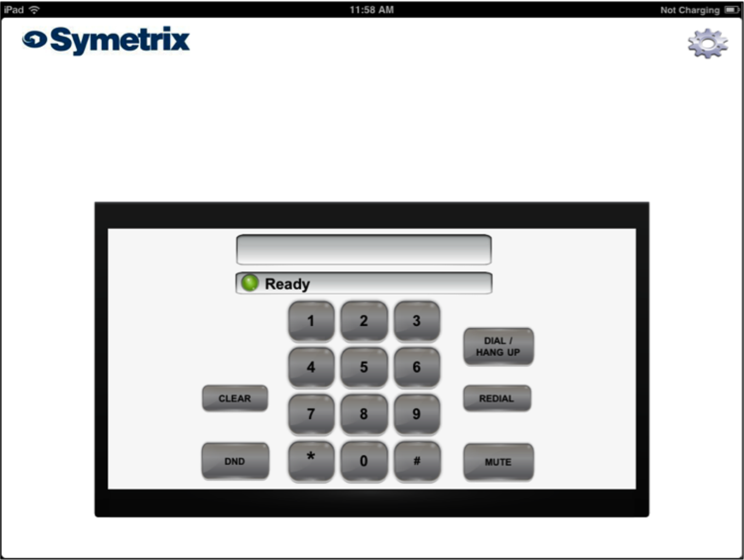
Figure 16. The main user interface of the Crestron iPad application.
When there is an incoming call, the Answer call window appears as shown in the following figure.
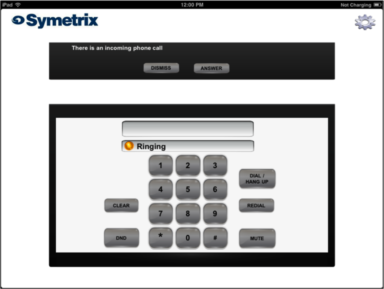
Figure 17. The user interface when there is an incoming telephone call.
To get to the configure screen again within the iPad application, press the gear wheel in the upper right hand corner. While not necessary, to re-initialize the Symetrix Crestron Program, press the Symetrix logo which will set the poll_dsp signal high and cause the ATI dialer to re-query the state of the line, do not
disturb, and transmit mute settings.
Note:
- Download the Crestron app for the Apple iPad (the $99 only hurts for a couple of minutes)
- Configure the iPad for “Use Local file”
- Upload the touch panel files to the Apple iPad
Troubleshooting
If the iPad touch screen does not seem to be working to control the Symetrix device then,
- Check that the IP address of the Symetrix device was entered properly into the UDP control screen in Crestron’s Simpl configuration screen.
- Check that the IP address of the Symetrix device hasn’t changed via the front panel LCD display. Remember to use a Static IP address for the Symetrix device.
- Check that the controller numbers entered into the ATI dialer module match the controller numbers defined in the Symetrix configuration file.