


-
Type
- Dante
- Networking
- Control
-
System Management
- Composer Management Software
- SymVue Screen Authoring
- AV-Ops Center Remote Monitoring
- ARC-WEB Control Interface Signal Processing
- D100 AVoIP DSP Server
- Radius NX AVoIP DSP
- Prism AVoIP DSP
- Edge AVoIP DSP
- DSP I/O Expansion Cards
- Jupiter DSP
- Zone Mix 761 DSP I/O Connectivity
- xIO Bluetooth Endpoints
- xIO XLR Endpoints
- xIO AVoIP DSP Audio Expanders Control Systems
- T-Series Touchscreen Controllers
- W-Series Controllers
- Control Server
- xControl GPIO Expander
- ARC-Series Controllers
Input Logic Modules in Composer
Product:Composer Management Software
Type: Control
This tech tip will cover a variety of ways in which the “Input Logic Module” from
Control Modules->Control Logics can be used within a Composer system. Input Logic Modules are typically driven by External Control Inputs. As such the following section will cover the basics of Control Input modules.
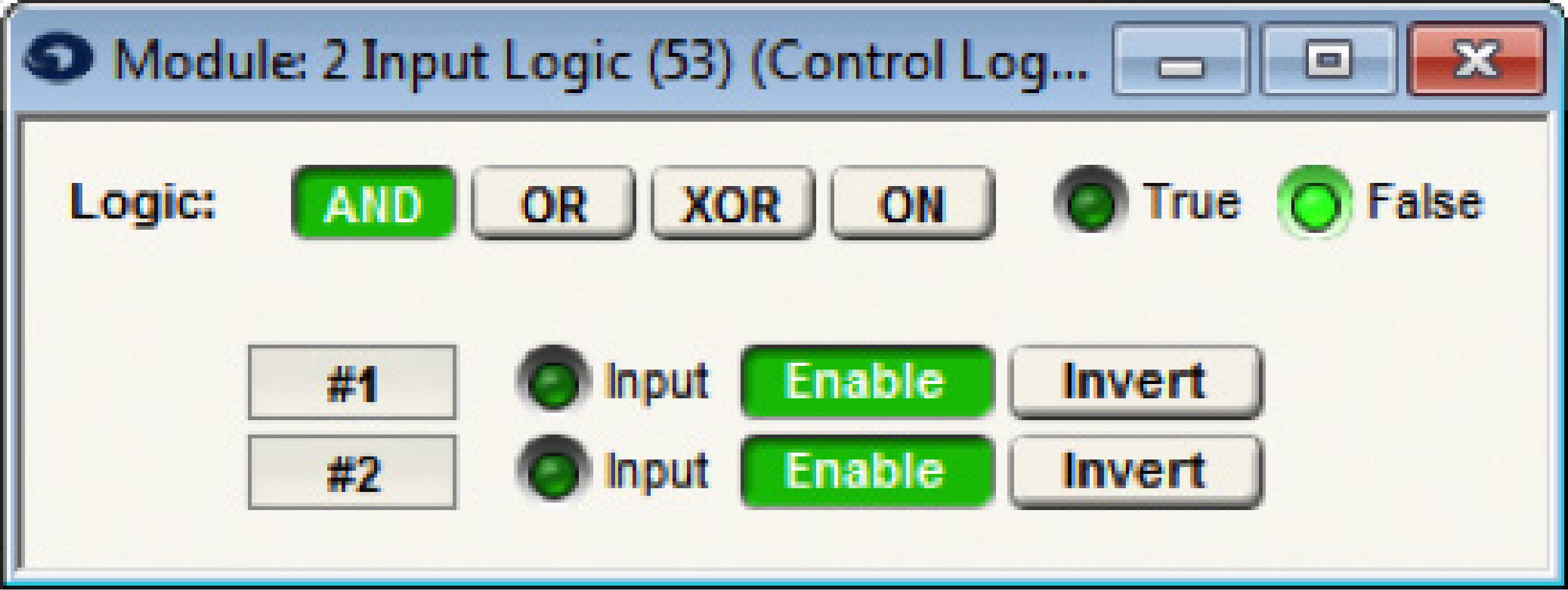
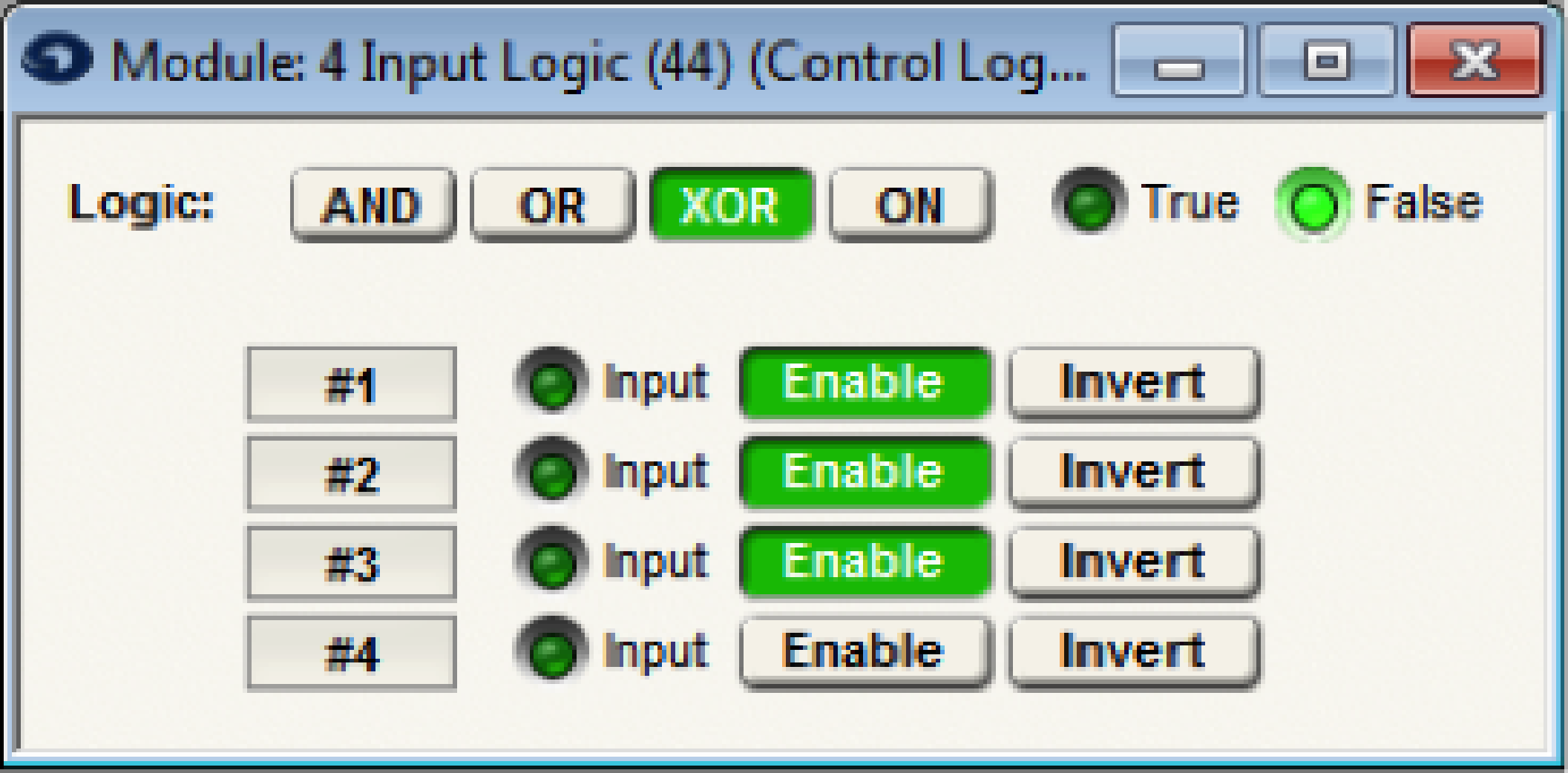
Input Logic Modules:
The modules have two outputs labeled, True and False. The True output will be 100% when the logic function is True. The False output is always the complement of the True output (negative logic). Any input less than 50% is assumed to be 0, or false. Any input greater than or equal to 50% is assumed to be (1), or True. For each input, there is an enable button. When turned on, the corresponding input will affect the output. When turned off, the input will be ignored.
The Input Logic modules can perform one of (4) different logical operations: And, Or, Xor and On. The And function is True only if all enabled inputs are True. The Or function is True if any one of the enabled inputs is True. The Xor function is True if any odd number (1, 3, 5) of enabled inputs are True. Note: If all inputs are disabled, the Xor and Or functions will be false and And function will be True. The On function is always true regardless of the state of the inputs. (On may be useful to generate a constant 100% control signal). By using the False output, you can create the inverse function, i.e. Nand, Nor, XNor, or Off. Truth tables are show below for the 2- and 4- input versions to illustrate this.
The tables for the large input versions will follow the same logic as shown below.
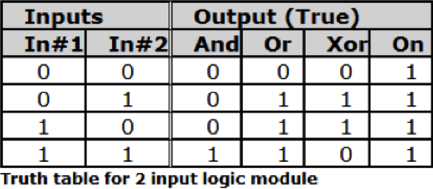
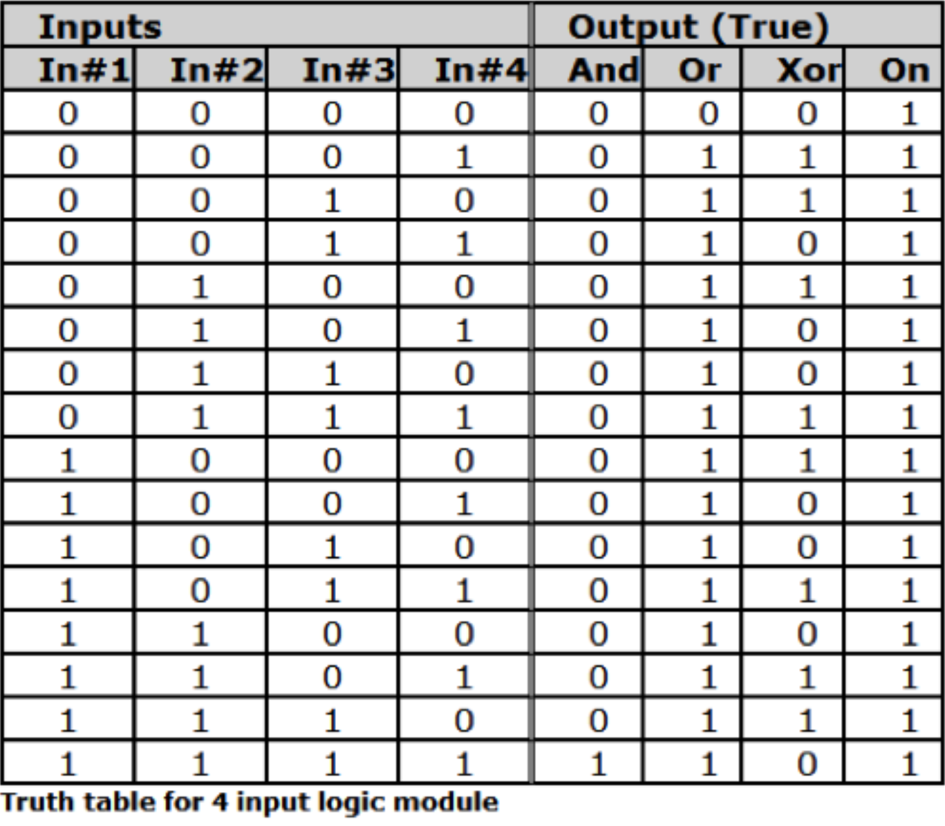
Note: 0 = false or 0%, 1 = True or 100%. If the False output is used substitute 0 for 1 and vice versa for all outputs. The tables assume all inputs are enabled.
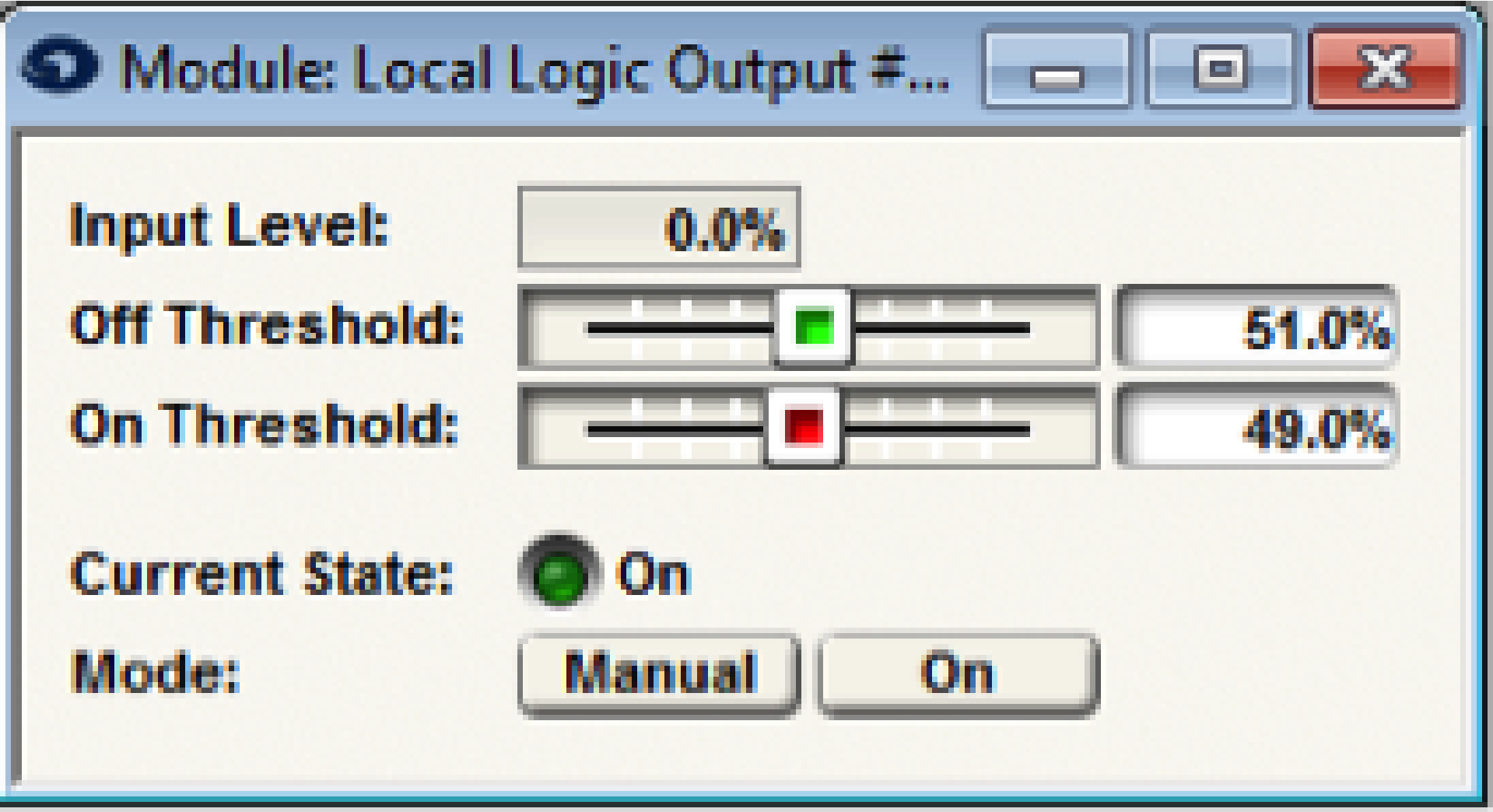
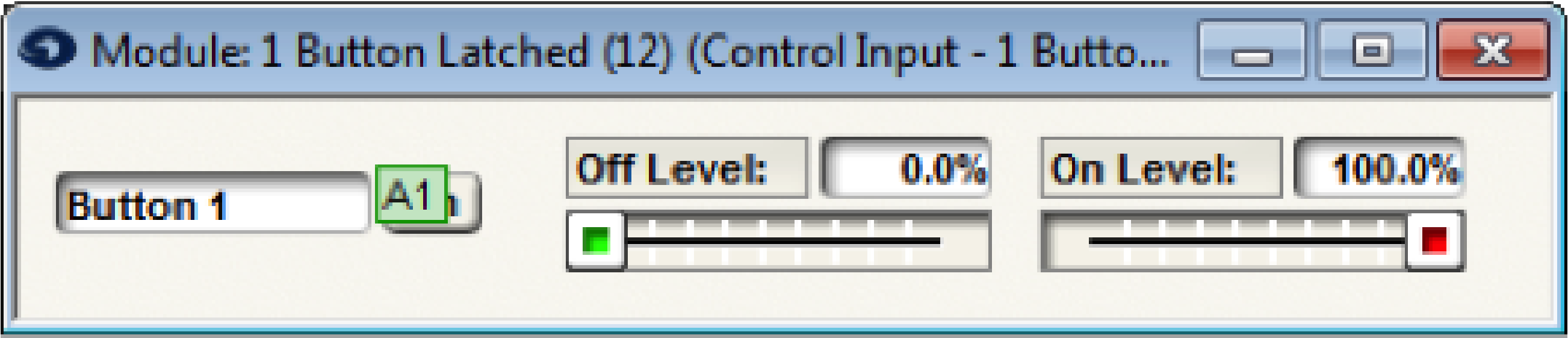
Controls:
- Off Level. Sets the control signal level that will be output when the button is off (0-100%). Adjust using the slider or click in the text entry box to specify a numerical value. Typically this valve would be 0%.
- On Level. Sets the control signal level that will be output when the button is on (0-100%). Adjust using the slider or click in the text entry box to specify a numerical value. Typically this value would be 100%.
Note: to make the button act in reverse, set the off level to a value higher than the on level. - On. Manually controls the button state. You can assign this to an external controller to provide an interface from an external controller to a control signal.
A space is provided to name each button. Click in the box adjacent to the On button and enter a name. The name entered will also appear on the modules output label(s).
Note: A button module can also be used to interface to an external on/off type controller (analog input
or RS-232/485). This allows processing and using an analog control or RS-232/485 controller as a
control signal. Assign the On button to an external controller. Then the module output will reflect the
state of the external controller and can be routed, processed, and connected as a control signal.
Example 1: Using “AND” Logic Operation
In this example, a Room Combine system with 3 rooms is configured such that, when separate, each room’s head table position is on the north side of the room and speaker delay is configured accordingly (Preset 2).

When all three rooms are combined into a single, large partition, the system needs to automatically reconfigure the head table position to the west side of the room and as such, reconfigure the subsequent speaker delays to support this new head table position (Preset 1).
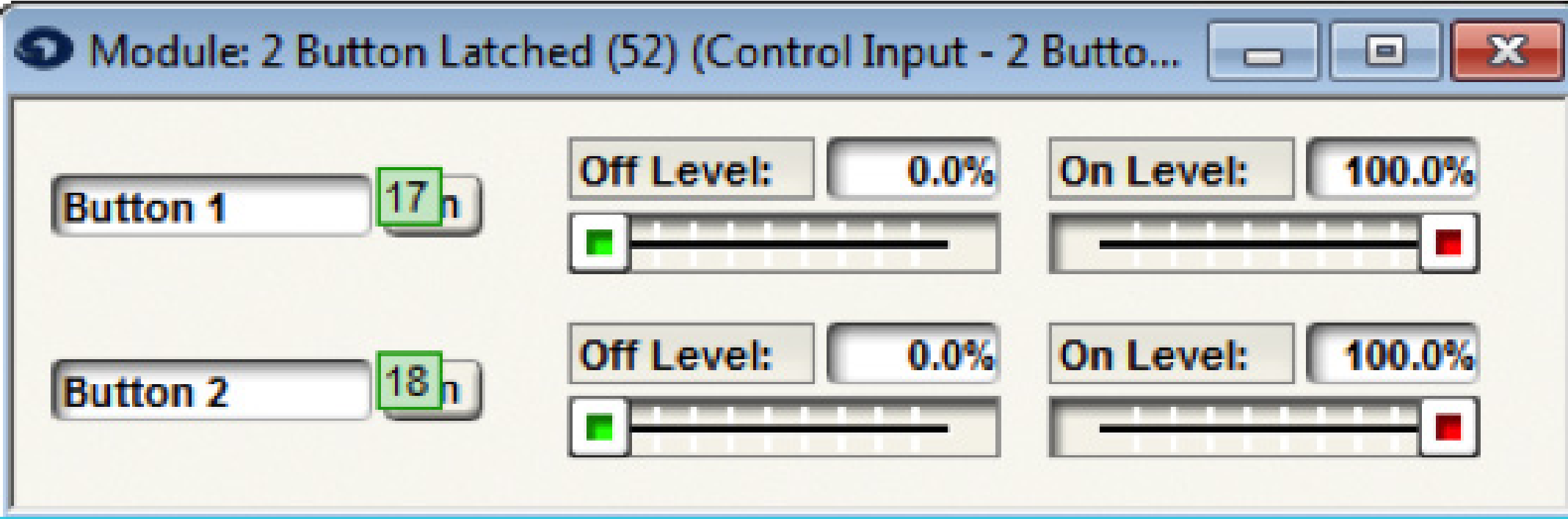
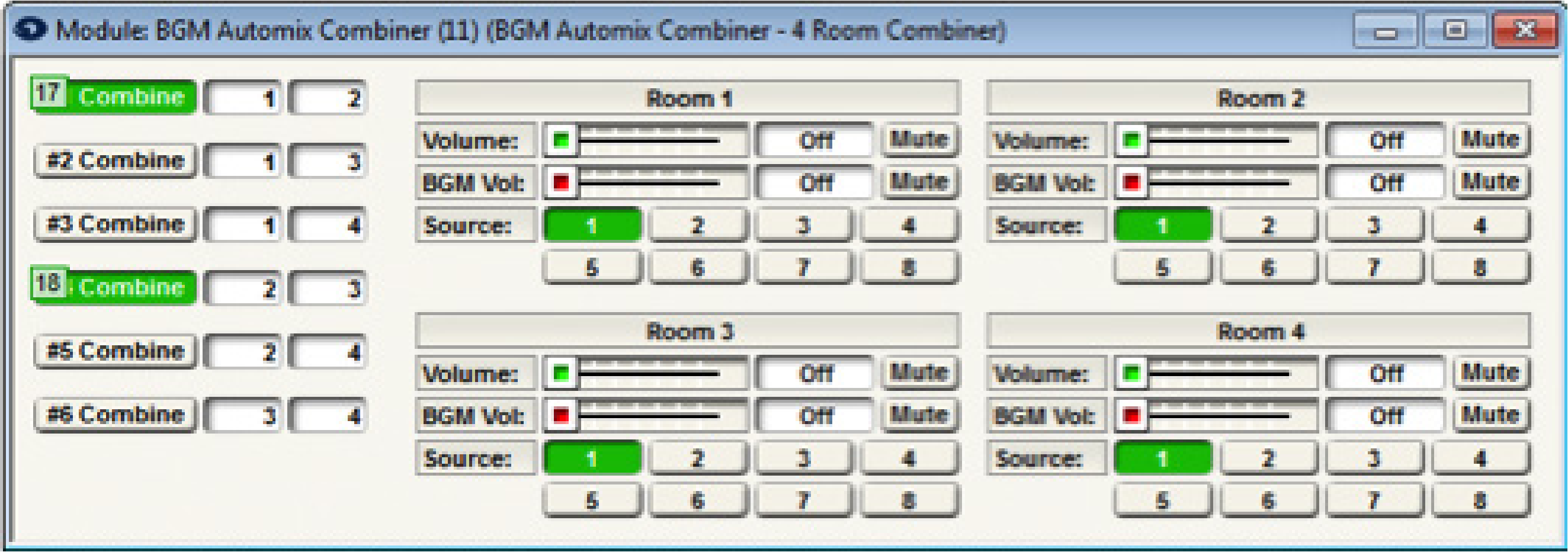
To accomplish this, a 2 Button Latched module is used to mirror the two combine buttons of the room combine module. Notice the control number assignments on the 2 Button Latched Module match the control number assignments of the BGM Automix Combiner, using controllers #17 and #18 respectively. This effectively links the room combiner “Combine” buttons to the 2 button latched “On” buttons.
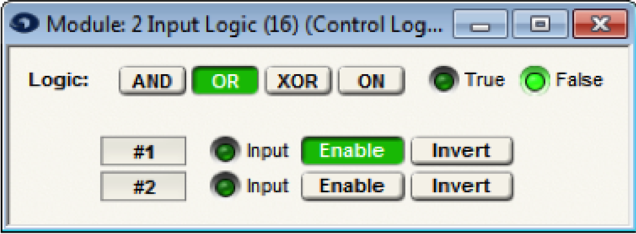
The 2 Input Logic module monitors the status of the 2 Button Latched, which mirrors the Room Combiner “Combine” buttons, and then triggers the appropriate preset based upon the combine status.
When none of the rooms are combined, both inputs of the 2 Input Logic module will be 0%. This means the output of the 2 Input Logic module will be False and Preset 2 will be triggered.
When only one pair of rooms are combined, either 1 & 2, or 2 & 3, the inputs of the 2 Input Logic module will be 0% and 100% respectively. This means the output of the 2 Input Logic module will be False since it is set to ‘AND’ and both inputs must be 100%. As such, Preset 2 will be triggered.
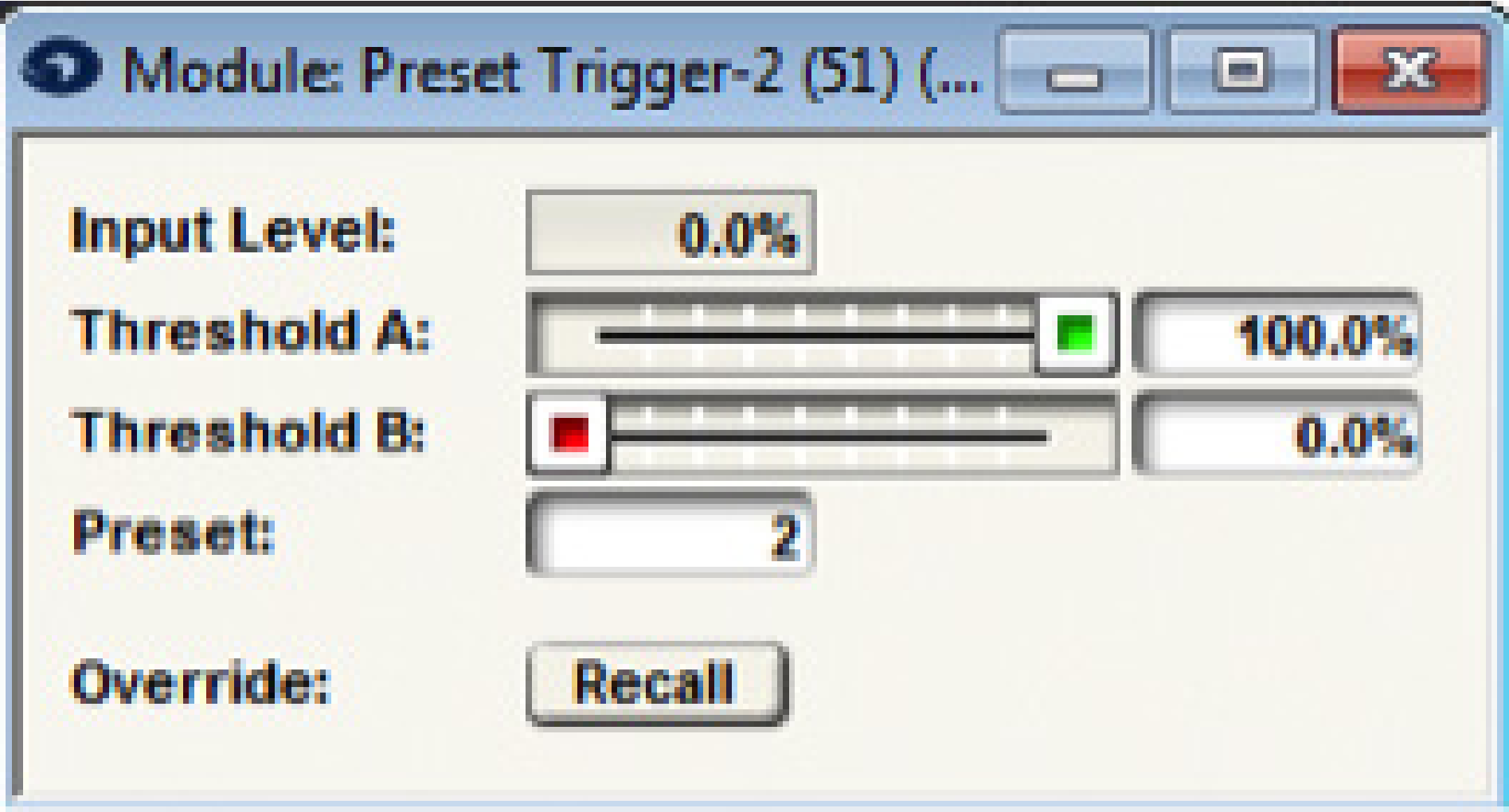
Once all 3 rooms are combined, then both inputs of the 2 Input Logic module will be 100%. Since both are at 100% and the 2 Input Logic module is set to ‘AND’, this means the output of the 2 Input Logic module will be True and Preset 1 will be triggered.
Example 2: Using “OR” Logic Operation
In this example a 2 Input Logic Module set to ‘OR’ provides a Fire Alarm Mute/Unmute all function.
A 1 Button latched feeds a single input of a 2 Input Logic module set to OR.
Preset 1 or Preset 2 will be triggered based upon the output of the 1 Button Latched module.
Typically in an application like this, the 1 Button Latched “On” button will be assigned to an External Control Input that is connected to a fire alarm relay. Once the fire alarm relay is engaged (stays engaged until the relay is reset), the 1 Button Latched “On” button is pressed and will output 100% to the 2 Input Logic module input. The 2 Input Logic module’s output will be True since it is set to OR and Preset 1 will be triggered (i.e. Mute All).
When the fire alarm relay is reset, the 1 Button Latched “On” button will turn off and the output will be 0% to the 2 input Logic module input. The 2 Input Logic module’s output will be False and Preset 2 will be triggered (i.e. Unmute All).
Example 3: Using “XOR” Logic Operation
In this example, a conference room has three modes of operation, where two of the modes require a projector screen to be lowered in the conference room. A 4 Radio-Button Module is used to select the conference room mode and trigger the respective preset that configures the audio inputs accordingly, while a 4 Input Logic module set to XOR is used to control the Local Logic Output that raises and lowers the projector screen.
Note: The Xor function is True if any odd number (1or 3) of enabled inputs are True. If all inputs are disabled the Xor functions will be false.
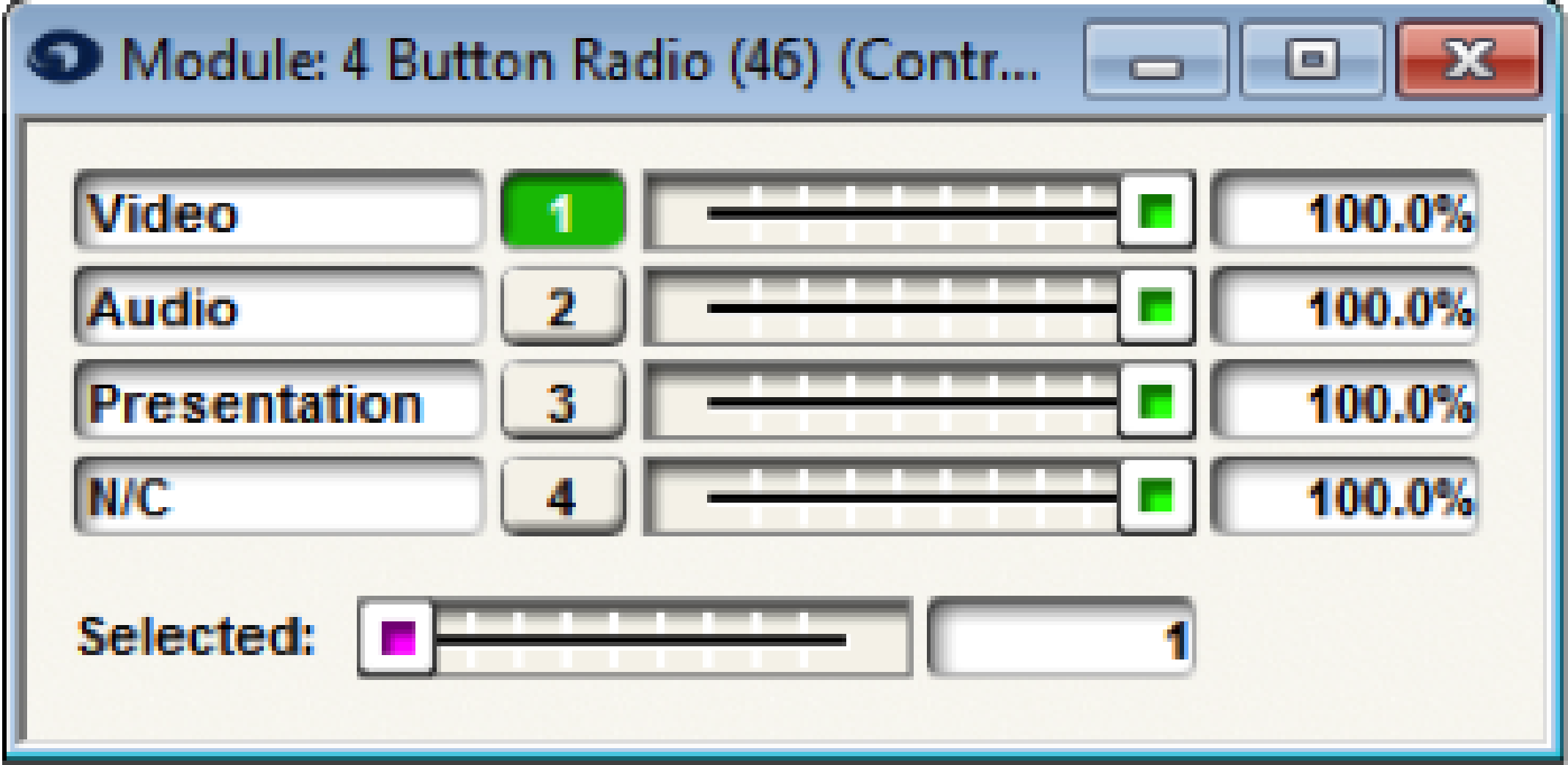
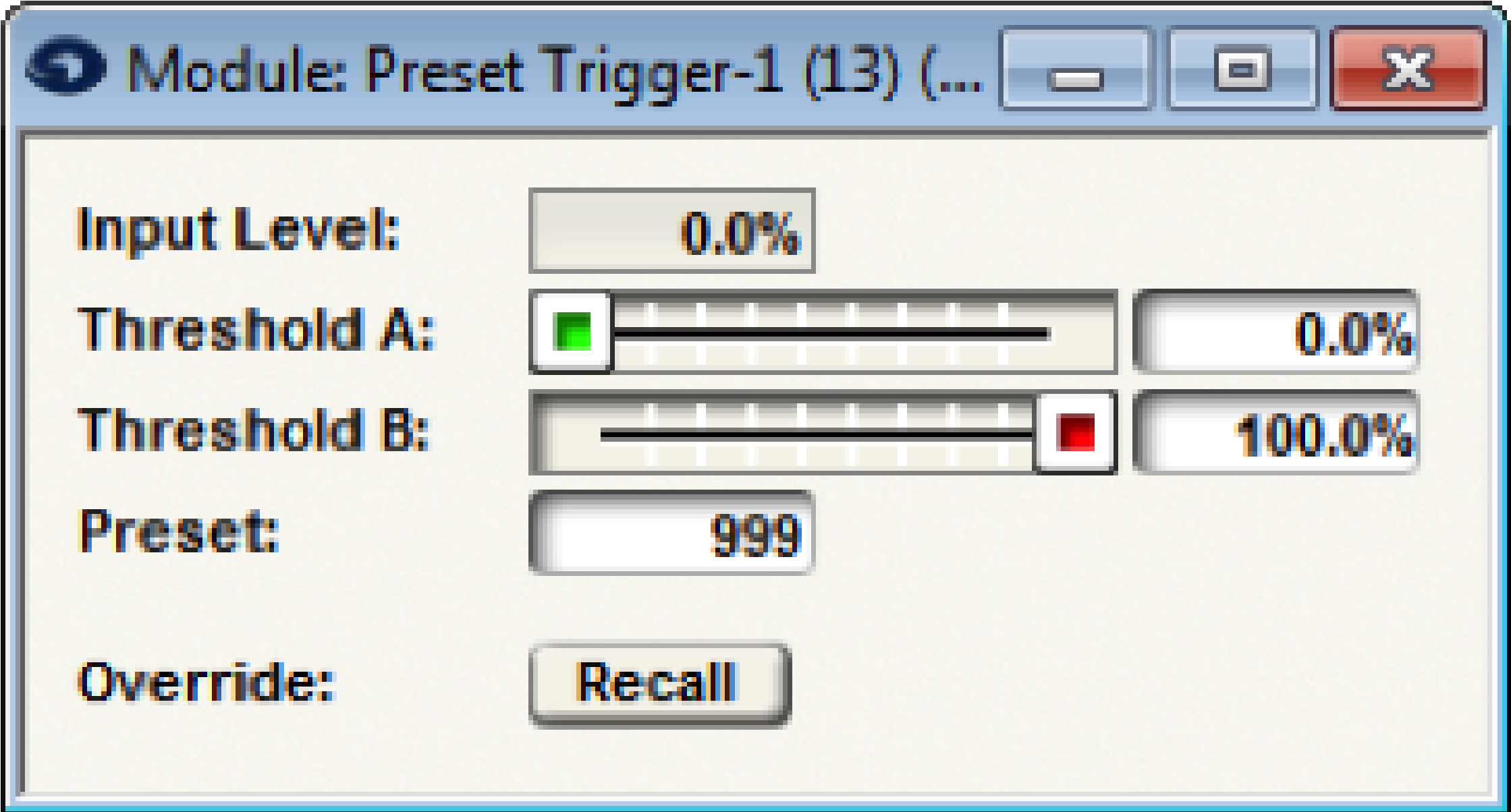
When radio button 1 is selected for Video conference mode, Preset Trigger-1 is activated to configure the audio inputs and the 2 Input Logic module set to XOR will output TRUE triggering the Local Logic Output which will lower a projector screen for the video conference.
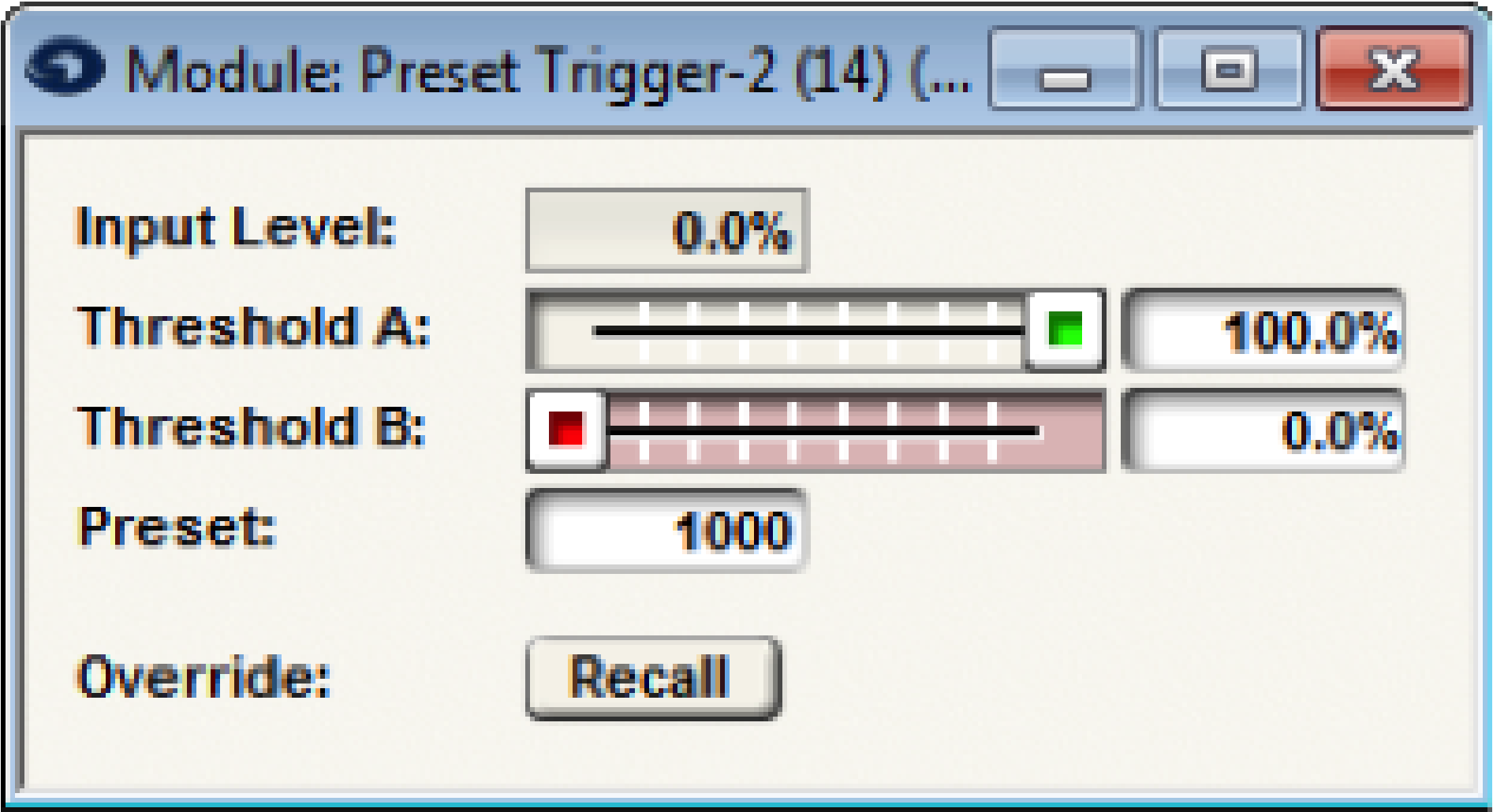
When radio button 2 is selected for Audio conference mode, Preset Trigger-2 is activated to configure the audio inputs and the 2 Input Logic module set to XOR will output False so that the projection screen will raise.
When button 3 is selected for Presentation mode, Preset Trigger-3 is activated to configure the audio inputs for the presentation and the 2 Input Logic module set to XOR will output TRUE triggering the Local Logic Output which will lower a projector screen for the presentation/PC VGA output.