


-
Type
- Dante
- Networking
- Control
-
System Management
- Composer Management Software
- SymVue Screen Authoring
- AV-Ops Center Remote Monitoring
- ARC-WEB Control Interface Signal Processing
- D100 AVoIP DSP Server
- Radius NX AVoIP DSP
- Prism AVoIP DSP
- Edge AVoIP DSP
- DSP I/O Expansion Cards
- Jupiter DSP
- Zone Mix 761 DSP I/O Connectivity
- xIO Bluetooth Endpoints
- xIO XLR Endpoints
- xIO AVoIP DSP Audio Expanders Control Systems
- T-Series Touchscreen Controllers
- W-Series Controllers
- Control Server
- xControl GPIO Expander
- ARC-Series Controllers
-
Type
- Dante
- Networking
- Control
-
System Management
- Composer Management Software
- SymVue Screen Authoring
- AV-Ops Center Remote Monitoring
- ARC-WEB Control Interface Signal Processing
- D100 AVoIP DSP Server
- Radius NX AVoIP DSP
- Prism AVoIP DSP
- Edge AVoIP DSP
- DSP I/O Expansion Cards
- Jupiter DSP
- Zone Mix 761 DSP I/O Connectivity
- xIO Bluetooth Endpoints
- xIO XLR Endpoints
- xIO AVoIP DSP Audio Expanders Control Systems
- T-Series Touchscreen Controllers
- W-Series Controllers
- Control Server
- xControl GPIO Expander
- ARC-Series Controllers
W-Series Controllers Tech Tips
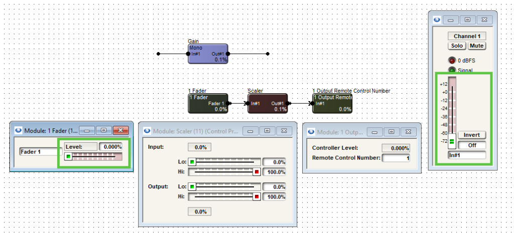
Limiting a fader to a specific dB range is easy within the Composer environment, whether using a Symetrix T-Series touchscreen, ARC-Series remote, or W-series remote. Third-party control, however, can be a bit more difficult if the third party doesn’t have their own inherent way to accomplish this task. Thankfully, with a small bit of logic circuitry we can emulate this range control. In this example, we are trying to limit the control of this gain module’s fader.
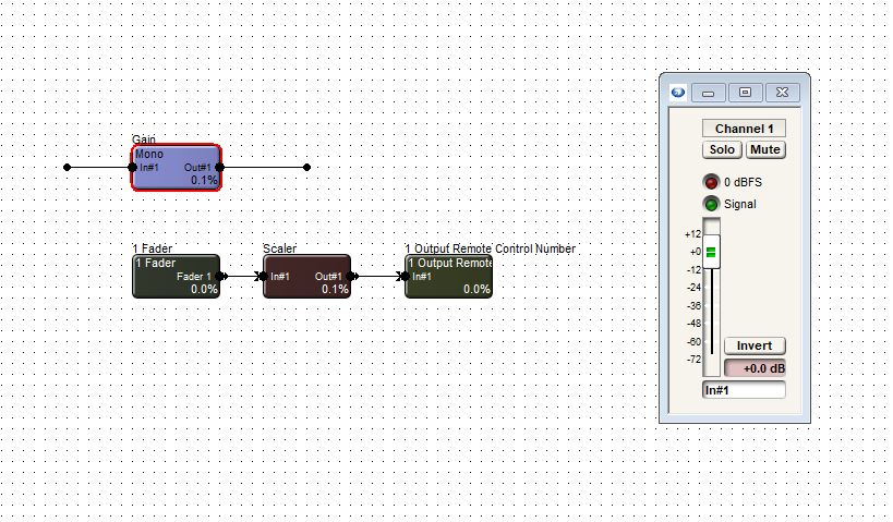
- First, drag in a control fader from the Control Inputs folder in the toolkit.
- Then, drag in a scaler from the control processes folder. Finally, drag in a one output remote control number module from the control outputs folder.
- Open each module, including the gain, and set the windows to be able to view all.
- In the one output remote control module, choose and enter an available remote control number. Then assign that same control number to the actual fader needing to be controlled.
- Now right-click on the logic fader and set it up to remote control, choosing another available remote control number. Note the chosen control number cannot be the same as the gain fader.
- We can’t see logic activity live while offline. If we push online we will see as we move the control fader from zero to 100% the gain fader moves as well. The point is to limit the effective movement of the gain fader in relation to the full scale movement of the logic fader.
- We can allow the control fader to fully scale on the scaler’s input. But if we adjust the output to a desired degree, we can limit the movement of the gain fader. In this case we’ll set the low output to 50% and the high output to 85.7%. This will give us a range of 0 to -30 dB. The scaler out values can be adjusted to match your system requirements
The control fader is what would be set up for the end user to control in the programming. It in turn controls the gain fader where the actual audio is passing through. Be aware that the representation will be in percentage, not dB.
While the dB level box from the gain module can be set up to remote control, the third-party controller should be consulted about how it will represent this value.
Limiting a fader to a specific dB range is easy within the Composer environment, whether using a Symetrix T-Series touchscreen, ARC series remote, or W-series remote. Third-party control, however, can be a bit more difficult-if the third party doesn’t have their own inherent way to accomplish this task.
Thankfully, with a small bit of logic circuitry we can emulate this range control. In this example, we are trying to limit the control of a gain module’s fader.
First, drag in a control fader from the Control Inputs folder in the toolkit. Then, drag in a scaler from the control processes folder. Finally, drag in a one output remote control number module from the control outputs folder.
Open each module, including the gain, and set the windows to be able to view all.
In the one output remote control module, choose and enter an available remote control number. Then assign that same control number to the actual fader needing to be controlled.
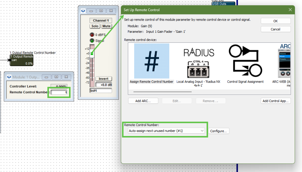
Note the control number output and the gain module fader are the same control number.
Now right-click on the logic fader and set it up to remote control, choosing another available remote control number. Note the chosen control number cannot be the same as the gain fader.
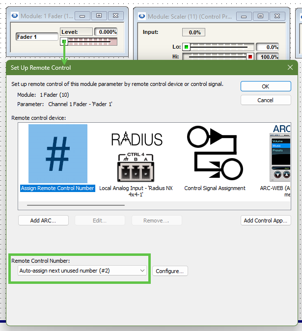
Note the control fader has a different remote control number assignment than the gain module fader.
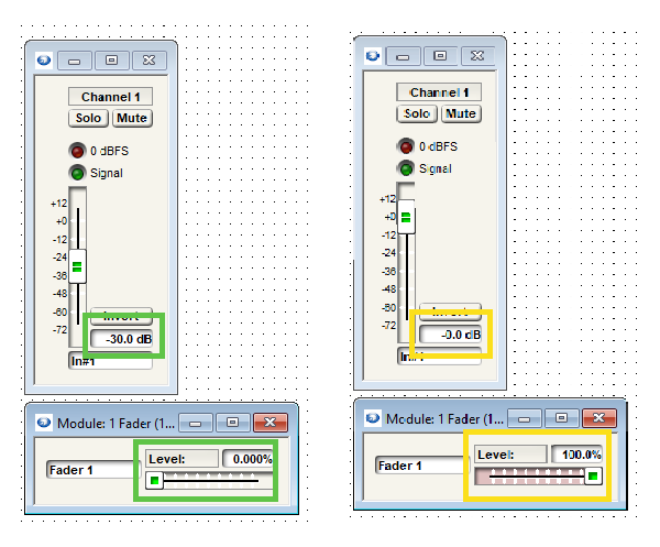
We can’t see logic activity live while offline. If we push online we will see as we move the control fader from zero to 100% the gain fader moves as well. The point is to limit the effective movement of the gain fader in relation to the full scale movement of the logic fader.
Note when the control fader is at 0% the gain fader is also at the lowest position, “off”.
We can allow the control fader to fully scale on the scaler’s input. But if we adjust the output to a desired degree, we can limit the movement of the gain fader.
limit 1
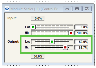
In this case we’ll set the low output to 50% and the high output to 85.7%. This will give us a range of 0 to negative 30 dB.
The scaler output values can be adjusted to match requirements of dB range(s).
The control fader is what would be set up for the end user to control in the programming. It in turn controls the gain fader where the actual audio is passing through. Be aware that the representation will be in percentage, not dB.
While the dB level box from the gain module can be set up to remote control for push value, the third-party controller should be consulted about how it will represent this value.
This article explains the differences between the selectable modes for the encoder, encoder button, and individual buttons for W-Series wall remotes.
Where do I find the different encoder button modes for my W-Series remote?
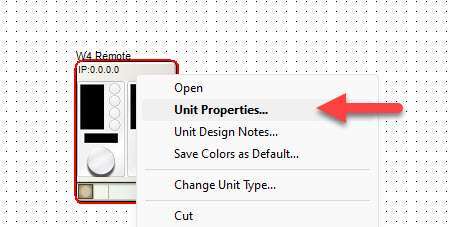
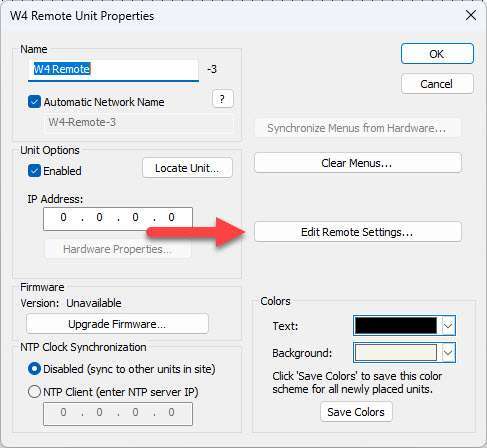
The available encoder button modes for each W-Series remote are found by right clicking the device in Site View, selecting “Unit Properties…”, and selecting “Edit Remote Settings…”.
Important: Not all encoder button modes are available on all W-Series remote models. This will be further explained below.
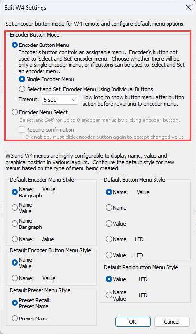
Breakdown of Encoder Button Modes
Encoder Button Menu: Single Encoder Menu
The “Single Encoder Menu” mode is the simplest of all the modes. It allows for control of a single menu with a turn of the encoder dial and a single button with a press of the encoder button.
Compatible models: W1, W3, W4
Encoder Button Menu: ‘Select and Set’ Encoder Menu Using Individual Buttons
The “‘Select and Set’ Encoder Menu Using Individual Buttons” mode allows for control of up to 4 menus with W3, and up to 8 menus with W4, by pressing a push-button switch to select a menu, then turning the encoder dial to adjust the value of the selected menu. The encoder button can also be used to control a single button in the design.
Compatible models: W3, W4
Encoder Menu Select
The “Encoder Menu Select” mode allows the user to cycle through up to 8 menus by pressing the encoder button. The value of the selected menu is then adjusted by rotating the encoder dial. This mode allows for control of multiple menus with W1. It also frees up the push-button switches on W3 and W4 to be used for other functions, as demonstrated in the above example.
Compatible models: W1, W3, W4
Note: None of the Encoder Button modes apply to W2 since it does not have an encoder.
Unlike ARC Series remotes, W Series remotes do not have a built-in method for setting upper and lower boundaries for fader control. Fortunately, there is a way to do this in Composer using Control Screens.
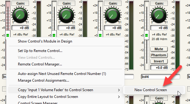
1. Right click the desired fader and select “Copy to control screen”. Create a new control screen if necessary:
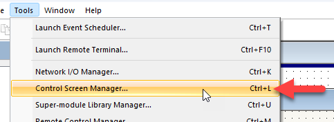
2. Go to Tools > Control Screen Manager:
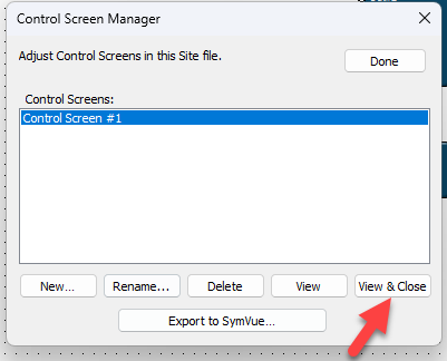
3. Highlight the control screen created in the first step and select “View & Close”:
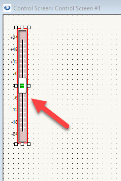
4. The fader in question will appear. Left click it to select it:
5. On the right side of the screen under “Properties”, locate “Control Range & Taper”:
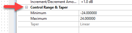
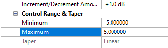
6. Under “Minimum” and “Maximum”, set the minimum and maximum values for the fader:
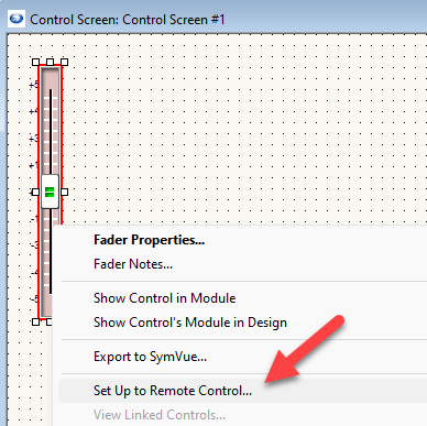
7. From here, right click the fader, select “Set Up to Remote Control”, and set it up to the W remote as normal:
This is a general-purpose step-by-step guide for connecting to Symetrix digital signal processors and related hardware with a PC. Please note that Symetrix only recommends using Windows 10 and above. Other operating systems are not officially supported at this time.
Step 1 – Install the right software for the device
Symetrix site design software is used to connect to Symetrix devices and is available to download, install, and run for free. The required software will depend on the devices that needs to be accessed:
Composer:
Current Symetrix open-architecture DSPs all use Composer, which can be downloaded here. These include:
- D100
- Radius
- Prism
- Edge
- Solus NX
Other Symetrix hardware that can be accessed through Composer will include:
- Endpoints and expanders (xIn, xOut, and xIO devices)
- T Series touch panels
- W Series wall remotes
- Control expanders (xControl, Control Server)
Important: To avoid errors when going online with the hardware, please download the version of Composer that matches the DSP’s firmware revision number as closely as possible. This number can be found by cycling through the system pages on the front LCD panel of the DSP.
Integrator Series:
Software for Symetrix’s current Integrator Series (closed-architecture) DSPs can be downloaded here. These include:
- Jupiter
- Zone Mix 761
Legacy Hardware:
Legacy open-architecture DSPs such as 8×8 DSP, Express CobraLink, and original Solus (non-NX) require SymNet Designer. This software has been discontinued and is no longer supported by Symetrix, but the final version (10.7) can be downloaded here. Software for all other legacy products, such as Zone Mix 760, AirTools-series, and Lucid-series, is no longer available for download.
Step 2 – Make sure the PC is on the right network
Once the correct software has been downloaded, the next step is to connect the PC to the device’s control network. If a DSP is Dante-enabled, make sure not to confuse the Dante ethernet port for the control ethernet port. Configuration of these devices through the Symetrix software is always done through the control port.
By default, Symetrix devices will obtain an IP address automatically, either from a DHCP server or, if a DHCP server is not available, by obtaining a link-local (169.254.x.x) IP address. Most Composer-enabled devices will display their IP address on the front LCD panel. Cycling through the system pages on the front LCD will additionally display the subnet mask. If a device has previously been configured with a static IP address, it can be reset to DHCP by briefly pressing the device’s reset button, which is usually recessed in the housing on the back of the device.
ncpa
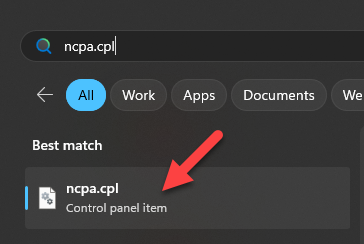
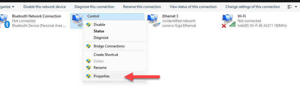
It is important that the PC’s network settings match those of the devices being used in the system. To check this, enter ‘ncpa.cpl’ in the Windows search bar to open the list of network adapters on the PC:
Right click the network adapter that will be used to connect to the device, select ‘Properties.
version
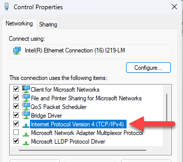
Then double click ‘Internet Protocol Version 4’:
address
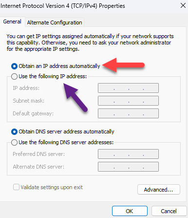
The network settings of the PC’s network adapter will display. If the Symetrix device is set to DHCP, select ‘Obtain an IP address automatically.’ Alternatively, a static IP address and custom subnet mask can be set here:
Important: Ensure that both the IP subnet and subnet mask of the network adapter match that of the device. If setting the PC to a static IP address, it must be a different/unused IP address on the network. If connected directly to the DSP with a static IP address, setting the PC to an address “right next to” the DSP usually safe. Example; if the DSP IP address is 192.168.100.50, set the PC to 192.168.100.51.
Step 3 – Locate the Symetrix hardware on the network
Once the PC is on the correct network, open the appropriate Symetrix software. The next steps will depend on the software being used.
Composer:
site
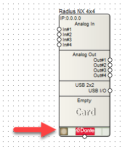
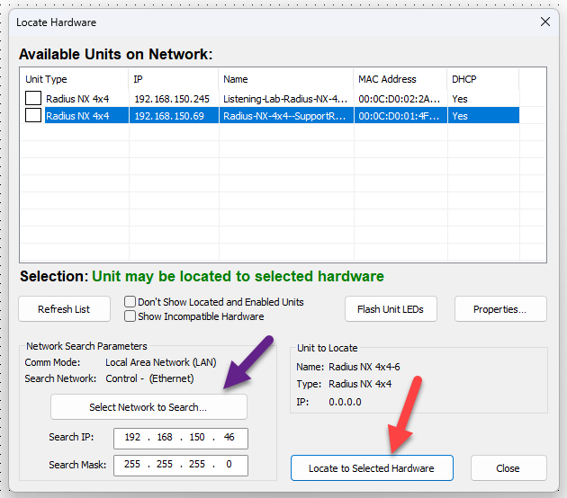
If a copy of the site file is available on the PC: Select the ‘File’ menu > Open and select it from File Explorer. In Site View, all located devices will have a checkmark in the lower left corner. If there is no checkmark present, click the empty box in the lower left corner of the device to open the Locate Hardware menu:
In the Locate Hardware menu, a list of available devices will appear. If necessary, click ‘Select Network to Search…’ to ensure that the correct network adapter is being used to scan for devices. Either double click the device in the list or highlight it and select ‘Locate to Selected Hardware’ to finish locating the device:
Repeat the above process for all devices in the Site View.
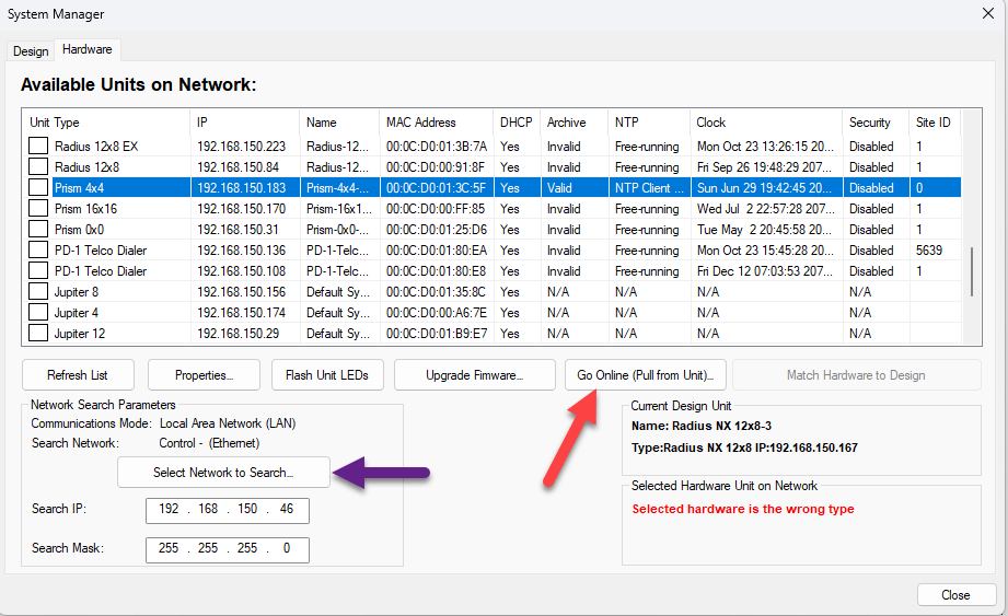
If the site file needs to be pulled from the unit:Go to the ‘Hardware’ menu > ‘System Manager’ > ‘Hardware’ tab. A list of all available units on the network will display. If needed, click “Select Network to Search…” to change the network being scanned for devices. Highlight the desired unit, then select ‘Go Online (Pull from Unit…)’:
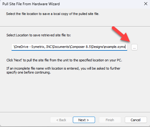
The Pull Site File From Hardware Wizard will appear. Select a location on the PC where the site file will be saved, then click ‘Next’:
Next, select either ‘Yes – Synchronize to All Changes’ to keep any changes made to the configuration while last online with this site file, or ‘No – Abandon Changes’ to revert to the archived version of the site file. ‘Show Advanced Options’ allows for more granular control over which changes are kept when synchronizing:
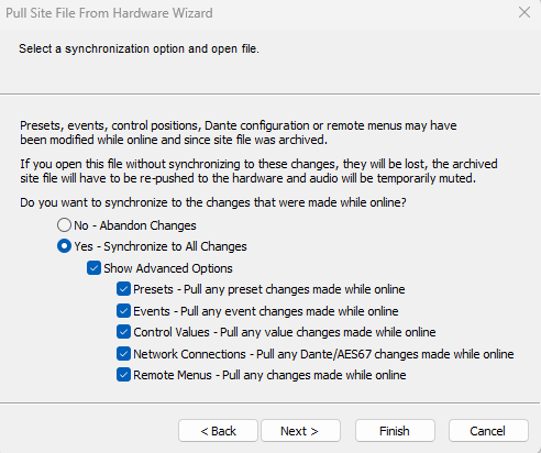
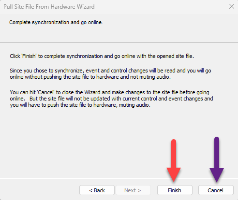
Select ‘Next’, then either select ‘Finish’ to go online with the site file as-is or select ‘Cancel’ to make changes to the site file before going online:
A note about Dante devices– Any Dante devices in the design must be located through a Symetrix DSP that has already been located:
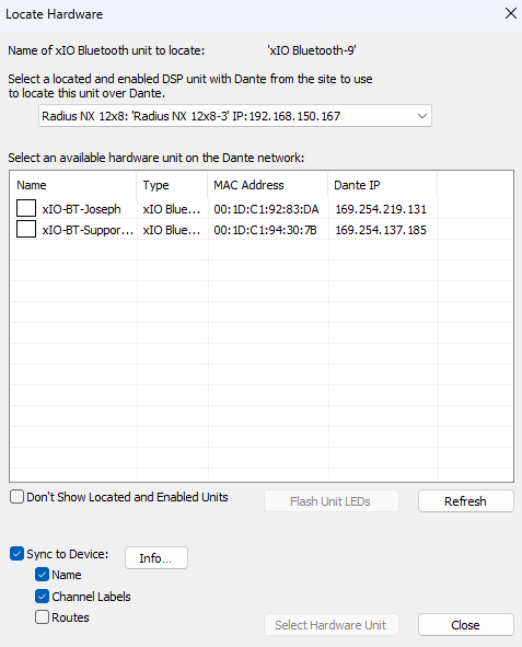
As of Composer 8.5, an xIO Updater/Configurator module may be added to the site view to configure Symetrix xIO Dante devices if a Symetrix DSP is not available. Symetrix recommends using separate networks for Dante and control.
Integrator Series:
Locating an Integrator Series DSP is done in the Connection Wizard of the Jupiter or Zone Mix 761 software. This can be done either by selecting ‘Existing File on Device’ > ‘Open Connection Wizard’ from the startup menu, or by selecting the Connection Wizard icon in the top ribbon:
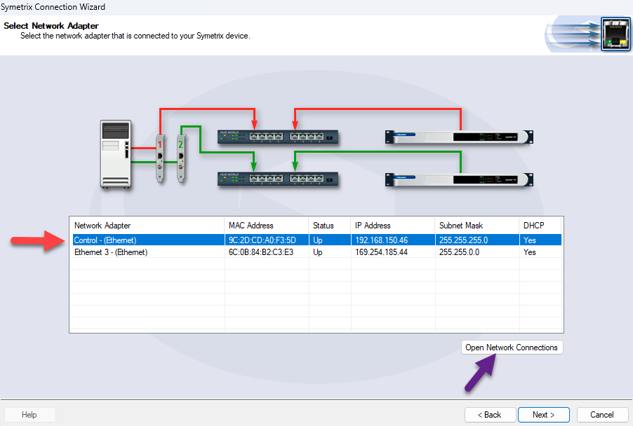
Once the Connection Wizard opens, select the option that best fits the connection type, then select ‘Next’. A list of the PC’s network adapters will appear. Select the one that is connected to the ethernet port of the device, then select ‘Next’. Select ‘Open Network Connections’ to show these network adapters in Windows Control Panel if any settings need to be changed:
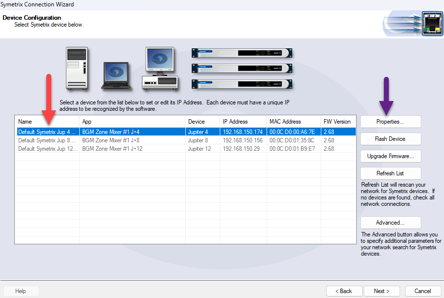
A list of devices will appear. Any devices not compatible with the current site file will be grayed out. Select the device, then select ‘Next’. Selecting the ‘Properties…’ button will allow a static IP address to be set for the device if desired:
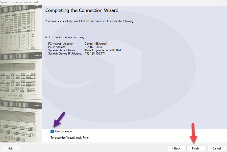
On the final screen, select ‘Finish’ to close the Connection wizard. To go online immediately, ensure the ‘Go online now’ box is checked:
Step 4 – Go online with the system
Composer:
online
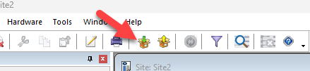
Once all devices in the site file have been located, select ‘Go online (push site file to hardware)’:
Note: The icon with the yellow arrow is for pulling the site file from the located hardware. Please see the passage entitled “If the site file needs to be pulled from the unit” in the previous section for more information on pulling the site file from the hardware.
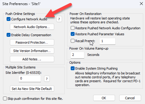
Next, the Site Preferences window will appear. These are generally advanced options that can be left alone, however if Dante routing is being managed in Dante Controller rather than in Composer, uncheck the box next to ‘Configure Network Audio.’ Click ‘OK’ to proceed:
dialogue
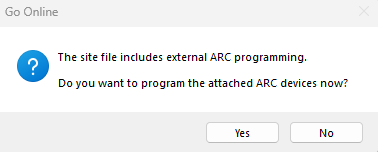
At this point, if the site file has not yet been saved to the PC, the File Explorer will appear and prompt for a filename and location to save the file to. If any ARC remotes are present in the design, a dialogue will appear and ask if all remotes should be programmed now. Regardless of whether ‘Yes’ or ‘No’ is selected here, the system will continue to push and go online:
success
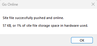
Once the site file has been successfully pushed, a success dialogue will appear. After clicking ‘OK’, the system volume will gradually ramp up unless the system mute is engaged:
Now that the system is online, parameters can be changed in real time, and signal meters will display their data. However, if any modules are moved, added, or deleted, or if any wires are changed, the system will automatically go offline. The site file must be re-pushed in order to go back online.
Important: The firmware versions of all devices in a Composer site file must match the version of Composer being used before going online with the system. If this is not the case, a message will appear prompting a firmware upgrade before the system can go online. Please refer to the Updating Firmware with Composer Tech Tip for further assistance.
Integrator Series:
After finishing the Connection Wizard, select the orange ‘Off-line’ button in the top ribbon. The drop-down arrow can be selected to choose which previously located device to go online with:
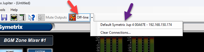
A prompt will then appear allowing the user to select whether to push the currently open configuration file to the device, or to pull the configuration file off of the device and save it to the PC.
Once the system is online, parameters can be changed in real time, and signal meters will display their data.
Integrator Series devices will operate normally with the factory firmware and should not require firmware updates to go online.
FAQs and Troubleshooting
“My device does not appear in the Locate Hardware menu.”
- Double check that the PC’s NIC and the Symetrix device are on the same network.
- Double check that the selected network in the Locate Hardware menu corresponds to the intended NIC.
- Change all octets of the IP address and subnet mask being searched for to ‘255’, uncheck the box next to ‘Don’t show located and enabled units’, and check the box next to ‘Show incompatible hardware’ in order to broaden the search as widely as possible.
- If a USB to ethernet adapter is being used with the PC, connect using a standard ethernet port instead if possible.
- Power cycle both the PC and the device.
- Re-seat the ethernet cable in both the PC and the device.
- Try a different ethernet cable.
- If the device is connected to the PC through a network switch, try a different switch port, or connect directly to the PC instead.
- If all else fails, disconnect the device from the network, reset its network settings by tapping the reset button once, then directly connect it to the PC (ensuring the PC is set to automatically obtain an IP address).
“I’m getting a ‘Failed to go online’ error message.”
- Disable Windows Defender Firewall and any third-party antivirus/firewall programs that may be blocking network traffic.
- Double check that the device firmware versions for all devices in the site file match the version of Composer being used (the first two numbers are most important).
- Power cycle both the PC and the device.
- If the device is connected to the PC through a network switch, try connecting directly instead.
- If a device cannot be located and is not needed in the site file, right click it and select ‘Disable Unit’.
“I can’t locate my Dante device.”
- Double check that the DSP is Dante-enabled by going to the ‘Tools’ menu > ‘Launch Remote Terminal’ > ‘Options’ menu > enable ‘Debug Mode’, then send the command info cards to the IP address of the DSP. If ‘Non-Dante Clock Card’ is displayed in the output under ‘Audio Network Card’, then the device does not have a Dante card installed. Please contact sales@symetrix.co to purchase one. If ‘No Card Present’ is displayed instead, there may be a problem with the Dante card.
- Double check that the Dante device is connected to the Dante port of the DSP.
- Connect the Device directly to the DSP’s Dante port, bypassing any network switches. If it can be located using this method, there may be a problem with the network.
- If all else fails, connect the PC to the Dante network, or directly to the Dante device, and verify that it appears in Dante Controller. If not, then there may be a problem with the Dante device, or it may be set to a static IP address outside of the Dante network.
“What does the yellow checkmark next to a device in Composer mean?”
A yellow checkmark means that the device is muted, while a green checkmark means that the device is unmuted.