


-
Type
- Dante
- Networking
- Control
-
System Management
- Composer Management Software
- SymVue Screen Authoring
- AV-Ops Center Remote Monitoring
- ARC-WEB Control Interface Signal Processing
- D100 AVoIP DSP Server
- Radius NX AVoIP DSP
- Prism AVoIP DSP
- Edge AVoIP DSP
- DSP I/O Expansion Cards
- Jupiter DSP
- Zone Mix 761 DSP I/O Connectivity
- xIO Bluetooth Endpoints
- xIO XLR Endpoints
- xIO AVoIP DSP Audio Expanders Control Systems
- T-Series Touchscreen Controllers
- W-Series Controllers
- Control Server
- xControl GPIO Expander
- ARC-Series Controllers
-
Type
- Dante
- Networking
- Control
-
System Management
- Composer Management Software
- SymVue Screen Authoring
- AV-Ops Center Remote Monitoring
- ARC-WEB Control Interface Signal Processing
- D100 AVoIP DSP Server
- Radius NX AVoIP DSP
- Prism AVoIP DSP
- Edge AVoIP DSP
- DSP I/O Expansion Cards
- Jupiter DSP
- Zone Mix 761 DSP I/O Connectivity
- xIO Bluetooth Endpoints
- xIO XLR Endpoints
- xIO AVoIP DSP Audio Expanders Control Systems
- T-Series Touchscreen Controllers
- W-Series Controllers
- Control Server
- xControl GPIO Expander
- ARC-Series Controllers
ARC-Series Controllers Tech Tips
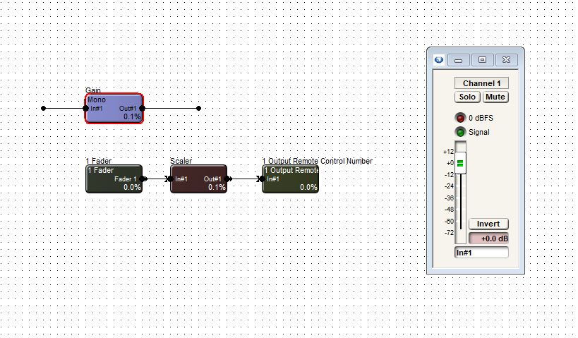
Limiting a fader to a specific dB range is easy within the Composer environment, whether using a Symetrix T-Series touchscreen, ARC-Series remote, or W-series remote. Third-party control, however, can be a bit more difficult if the third party doesn’t have their own inherent way to accomplish this task. Thankfully, with a small bit of logic circuitry we can emulate this range control. In this example, we are trying to limit the control of this gain module’s fader.
- First, drag in a control fader from the Control Inputs folder in the toolkit.
- Then, drag in a scaler from the control processes folder. Finally, drag in a one output remote control number module from the control outputs folder.
- Open each module, including the gain, and set the windows to be able to view all.
- In the one output remote control module, choose and enter an available remote control number. Then assign that same control number to the actual fader needing to be controlled.
- Now right-click on the logic fader and set it up to remote control, choosing another available remote control number. Note the chosen control number cannot be the same as the gain fader.
- We can’t see logic activity live while offline. If we push online we will see as we move the control fader from zero to 100% the gain fader moves as well. The point is to limit the effective movement of the gain fader in relation to the full scale movement of the logic fader.
- We can allow the control fader to fully scale on the scaler’s input. But if we adjust the output to a desired degree, we can limit the movement of the gain fader. In this case we’ll set the low output to 50% and the high output to 85.7%. This will give us a range of 0 to -30 dB. The scaler out values can be adjusted to match your system requirements
The control fader is what would be set up for the end user to control in the programming. It in turn controls the gain fader where the actual audio is passing through. Be aware that the representation will be in percentage, not dB.
While the dB level box from the gain module can be set up to remote control, the third-party controller should be consulted about how it will represent this value.
Limiting a fader to a specific dB range is easy within the Composer environment, whether using a Symetrix T-Series touchscreen, ARC series remote, or W-series remote. Third-party control, however, can be a bit more difficult-if the third party doesn’t have their own inherent way to accomplish this task.
Thankfully, with a small bit of logic circuitry we can emulate this range control. In this example, we are trying to limit the control of a gain module’s fader.
First, drag in a control fader from the Control Inputs folder in the toolkit. Then, drag in a scaler from the control processes folder. Finally, drag in a one output remote control number module from the control outputs folder.
Open each module, including the gain, and set the windows to be able to view all.
In the one output remote control module, choose and enter an available remote control number. Then assign that same control number to the actual fader needing to be controlled.
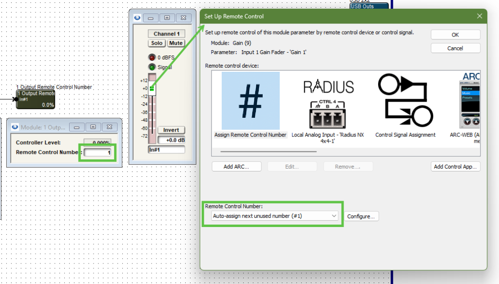
Note the control number output and the gain module fader are the same control number.
Now right-click on the logic fader and set it up to remote control, choosing another available remote control number. Note the chosen control number cannot be the same as the gain fader.
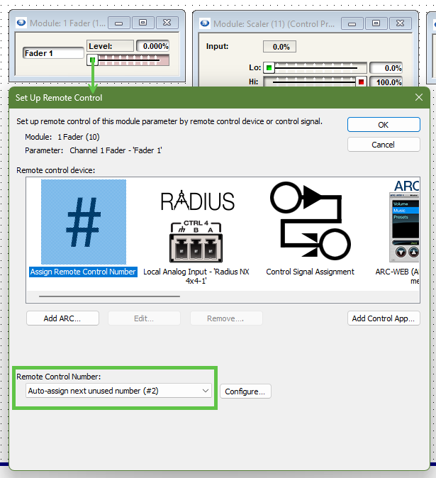
Note the control fader has a different remote control number assignment than the gain module fader.
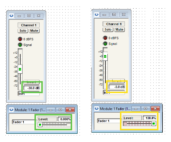
We can’t see logic activity live while offline. If we push online we will see as we move the control fader from zero to 100% the gain fader moves as well. The point is to limit the effective movement of the gain fader in relation to the full scale movement of the logic fader.
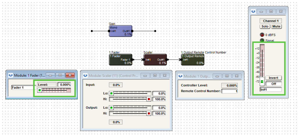
Note when the control fader is at 0% the gain fader is also at the lowest position, “off”.
We can allow the control fader to fully scale on the scaler’s input. But if we adjust the output to a desired degree, we can limit the movement of the gain fader.
limit 1
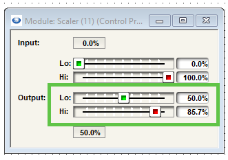
In this case we’ll set the low output to 50% and the high output to 85.7%. This will give us a range of 0 to negative 30 dB.
The scaler output values can be adjusted to match requirements of dB range(s).
The control fader is what would be set up for the end user to control in the programming. It in turn controls the gain fader where the actual audio is passing through. Be aware that the representation will be in percentage, not dB.
While the dB level box from the gain module can be set up to remote control for push value, the third-party controller should be consulted about how it will represent this value.
ARC remotes are a powerful and intuitive form of control for systems using Symetrix DSPs. This Tech Tip will walk through setting up stereo Source Select and Volume control for the Jupiter on an ARC-WEB for the BGM Zone Mixer app. The process is nearly identical for ARC-2e.
Note: this set up assumes stereo output as well.
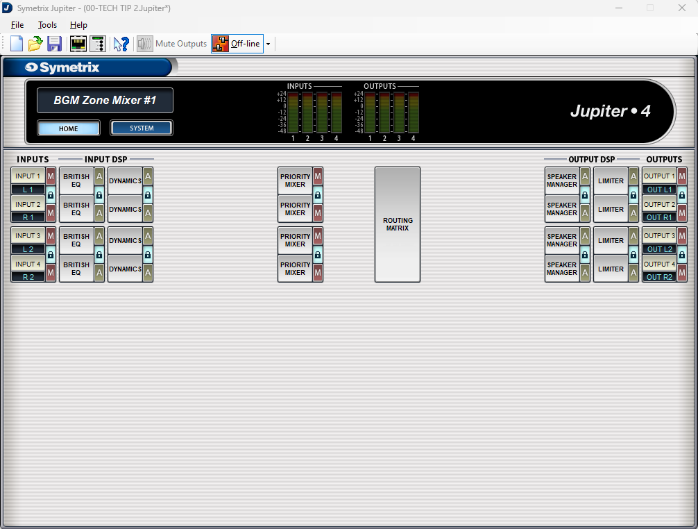
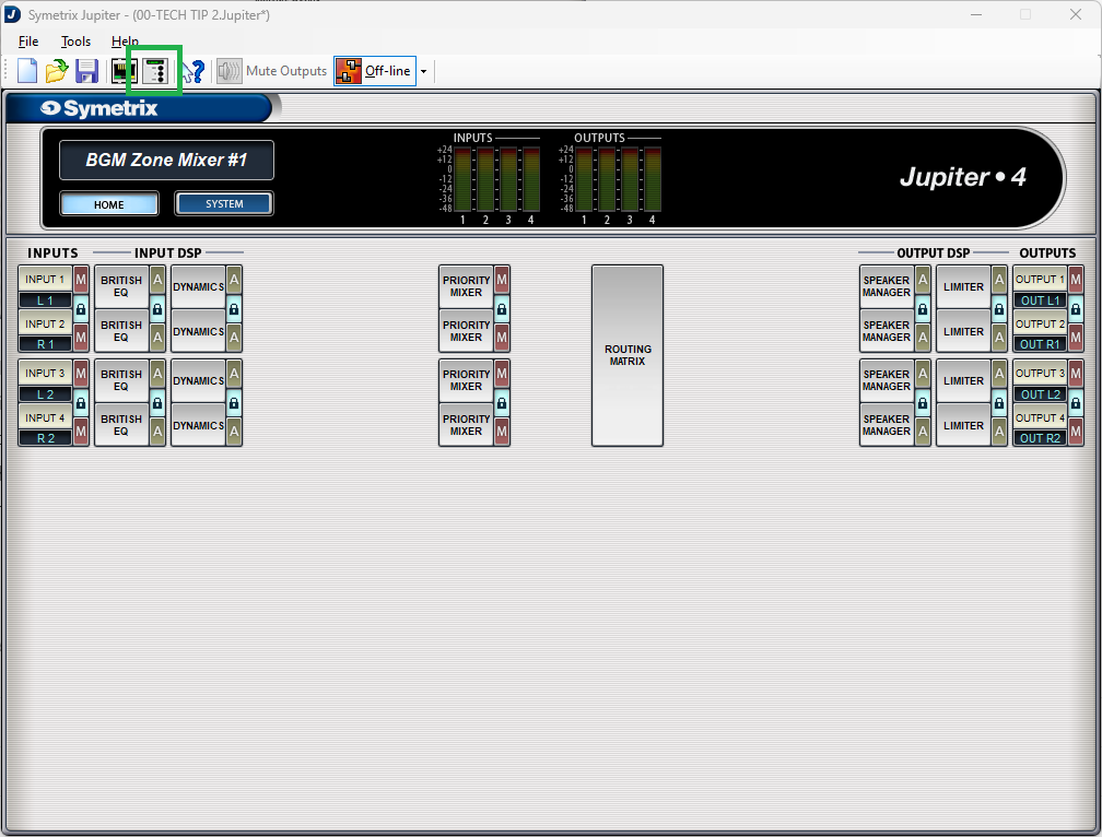
Looking at the home page for the BGM Zone Mixer we will be focusing on two major sections.
The Routing Matrix:

And the Priority Mixers:

The channels have already been labeled for this tech tip and we can see that there are two stereo inputs and two stereo outputs; noted as L/R 1, L/R 2, as well as Out L/R 1 and Out L/R 2 respectively.
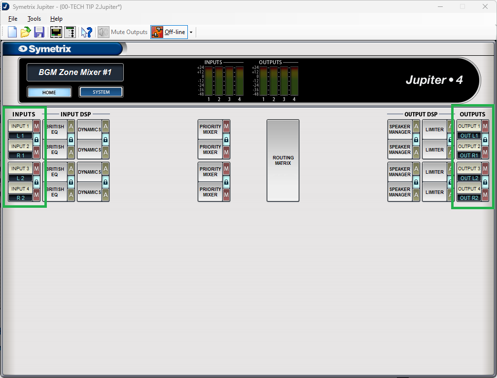
Also notice that all of the “lock” buttons have been engaged, locking channels 1 and 2, and 3 and 4. This is key to getting the proper control for stereo source select and volume control.
Open up Priority Mixer 1. Notice that the title of this page says “Priority Mixer 1/2”. This is noting that Priority Mixers 1 and 2 are linked, so actions in one affect the other.
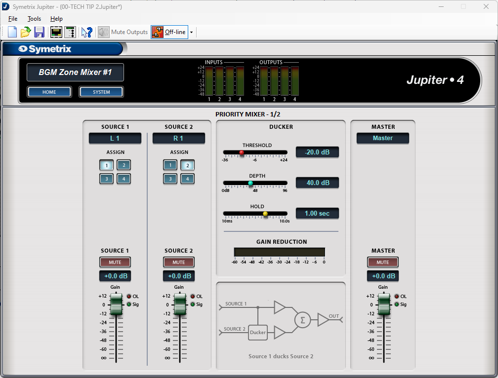
Note that Source 1 assign button has input 1 (L1) selected and its fader is at 0dB (we won’t be focusing on Source 2 in this Tech Tip). Now open up Priority Mixer 2.

We see that it has the same page name, Priority Mixer 1/2, and that the fader position is the same at 0dB, but the assign button is set to input 2 (R1). This represents that Priority Mixer 1 has input 1 (left) selected and Priority Mixer 2 has input 2 (right) selected. Change the assign button to input 4 and move the fader to the Off position. Now go back and look at Priority Mixer 1.
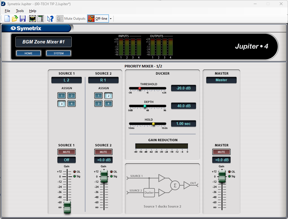
We see that the assign button has changed to input 3 (L2) and the fader has moved from 0dB down to the off position. This is what linking the two channels does.
Note: Odd number priority mixers should only select odd numbered assign buttons, while even numbered priority mixers should only select even numbered assign buttons. Reversing these will technically work, but the other locked priority mixer will do the opposite. For example, if priority mixer 1 selected input 2, then priority mixer 2 would select input 1.
Now that we have an understanding of how the source selection works within the priority mixers, go back to the home page and open the Routing Matrix.
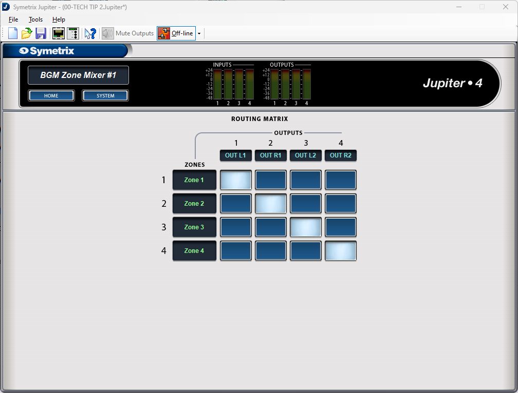
Notice that there are Zones labeled that connect to outputs through cross-points. These zones relate directly to the priority mixers; zone 1 is priority mixer 1, zone 2 is priority mixer 2, and so on. With the stair-step pattern of the cross-points, we can then say that Priority Mixer 1 is Zone 1 which is Output 1. The same for Priority Mixer 2, Zone 2, and Output 2, and the rest. For ease, you are welcome to relabel the zones to Priority 1, 2, and so on.
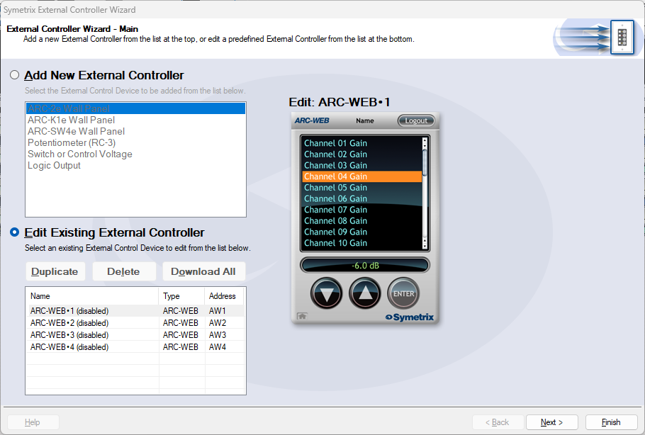
Now let’s set up the source select control. Go back to the home page and open up the External Controller Wizard.
Select Edit Existing Controller, highlight an available ARC-WEB and click Next.
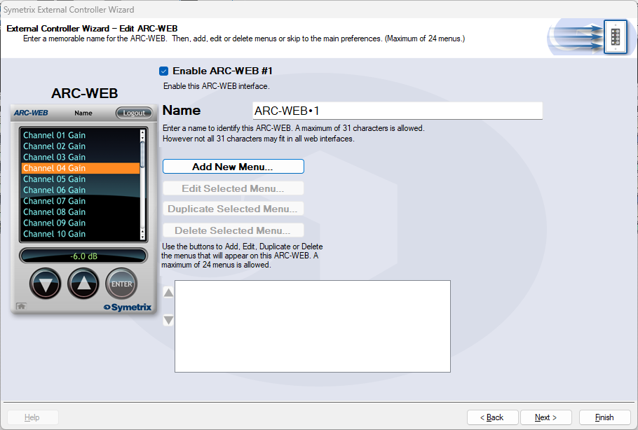
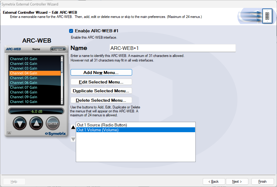
Enable the ARC-WEB at the top, rename the menu if necessary, and click Add Menu.
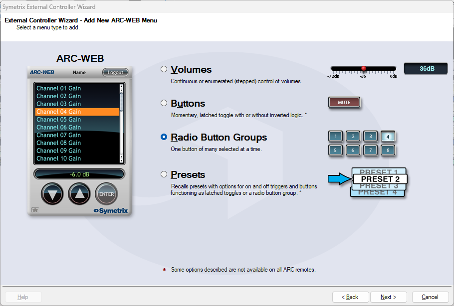
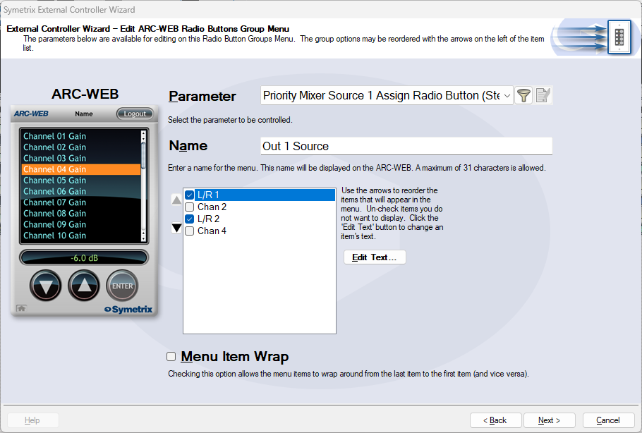
Select Radio Button Groups and click next.
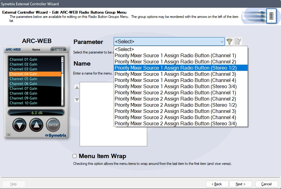
In the Parameter drop-down, select Priority Mixer Source 1 Assign Radio Button (Stereo 1/2). This will tell the Jupiter software that the source select will act in unison between Priority Mixers 1 and 2.
Name the menu appropriately. Remove options 2 and 4 from the channel list. This will prevent someone from accidentally reversing some inputs. In effect, there wouldn’t likely be a critical failure if this happened, however it is redundant and unnecessary to allow the Left audio channel to be in the Right output channel, and vice versa.
Re-name Chan 1 and 3 appropriately. In this case we’ll just use L/R 1 and L/R 2, but this could be a bluetooth source, third-party media player, or other stereo source. Since the Priority Mixers are acting together, Chan 2 and 4 are not necessary. Then click next.
We are brought back to the menu home page. Click Add New Menu to add a Volume Control. This time, choose volumes and click next.

Select Continuous or Enumerated appropriately and click next.
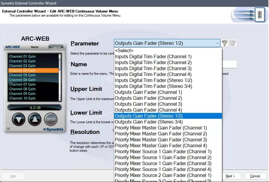
In the Parameter drop-down, select Outputs Gain Fader (Stereo 1/2). This will control the two gain faders for analog Outputs 1 and 2.
Note: While this is not the recommended parameter to control zone volume (as it is post-limiter and can put the sound system at risk of being overdriven with signal), there is not currently a way to control the faders from two Priority Mixers with ARC-WEB or ARC-2e by selecting one of them above. Consider setting the upper limit to the output fader control to prevent the overdriving of the amps/speakers downstream.
Name the menu and set the limit parameters appropriately and click next.

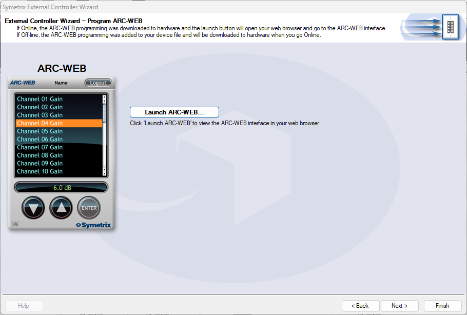
We are again brought back to the menu home page with two menus listed for source and volume control. Now we can test our work by clicking next and setting parameters along the way, until we arrive at the page that allows us to Launch ARC-WEB.
Click launch and a Browser window should open with your ARC-WEB where you can test the source selection and volume control. You must be online with the Jupiter DSP to test this programming. Programming for ARC-2e will allow for a simulator interface that can be tested with.
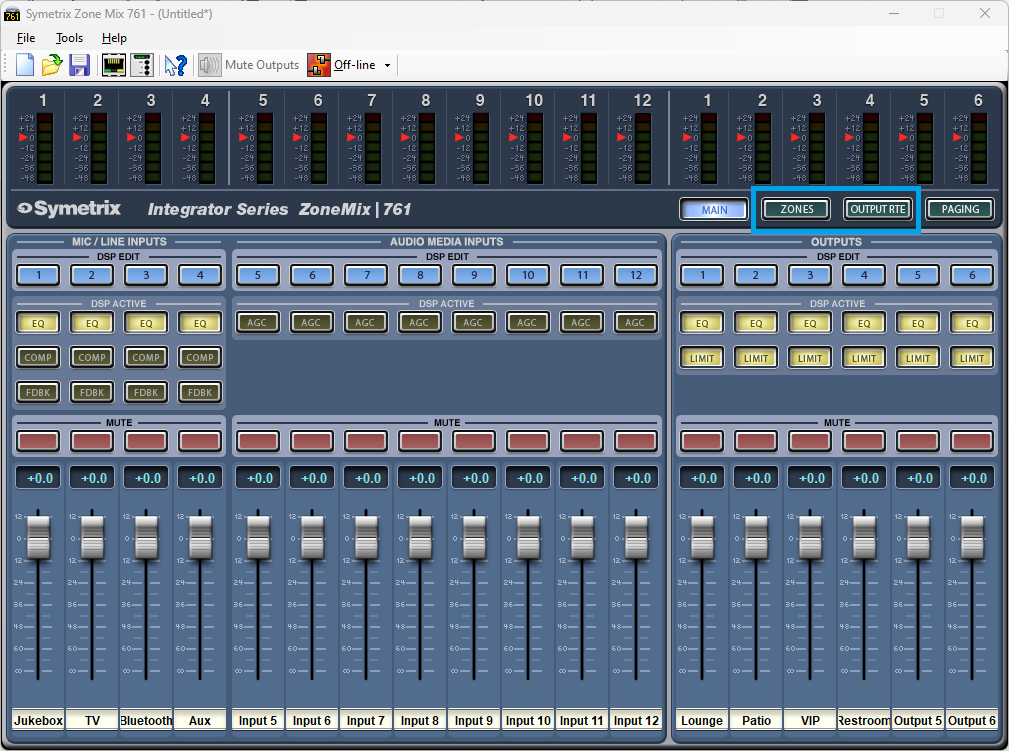
ARC remotes are a powerful and intuitive form of system control for systems using Symetrix DSPs. This Tech Tip will walk through setting up zone Source Select and Volume control for the Zone Mix 761 on an ARC-2e. The process is nearly identical for ARC-WEB.
Starting at the Zone Mix 761 software homepage, there are two main areas to focus on.
- Zones; these are where control parameters are located for source select and volume.
- Output RTE; this is where we connect signal flow from Zones to the analog outputs, effectively making each Zone a direct control for an analog output.
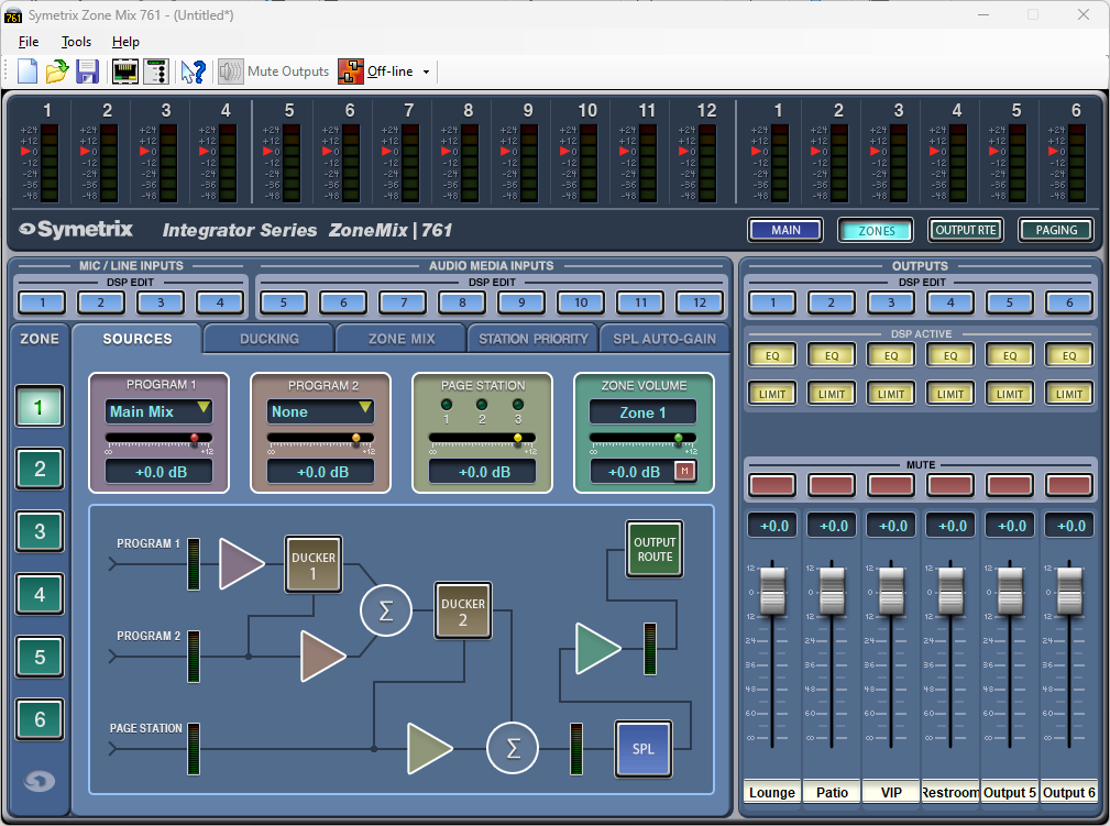
In the Zones area, under the Sources tab there are two source selections, Program 1 and Program 2. Program 2 ducks Program 1, and Page Station ducks both Program 1 and 2 as shown in the signal flow diagram.
Either Program 1 or Program 2 can be used for the zone source select depending on what the system needs. This example assumes there is no ducking/priority paging involved and will use Program 1 for the zone source. Program 2 can be set to None.
Effectively, the zone volume can be controlled by either the Program 1 slider or the Zone Volume slider. There may be a reason later to add a paging microphone or something similar, so it programmatically makes sense to use the Zone Volume slider.

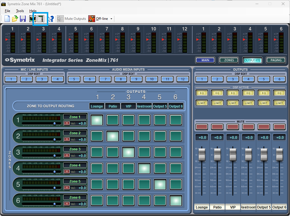
Looking in the Output RTE area, notice the stair step pattern to the cross-points. This is how we connect Zone 1 to Output 1, Zone 2 to Output 2, and so on. This way each Zone represents actual Output areas in the venue. In this configuration, we can consider Zone 1 that Lounge, Zone 2 the Patio, and so on.
The volume slider on each zone channel is the same control as the Zone Volume slider in the Zones Sources tab.
Open the External Controller Wizard.
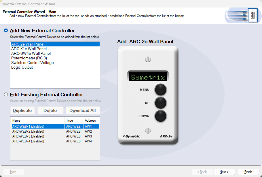
There are two lists here. This Tech Tip will be programming a new ARC-2e. With Add External Controller selected, highlight the ARC-2e and click Next.
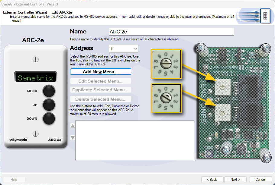
The name of the ARC-2e can be edited here, which we will call System Control in this example. Ensure that the ARC-2e is addressed correctly according to the dials on the back of the unit. When ready, click Add New Menu.
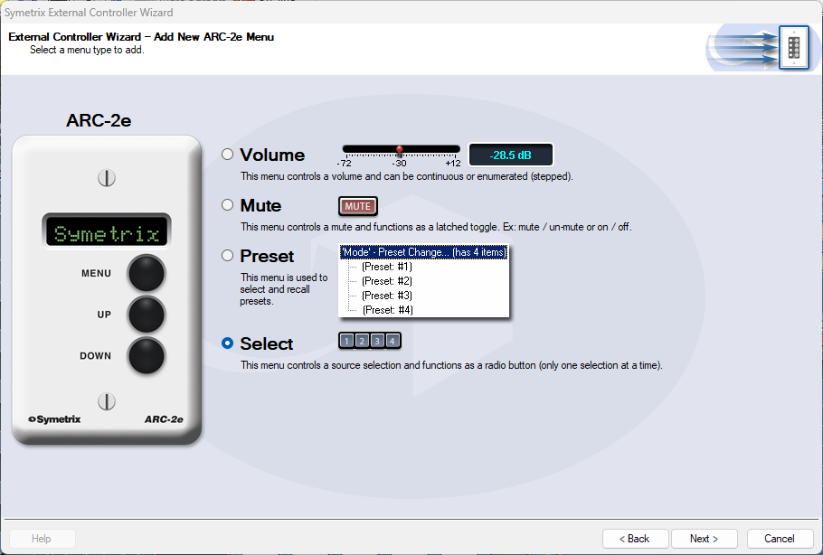
First, we’ll set up source select for Zone 1 (Lounge). Choose the “Select” option and click Next.
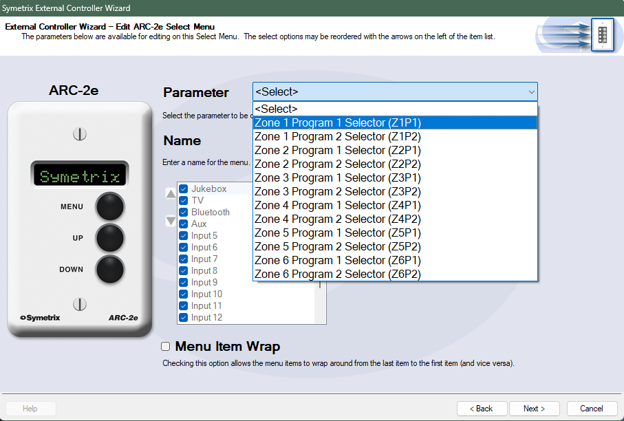
The Parameter selection is where we define the parameter for source selection in Zone 1. Choose Zone 1 Program 1 Selector. The Name can also be edited, which will be Lounge Source here.
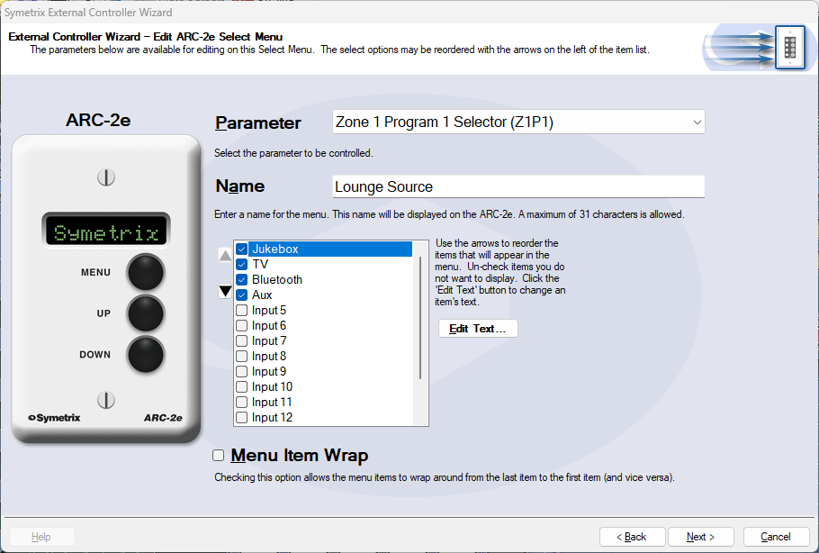
The checkbox list below Name is where we decide which analog input sources should be included as options for the Lounge Source. Uncheck any sources that should not be included and click Next. We are returned to the ARC-2e home menu where we can see the Lounge Source menu listed.
Next, we’ll set up a Zone Volume control. Click Add New Menu.
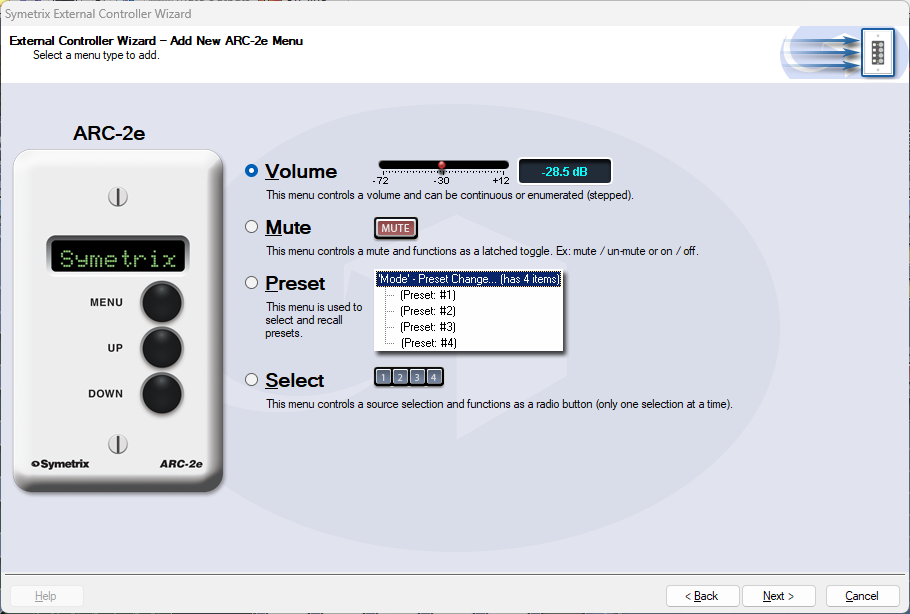
Select the Volume option and click Next.
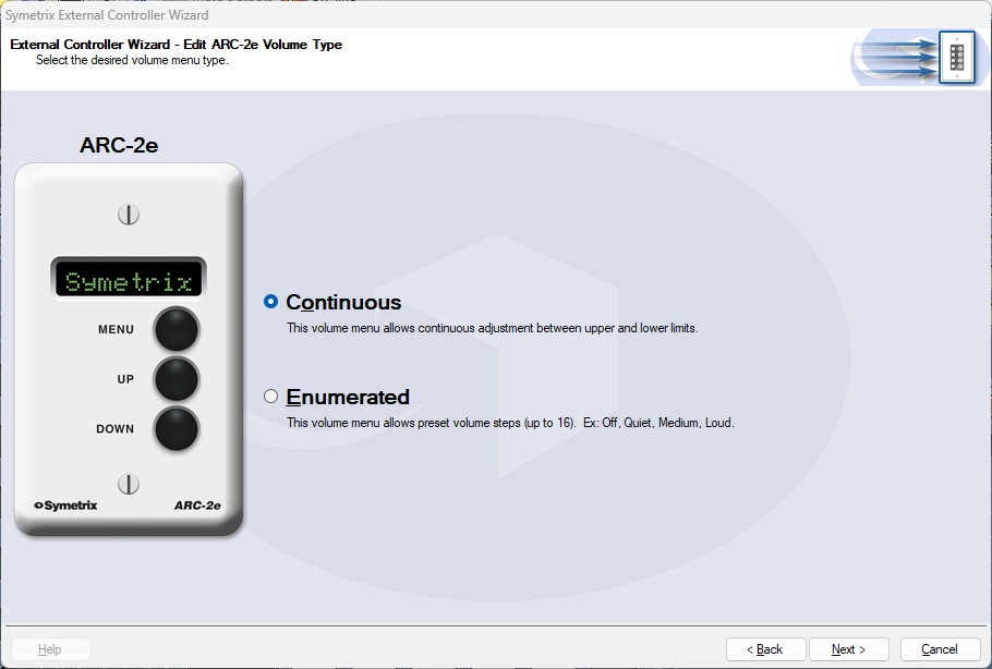
In most cases Continuous will be the better option for more precise control. However, Enumerated may be a more intuitive option for user control. In this example, we’ll select Continuous and click Next.
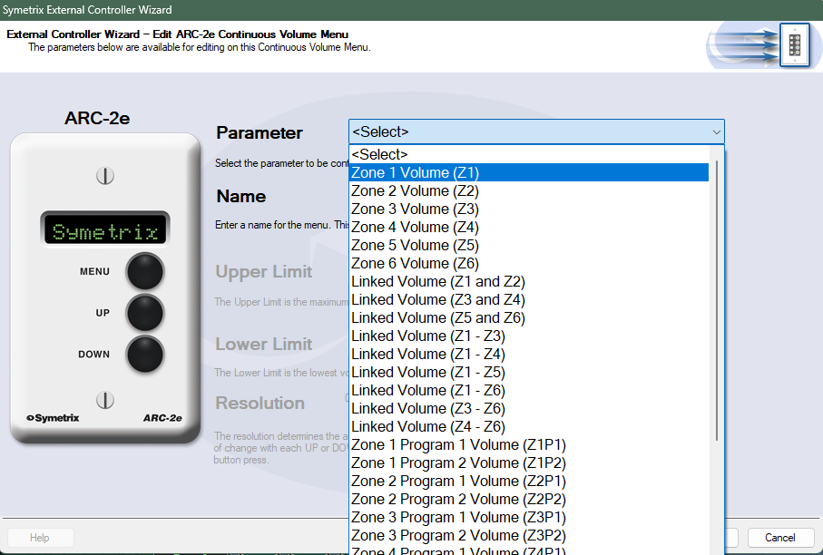
Select Zone 1 Volume to connect this control to the Zone Volume slider in Zone 1. The control Name and upper/lower limits can also be edited, which will be Lounge Volume and leave as default respectively in this example. Click Next.
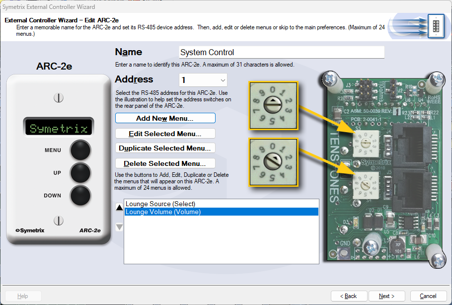
We are returned back to the ARC-2e home menu where we can see both Lounge Source and Lounge Volume listed.
Click Next for more options related to the ARC-2e unit itself, and Next again for a section that offers the ability to Simulate the ARC-2e, to test your work.
Note: Some parameters may act oddly in simulation mode. This is a known issue.
When finished programming all other relevant zone controls, click Finish to save.
The ARC-K1e is a simple, intuitive ARC remote that can be used for many parameters. However, the large majority of use cases are likely volume control. In this example we will couple an ARC-K1e with an ARC-EX4e that will act together as volume control and input selection.
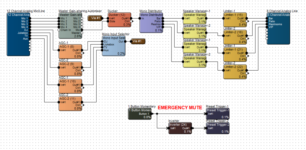
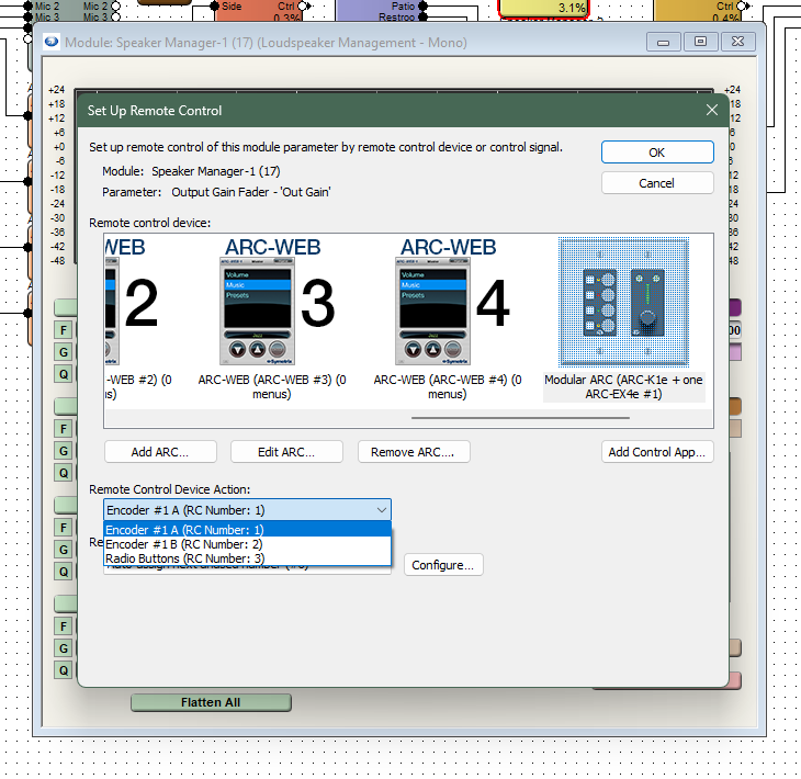
This site file has four speaker zones; Bar, Patio, Restrooms, and VIP. Open up the first Speaker Manager that flows to the Bar zone. Right-click on the module gain fader and select Set Up Remote Control.
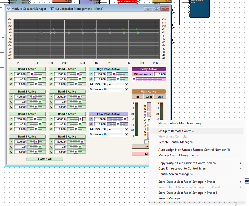
Scroll to the right in the Remote Control Devices area and select Add New ARC. If you already have an ARC-K1e or ARC-K1e + EX4e added, it should be displayed in this list.
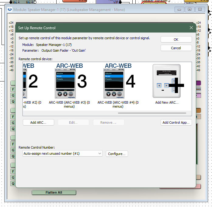
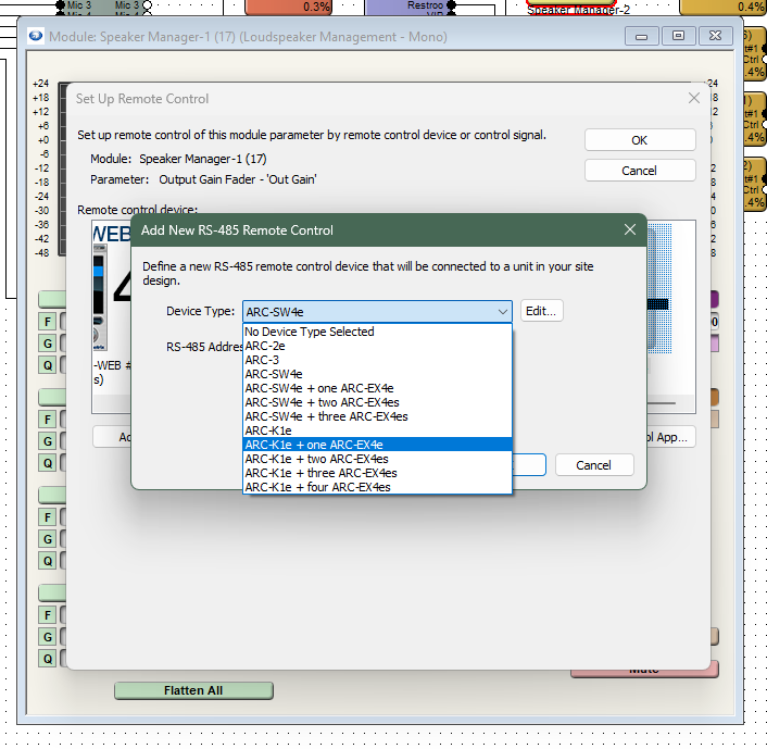
Select the ARC-K1e + one ARC-EX4e from the drop-down list.
Now select Encoder #1 A. This will assign the first Speaker Manager gain fader to the A side of the K1e knob control. Do the same for the second Speaker Manager gain fader, but select Encoder #1 B to set it to the B side of the K1e knob control.
Note: the other two zones would require a second ARC-K1e. If two or more zones are to be controlled together, set the gain faders to the same control number. These faders will control in unison.
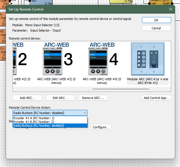
Now, open up the Mono Input Selector module, right-click on the slider at the bottom, and then choose Set Up to Remote Control.
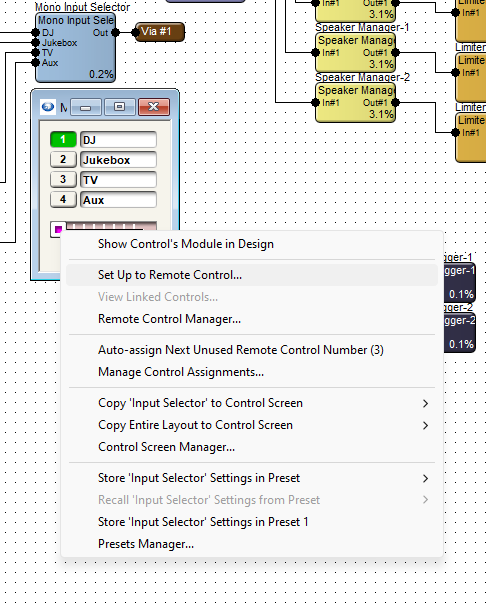
Choose the Modular ARC from the list and assign the Input Selector slider to the Radio Buttons option. This will allow the four input selections to relate to the four buttons on the EX4e, in the same order that they appear in the module.
Push the design and program the ARC remote, and go online to test the control.
ADDITIONAL NOTE:
There are may more ways to take advantage of the ARC-K1e in combination with EX4e or SW4e. This Tech Tip is a basic example of setting up these remotes. Refer to the Help File > Module ARC Programming for more information.
By using SymNet Designer, the entire line of Symetrix Modular ARC panels can be made to control any parameter within your Jupiter device beyond those already available in the External Controller Wizard. You can also utilize expansion ARCs such as the EX4 and EXK giving you even more possibilities. Here’s
how:
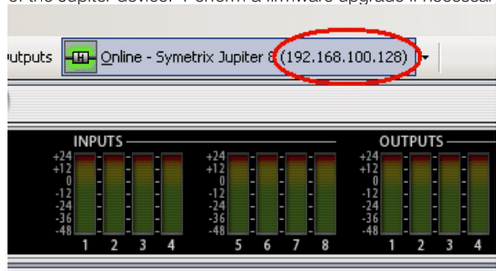
1) Connect the ARC and host PC to your Jupiter device.
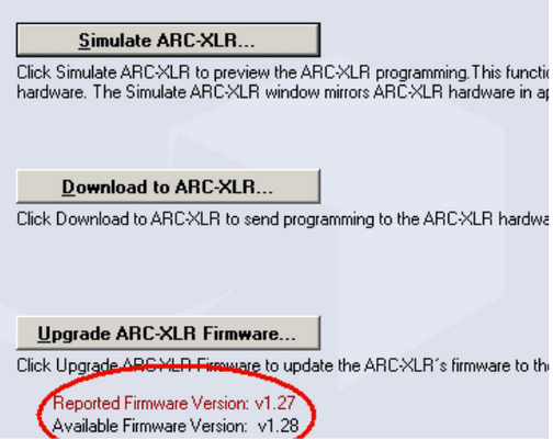
2) Launch the latest version of the Jupiter software and discover the device on your network using the Connection Wizard. After completing the Connection Wizard, take note of the IP address of the Jupiter device. Perform a firmware upgrade if necessary.
3) Ensure you can communicate with the ARC using the External Controller Wizard. Upgrade the ARC firmware if necessary.
4) Go to the Tools menu and choose Store Preset. Click Custom Preset and Choose parameters. From within this dialog browse to the control(s) you wish to access from the ARC and write down the controller number (far right column).
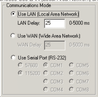
5) Launch the latest version of SymNet Designer. Go to the File menu and choose Preferences. Under Communications Mode choose Use LAN (Local Area Network) and then click OK
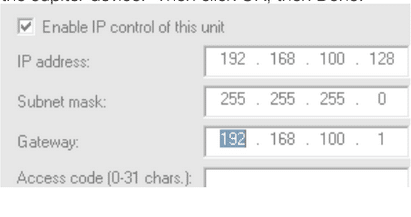
6) Go to the Edit menu and choose Site Ethernet Preferences. Click on Ring #1 and then click Edit Unit Settings. Enter the IP information of the Jupiter device. Then click OK, then Done.
7) To ensure that SymNet Designer is communicating with the Jupiter device over IP go to the Hardware menu and choose Upgrade Firmware/Hardware Settings. Look for the name of the Jupiter device listed under Hardware. If it shows Not Present, then double check the IP address of the Jupiter and return to step 6. *Note, do not upgrade firmware or take any action from this dialog.
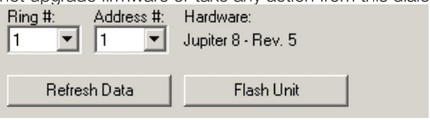
8) To ensure that SymNet Designer is communicating with the Jupiter device over IP go to the Hardware menu and choose Upgrade Firmware/Hardware Settings. Look for the name of the Jupiter device listed under Hardware. If it shows Not Present, then double check the IP address of the Jupiter and return to step 6. *Note, do not upgrade firmware or take any action from this dialog.
9) Now that we’ve established communication, let’s program the ARC. Go to the Tools menu and choose Controller Manager. Click New RS-485 Device and choose the appropriate ARC.
10) Edit the newly created ARC and enter the controller numbers (noted from step 7) in the appropriate sections of the Edit Modular ARC menu, i.e., Switches, Knobs, etc. When all controller numbers have been added to your ARC, download to the ARC from within the Controller Manager. This will send the programming to the remote. If it will not download, double check that the RS-485 address shown on the rotary dipswitches on the back of the ARC match the address in the Edit Modular ARC menu.
11) Finally, with the Jupiter software in focus, test the controls on the ARC and watch for the Jupiter GUI to follow those control changes. Note, custom programmed ARCs will not appear in the Jupiter External Controller Wizard and you must ensure that all ARCs on the network have unique RS-485 addresses regardless of how they were programmed.
An ARC’s current requirements vary depending on the voltage supplied to it. For example, an ARC-2e with a 15 VDC supply uses approximately 115 mA, while with 8 VDC it uses approximately 230 mA. As the voltage varies from 15 VDC to 8 VDC, the current requirement increases accordingly. Note: The voltage range for all ARCs is 8 to 30 VDC. Symetrix units’ ARC ports provide 24 VDC.
The following table provides at-a-glance cable length limitations based on DC power (the table is not relevant if only RS-485 is distributed) and assumes 24 gauge CAT5/6 cabling. The lengths for multiple ARCs on a single chain assume equal distance for each cable segment between ARCs. This table is intended for quick reference only. For more detailed configuration scenarios, Symetrix has made available a Microsoft Excel spreadsheet to help system designers determine power requirements based upon cable length, number of ARCs, and the power supply to be used. This spreadsheet can be downloaded from the Symetrix Technical Support pages here.
Here is a table noting cable segment length limitations for ARC power over CAT-5e cable:
| Number of ARCs on Chain | ARC-3 | ARC-2e | ARC-K1e | ARC-SW4e |
| 1 | 3000 ft | 3000 ft | 3250 ft | 3250 ft |
| 2 | 1100 ft | 1200 ft | 3000 ft | 3000 ft |
| 3 | 550 ft | 700 ft | 1250 ft | 1250 ft |
| 4 | 200 ft | 250 ft | 400 ft | 400 ft |
*Note– These numbers are based on ARCs attached to an Edge, Prism, Radius, or other device supplying 24V and at least 500 mA.
If power is not distributed over CAT5/6, each RS-485 chain is limited to 1000 feet / 304 m in a star network configuration and 4000 feet / 1219 m in a daisy-chain network configuration. Longer distances may be possible using third party RS-485 extender products.
The total number of ARCs that can be daisy chained and fed power from an ARC port may be limited depending on ARC type and cable distances. An ARC-PSe Rack Mount Power Supply may be used to accommodate a larger number of ARC Wall Panels.
WARNING: When designing an ARC network, one must be careful not to double power any ARCs. If all pins on the CAT5/6 connections are used, power can travel over the CAT5/6 cable and reach any ARC on that particular chain. Power over CAT5/6 could potentially come from the ARC that is powered locally (via a custom wired cable using the pinout above) and then daisy-chained via CAT5/6 to other ARCs, or from a powered ARC port on a Symetrix unit or ARC-PSe (preferred). In general, we recommend only supplying power from the start of a chain (a Symetrix unit or an ARC-PSe).
This article contains information and guidelines related to controlling Symetrix and third-party products using IP, Dante, serial, and other technologies.
IP Control Network Guidelines
- The maximum number of connected IP devices is 128. This includes DSPs, W Series, and T Series controllers.
- Up to six TCP sessions can be active at one time.
- If a seventh TCP/IP connection is initiated, the least recently used session will be automatically closed. Control systems should avoid closing and re-opening TCP connections if possible. Keeping a single TCP session open to send multiple commands through will result in much better performance than opening and closing a session for each command.
- To control Symetrix DSPs with Ethernet:
- Command strings are sent as the payload of a UDP/IP or a TCP packet. The following rules should be observed in sending commands:
- Commands should be sent to UDP or TCP port number 48631 to the unit’s IP address. The IP address may be found using the Connection Wizard or on some units’ front panel displays.
- Commands should be formatted exactly as defined in the Composer help file and include a carriage return that terminates the command.
- Command strings may or may not include a zero-termination character.
- Commands should not be broken up across multiple packets.
- If high-reliability communications are required, responses to commands should be analyzed for success.
- Command strings are sent as the payload of a UDP/IP or a TCP packet. The following rules should be observed in sending commands:
Control of Third-Party Devices via the Dante Control Network
Supported Third-Party Dante Device Limitations
- The number of Dante devices (except Shure – see below) that can be located by or referenced by (switch input and LED output use) from a single DSP unit is limited to 24.
- The number of Shure devices that can be located by or referenced by (switch input and LED output use) a single DSP unit is limited to 4.
Control Methods
TCP/UDP/HTTP Control
Third-party devices that are controlled by TCP or UDP strings or binary code can be controlled from a Symetrix DSP either by using a Network String Module available in the Composer toolkit or by the use of an Intelligent module. If bidirectional communications or control using HTTP is needed, then an Intelligent module is required.
IR Control
Symetrix has tested and verified that the Global Cache IP2IP/IP2IR and their other IR interfaces work with Symetrix products. Communicate using binary Mode to Global Cache units. Text does not work.
Serial Control
Radius and Edge have a single serial port. If using a DSP without a serial port or if additional serial ports are needed, use an xControl or Global Cache IP2LS/IP2SL-P/WF2SL.
Contact Closure or Voltage Control
Included natively in Symetrix DSPs. If more connections are needed than provided with the DSP add xControl Control Expanders. In addition to analog/logic control inputs/logic outputs, the xControl also adds two additional serial ports.
Control Server
The Wi-Fi access point built into the Control Server only passes data to the Symetrix control network. It cannot be used to access another network.
ARC Controls
Power Limitations
The total number of ARCs that can be daisy-chained and fed power from an ARC port may be limited depending on ARC type and cable distances. An ARC-PSe Rack Mount Power Supply may be used to accommodate a larger number of ARC Wall Panels.
| CABLE SEGMENT LENGTH LIMITATIONS FOR ARC POWER OVER CAT5 CABLE | ||||
| ARC TYPE | ||||
| Number of ARCs on chain | ARC-3 | ARC-2e | ARC-K1e | ARC-SW4e |
| 1 | 3000’ | 3000’ | 3250’ | 3250’ |
| 2 | 1100’ | 1200’ | 3000’ | 3000’ |
| 3 | 550’ | 700’ | 1250’ | 1250’ |
| 4 | 200’ | 250’ | 400’ | 400’ |
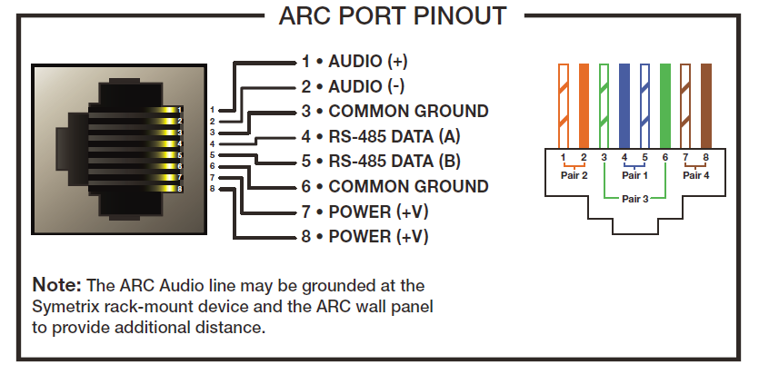
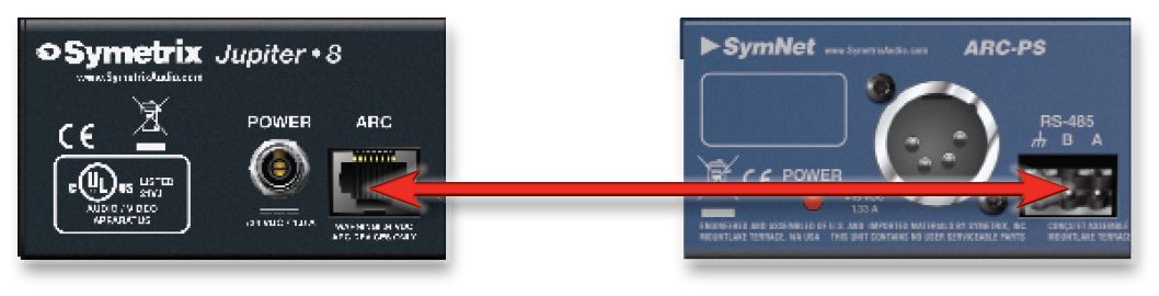
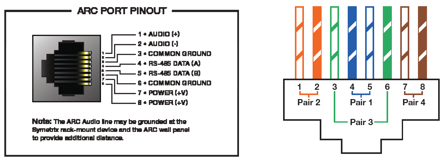
Connecting ARCs to Jupiter hardware is simple using the (RJ-45) ARC port on either the front or back of the device. These ports not only provide communication (RS-485) data, but also +24 VDC power. If the required number of ARCs exceeds the current limits of the Jupiter ARC port(s), an ARC-PS can be used to power additional ARCs. Connecting a Jupiter ARC port to the RS-485 port on the ARC-PS is easily accomplished by following one of two methods.
Method 1: Modify an Off-the-Shelf CAT-5 cable
- Cut off one end of the CAT-5 cable.
- Wire three of the wires to a terminal block connector such that:
A = Blue.
B = Blue/White.
Ground = Green.
Note: Blue/White is twisted with Blue, and Green/White is twisted with Green. - Connect the RJ-45 to the ARC port on Jupiter.
- Connect the terminal block connector to the RS-485 port on the ARC-PS.
- Connect your ARCs to the RJ-45 ports on the ARC-PS.
- Program your ARCs with the External Controller Wizard in the Jupiter software.
Method 2: Make Your Own Cable
- Crimp an RJ-45 connector to one end of a CAT-5 cable.
Note: Only pairs 4+5 and 3+6 are necessary, so STP cable could be
substituted by sharing the ground. - Wire three of the wires to a terminal block connector such that:
A = pin 4.
B = pin 5.
Ground = pins 3 and 6. - Connect the RJ-45 to the ARC port on Jupiter.
- Connect the terminal block connector to the RS-485 port on the ARC-PS.
- Connect your ARCs to the RJ-45 ports on the ARC-PS.
- Program your ARCs with the External Controller Wizard in the Jupiter software.
NOTE: Refer to the ARC Network Design topic in the Jupiter help file for more information.
Overview
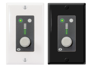
The Modular ARCs are a series of two base remotes and one expansion device. The Modular ARCs, as their name implies, are expandable within a familiar Decora® form factor. Note that Cooper brand Decora® plates are recommended for use with the Modular ARCs due to their better fit.
The Modular ARC devices
ARC-K1e
The ARC-K1e modular remote control wall panel features a push-button rotary encoder that provides simple control of two parameters in the Symetrix DSP hardware. The 8-segment LED ladder on the ARC-K1e provides instant user feedback, clearly showing relative volume level. Two additional LEDs illuminate to indicate which of the two available controls are active. All control assignments, including parameter limits and firmware version upgrades, are handled by the software included with Symetrix DSP hardware.
A single channel RJ-45 connection provides power and data to the ARC-K1e. ARCK1e has an “idle” mode option for light-sensitive environments like theaters. Hardware lockout pins accommodate an installer supplied key switch. Furnished with a standard white single gang Decora® faceplate and splash resistant overlay. The ARC-K1e fits in standard US wall boxes (sold separately) for in-wall or surface mount applications.
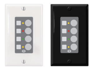
ARC-SW4e
The ARC-SW4e is a modular remote control wall panel with four switches that are programmable as momentary, latched or radio buttons. ARC-SW4e provides simple control over mutes, source selection and preset triggering. Corresponding tricolor LEDs provide user feedback. LEDs may be linked to buttons, or, LEDs and buttons may be programmed independently. Symetrix DSP software performs all control assignments, including button and LED
functionality, parameter limits and firmware version upgrades.
A single channel RJ-45 connection provides power and data to the ARCSW4e. ARC-SW4e has an “idle” mode option for light-sensitive environments like theaters. Hardware lockout pins accommodate an installer supplied key switch.
arc 1
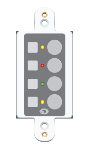
Furnished with a standard white single gang Decora® faceplate and splash resistant overlay. The ARC-SW4e fits in standard US wall boxes (sold separately) for in-wall or surface mount applications.
ARC-EX4e
The ARC-EX4e is identical in form to the ARC-SW4e. Couple the ARC-EX4e with ARC-K1e or ARC-SW4e to expand remote control capabilities. The ARCEX4e cannot be used standalone nor can it be combined with an ARC-2e. Up to four ARC-EX4e may be combined with an ARC-K1e and up to three ARC-EX4e may be combined with an ARC-SW4e. The ARC-EX4e is furnished with a splash resistant overlay and mounts into a Decora® faceplate (sold separately) alongside its Modular ARC host.
| To these base Modular ARC units, one can add a maximum of: | ARC-EX4e |
|---|---|
| ARC-K1e | 4 |
| ARC-SW4e | 3 |
Modular ARC Anatomy
The Modular ARCs, true to their modular construction, utilize an expansion board (which provides the user interface) and a brain board (which provides the system connections, device addressing, processing, etc.). Each Modular ARC has one brain board and an expansion boards attached. The brain board possesses the
host processor, system connection and power jacks, configuration jumpers and device address rotary switches. To quickly identify a brain board, look for the RJ45 jacks. The anatomy of a brain board is outlined below:
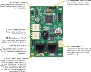
System Connection
ARCs connect to the system via an RS-485 bus. This is typically via a single CAT5 cable that carries both RS-485 data and power. For full information, refer to the ARC Network Design topic in the help file of SymNet Composer and/or SymNet Designer.
RS-485 Termination
The ARC Wall Panels feature an RS-485 termination jumper. Jumper J4 at the bottom left of a Modular ARC’s brain board enables and disables termination. Jumping pins 1 and 2 = terminated. For maximum signal integrity, it is advisable to terminate the last ARC device in the chain if the total length of the chain is over 200 feet.
Note: Never terminate a single RS-485 bus at more than two devices.
Device Addressing
Every RS-485 device connected to the same RS-485 bus must be uniquely identified. The Modular ARCs use two rotary switches (S1 and S2) to designate one of 99 device addresses. S1 determines the device’s ones address and S2 determines the device’s tens address. For example: to set an Modular ARC to device address 24, you would place S1 in the 4 position and S2 in the 2 position. If the remote has had its RS-485 address changed, be sure to power cycle the remote. The recommended way to power cycle the remote is to actually power cycle the DSP, as yanking the ARC cable out may cause voltage spikes and other issues.
Before performing a power cycle, always be sure that the amplifiers hooked up to the units outputs are powered off.
Hardware Lockout
J6 on the Modular ARC provides a hardware lockout feature. Installers may wire a key switch to this jumper to provide a simple means to secure a remote in an installation. This function may be inverted or selectively enabled/disabled from the Remote Control Manager.
Modular ARC Expansion Bus
As detailed previously, J2 allows the daisy-chaining of expansion boards which, together with the brain board, can make up to a 5-gang Modular ARC panel (one knob and up to 16 switches). Each board must have a unique Board ID. This ID is set by S5 on the ARC-EX4e.
The ARC-EX4e’s Board IDs will range from 0 to 3 when connected to an ARCK1e or 1 to 3 when connected to an ARCSW4e. (An ARC-K1e has a board ID of 4 while an ARC-SW4e has a Board ID will of 0 from the factory).
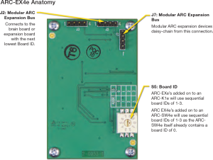
If adding an EX4e to an SW4e, the expansion bus address of the EX4e will be addressed to (1), as the control board underneath the brain board on the SW4e is actually an EX4e and it will be addressed to (0) already. If adding an EX4e to a K1e, address the expansion address of the EX4e to (0), as the control board underneath the brain board on the K1e is a rotary encoder, not another EX4e as it is when expanding an SW4e.
In order to be effective, end user control systems need to be simple and intuitive. Some might even call the previous sentence an understatement.
In the audio world decibel (also known as dB) is the standard measurement of sound level and makes perfect sense when viewed on a fader or volume control on a control system. For the end user, reading a volume control’s current position in dB might be much like reading a foreign language, not making much sense unless they have received formal training on what the dB scale means.
Rather than providing training manuals to explain a dB scaled volume control, it may often times prove much easier to simply provide the volume control to the end user as a percentage, or % value instead.
When using Symetrix hardware this is easily accomplished with some creative programming in Composer. Here are the steps for creating volume menus in an ARC-2e or ARC-WEB that read in percent.
Step 1.
checked
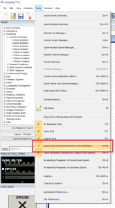
First, be sure “Super-impose Assigned Controller Numbers” is checked under the Tools dropdown in Composer.
Step 2.
Next, assign controller numbers to the volume faders of a Gain, Mixer, Matrix, or Room Combiner in Composer using either:
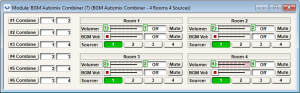
a. “Auto-assign Next Controller Number” (see Figure 1.1)
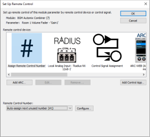
b. “Set up to Remote Control… > Generic Controller Numbers
Assignment” (see Figure 1.2) to the dB faders in which the end user
will be given access to control with the ARC-2e or ARC-WEB. Do
not add these assignments to the ARC-2e or ARC-WEB at this time.
figure 1.1
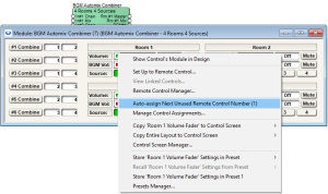
Figure 1.1: Auto-assigning a controller number to a BGM Room Combiner volume fader.
Figure 1.2
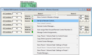
Figure 1.2: Set up to Remote Control… > Generic Controller Numbers Assignment
Step 3.
step 3
After assigning volume faders a controller number, the assignment should be visible on the module’s user interface.
numbers
See the green rectangles with control numbers.
Step 4.
Next, from the Composer toolkit, from Control Modules>Control Inputs drag out a “1 Fader” module into the design.
step 4
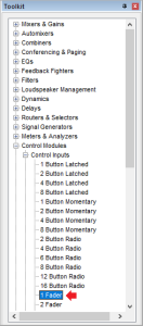
Next, from the Composer toolkit, from Control Modules>Control Inputs drag out a “1 Fader” module into the design.
Step 5.
Next, open the 1 Fader module and assign a controller number to the control fader. Notice the control fader reads in % instead of dB.
step 5
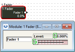
Next, open the 1 Fader module and assign a controller number to the control fader. Notice the control fader reads in % instead of dB.
Step 6.
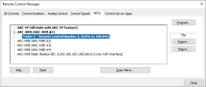
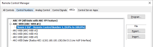
Now open the Remote Control Manager under the Tools dropdown (or Ctrl+M). Notice the volume fader assignments and the 1 fader assignment in the Control Numbers tab.
step 6
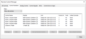
Now open the Remote Control Manager under the Tools dropdown (or Ctrl+M). Notice the volume fader assignments and the 1 fader assignment in the Control Numbers tab.
Step 7.
Click on the 1 Fader control assignment to select it and click Set Up Remote Control…
step 7
Click on the 1 Fader control assignment to select it and click Set Up Remote Control.
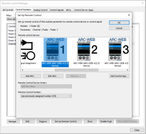
Step 8.
Scroll to select the Remote Control Device of choice, an ARC-WEB or ARC-2e, and then click OK. This will add a 0-100% menu item into the selected remote control device.
Step 9.
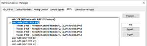
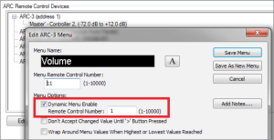
Move to the ARCs tab and expand the ARC-WEB or ARC-2e associated with these controls and then double click on the Fader 1 menu, or click to highlight and hit the Edit… button near the bottom of the window to access the Edit ARC Menu.
step 9
Move to the ARCs tab and expand the ARC-WEB or ARC-2e associated with these controls and then double click on the Fader 1 menu, or click to highlight and hit the Edit… button near the bottom of the window to access the Edit ARC Menu.
Step 10.
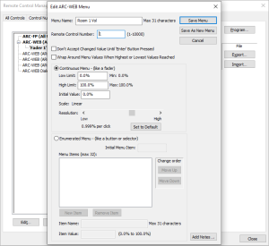
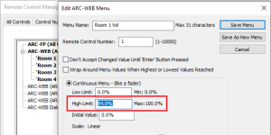
Change the Menu Name and Controller Number to the desired dB fader assignment from Step 3. In this example Controller #1 was for Room 1 Volume. Note, the controller number must match the assignment but the Menu Name can be labeled anything. This menu name is what the end user will see on the ARC display.
step 10
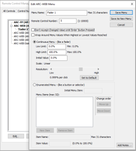
Change the Menu Name and Controller Number to the desired dB fader assignment from Step 3. In this example Controller #1 was for Room 1 Volume. Note, the controller number must match the assignment but the Menu Name can be labeled anything. This menu name is what the end user will see on the ARC display.
Step 11.
step 11
Hit the Save Menu button.
Manager
Step 12.
Repeat steps 4-12 for all subsequent volume fader assignments that will read in % value, each BGM Combiner fader having its own 1 Fader control input module.
Step 13.
When completed with the % value ARC programming. Push the site file to the SymNet system and program the RS-485 network.
Step 14.
step 14
The end user will now see % values for volume controls rather than dB values.
Step 15.
Note: On a -72dB to +12dB volume fader, if it is desired to scale a volume control so that 0dB is the max level an end user can turn up the gain, set the High Limit to 84%.
The Symetrix ARC-PSe provides serial control and power distribution over standard CAT5/6 cable for systems with more than 4 ARCs, or, when any number of ARCs are located long distances from an Integrator Series, Jupiter or SymNet DSP unit. A halfrack form factor conserves rack space, or, if preferred, the ARC-PSe may be surface mounted. All mounting hardware is included. The incoming serial control signal coming from the DSP is received by the ARC-PSe on a RJ-45 input connector, and then power and signal are distributed via 8 RJ-45 output connectors. The use of off-the shelf CAT5/6 cable and RJ-45 connectors reduces installation time and materials costs.
Features
- Distributes power and data to multiple ARC wall panels via eight RJ-45 connectors over long distances.
- Connects directly to any Integrator Series, Jupiter or SymNet DSP unit using standard CAT5/6 cables.
- Supports flexible ‘star’ configuration, ‘daisy-chain’, or a hybrid of the two. Versatile
- Versatile half-rack design. All hardware is included to mount 1 or 2 in a single rack space or to surface mount.
ARC-PSe Hook Up Considerations:
- The ARC-PSe has a total of 1000 mA available and which is shared across all 8 ports.
- Each ARC port on the ARC-PSe can use as much as 500mA.
- When daisy chaining one ARC-PSe to another ARC-PSe it is not necessary to have power on the CAT5/6 cable. In fact, the power is stripped off at the ARC input on the ARC-PSe; however, having power present on the CAT5/6 takes away from the 1000 mA that are shared amongst all 8 ports. As such, it is recommended that the power pins, 7 and 8, be omitted from the CAT5/6 cable, leaving all 1000 mA of power for the other 7 ARC ports.
- The ARC-PSe does not act as a RS-485 repeater. This means no ARC may be farther than 4000 ft / 1219 m from the host DSP no matter what configuration is used.
- The ARC Power Calculator is available to assist with ARC network design and determining distance limitations for star and daisy chain ARC network configurations, including ARC-2e and Mod ARC remotes.
Download the calculator here.
Diagram: ARC-PSe Basic Hook Up (locally)
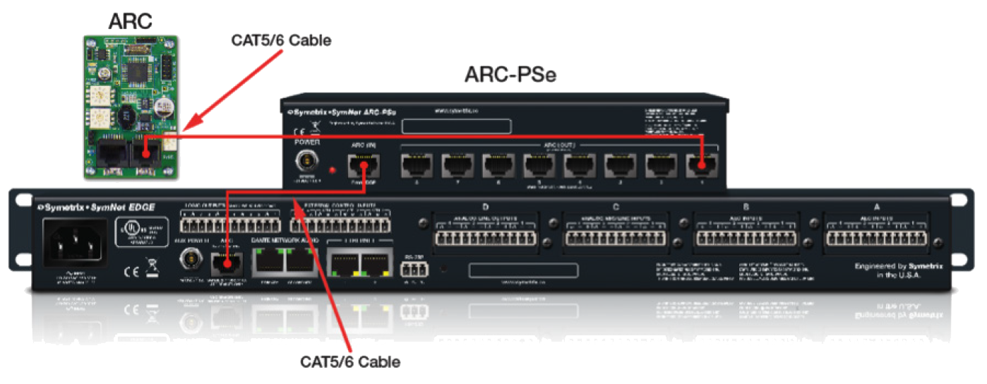
Diagram: Multiple ARC-PSe Connected to One DSP
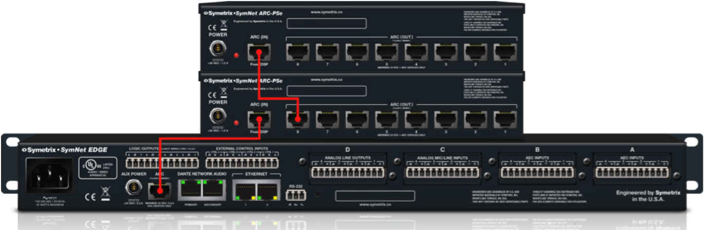
Diagram: ARC-PSe and ARC-2e (remotely), *note cable distances
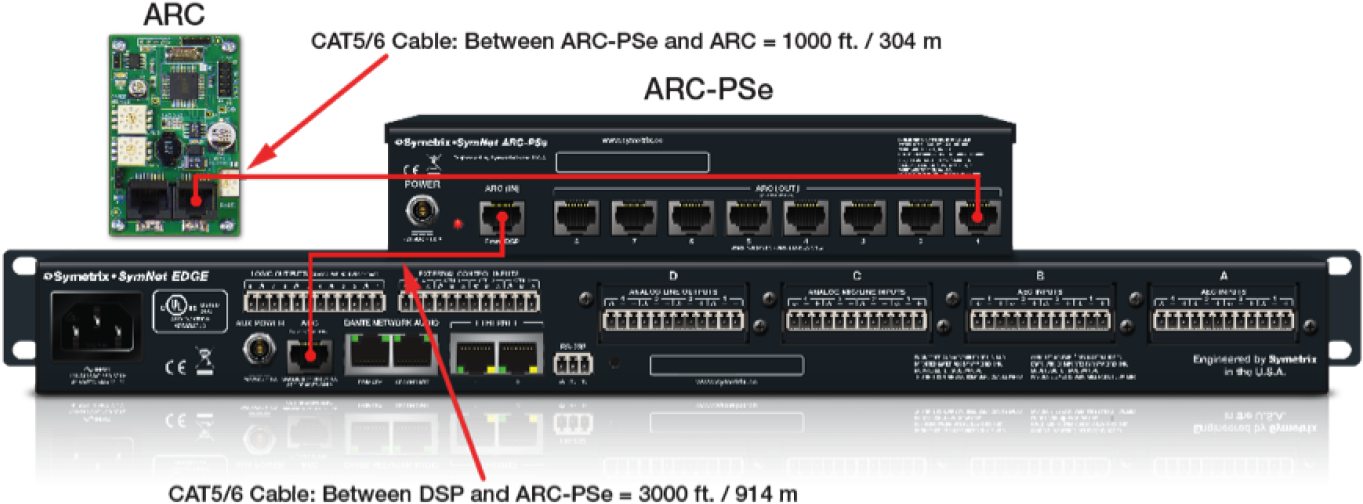
- The total length of CAT5/6 is 4000 feet / 1219 meters from the DSP to the ARC remote, which is the limitation of RS-485 data.
- Power-over-copper cannot travel 4000 feet / 1219 meters down CAT5/6 and power an ARC-2e remote.
- The ARC-PSe is mounted remotely 3000 feet / 914 meters away from the DSP.
- The ARC remote is located 1000 feet / 304 meters from the ARC-PSe.
- This setup provides plenty of power to daisy chain or power additional ARC remotes off the ARC-PSe, all of which are located between 3000-4000 feet / 914-1219 meters from the DSP.
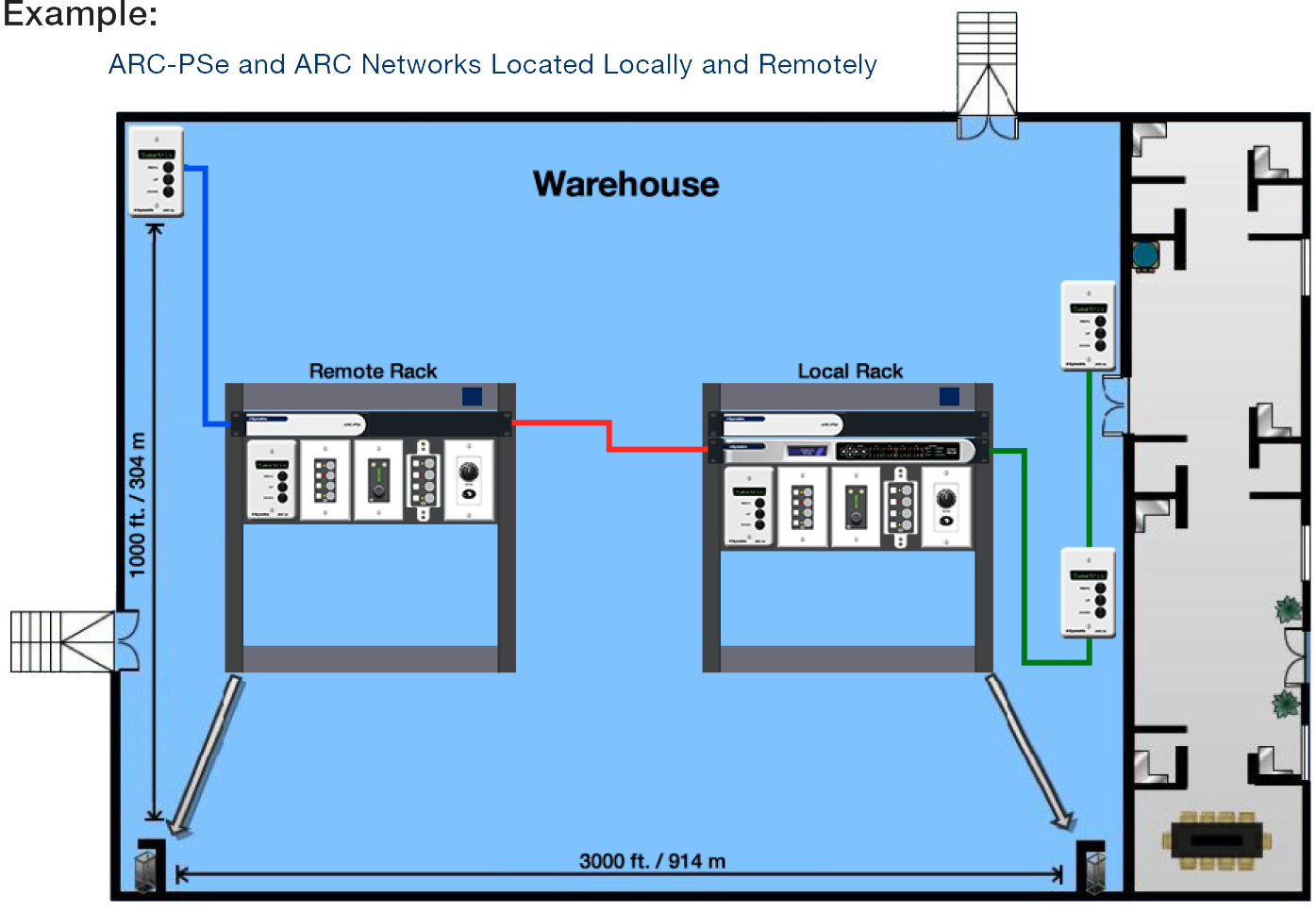
Diagram: ARC-PSe and ARC Networks Located Locally and Remotely
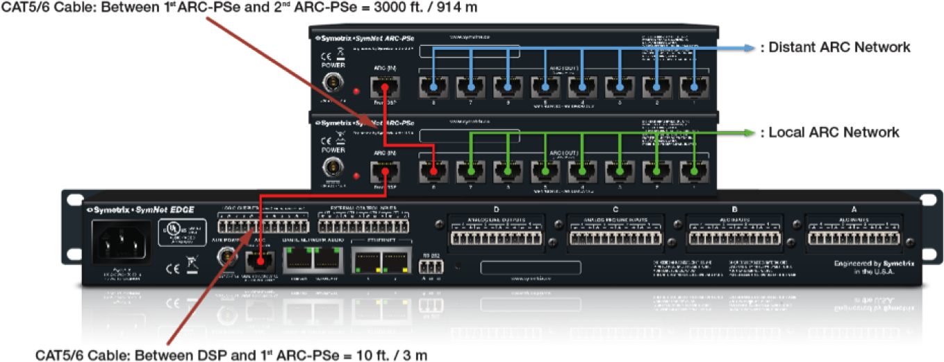
- One ARC-PSe is mounted locally in the rack with the host DSP and local ARC network. The other ARC-PSe is mounted remotely within the proximity of the distant ARC network.
- Power is not needed on the CAT5/5 cable connecting the two ARC-PSe units together. Each ARC-PSe must be powered with the included Mean Well power supply.
- ARC-PSe power is shared across all 8 ARC ports. Looking at the local ARC-PSe and the 3000 ft. / 914 m CAT5/6 cable run to the distant ARC-PSe, in order to have maximum available power for the 7 remaining ARC ports reserved for the “local ARC network”, pins 7 and 8 may be omitted from the CAT5/6 cable connecting the 1st ARC-PSe (local) to the 2nd ARC-PSe (distant).
- Any ARC on the “distant ARC network” may be no more than 990 ft / 301 m from the 2nd ARC=PSe (distant) keeping all ARC remotes located below the 4000 ft / 1219 m limitation of RS-485 data.
ARC Distance Table
The following table provides at-a-glance cable length limitations based on DC power (the table is not relevant if only RS-485 is distributed) and assumes 24 gauge CAT5/6 cabling. The lengths for multiple ARCs on a single chain assume equal distance for each cable segment between ARCs. This table is intended for quick reference only. For more detailed configuration scenarios, Symetrix has made available a Microsoft Excel spreadsheet to help system designers determine power requirements based upon cable
length, number of ARCs, and the power supply to be used. Minimum distance is based upon the ARC-2e, maximum distance is based upon the ARC-SW4e and/or ARC-K1e.
This spreadsheet can be downloaded from the Symetrix Technical Support pages here.
| ABLE SEGMENT LENGTH LIMITATIONS FOR ARC POWER OVER CAT-5 CABLE | ||||
|---|---|---|---|---|
| ARC TYPE | ||||
| Number of ARC’s on chain | ARC-3 | ARC-2e | ARC-K1e | ARC-SW4e |
| 1 | 3000’ | 3000’ | 3250’ | 3250’ |
| 2 | 1100’ | 1200’ | 3000’ | 3000’ |
| 3 | 550’ | 700’ | 1250’ | 1250’ |
| 4 | 200’ | 250’ | 400’ | 400’ |
Special note: For multiple ARCs on single chain, the listed value is assumed to be the cable length between each device. For example, a value of 600’ means 600’ between the DSP unit and the first ARC, 600’ between the first and second ARCs, etc. The total cable length will be the listed segment length multiplied by the number of ARCs on the chain.
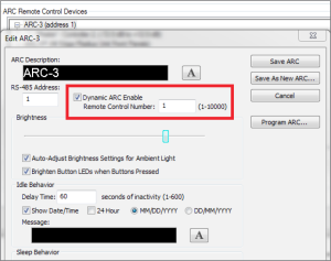
The ARC-3 wall panel delivers powerful capabilities with Dynamic Menus. Dynamic Menus allow you to enable an entire ARC or individual menus in an ARC using Controller Numbers. For example, in a room combining application, you may choose to display a separate set of menus when rooms are combined and another when uncombined. This Tech Tip will describe just a few ways Dynamic Menus can be used. Without a doubt, there are many more applications than we cover here.
In the first example, we will use a simple 4 room combine scenario. A 4 Room Automix Combiner module is used to combine inputs between rooms. A 4 Channel Gain module serves as the volume control for each room.
Each room is equipped with an ARC-3 wall panel. When all 4 rooms are separated, each room’s ARC-3 wall panel should only display the volume control for its room. When room A and B are combined, both rooms’ volume controls should appear on each room’s ARC-3’s. When all 4 rooms are combined, all 4 rooms’ volume controls would be accessible from all 4 ARC-3 wall panels.
ARC 1
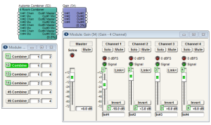
The 4 Combine buttons from the Room Combine module are assigned as menus in the ARC-3 using Controller Numbers 11, 12, 13 and 14. There are 4 gain faders from the Gain Module also added as menus in the ARC-3 using Controller Numbers 1, 2, 3 and 4.
In the ARC-3 for room A, the volume fader 1 is setup as a normal, non-dynamic menu. Volume faders 2, 3, and 4 are setup as Dynamic Menus, so they will not be accessible until room A is combined with the others.
ARC 2
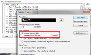
The ARC-3 Dynamic Menu uses the same Controller Numbers as the Combine buttons. The menus enable when the remote control numbers’ values are 65535, and disable when the remote control numbers’ values are 0.
The second example uses the Audio Level Detector module followed by a Threshold Detector module and Output Remote Control Number module to dynamically trigger a menu to appear in the ARC-3 when an audio signal is present. The gain fader is assigned as a menu in the ARC-3 using Controller Number 11. Gains 3 and 4 will have controller number 12 and 13.
ARC 3
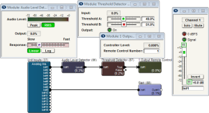
The Dynamic Menu is enabled using Controller Number 1. When audio signal is present at the Audio Level Detector module’s input, it will engage the Output Remote Control Number module turning on Controller Number 1. Set the Audio Level Detector module to RMS, with a slow response to avoid the menu coming and going between songs, for example.
ARC 3
The third example uses the 1 Button Latched module and Output Remote Control Number module to dynamically trigger all menus in the ARC-3 to appear. In this case, the Dynamic Menu is enabled using Controller Number 1 in the Edit ARC-3 Menu dialog, rather than for the individual menus. When the 1 Button Latched module is triggered, it will engage the Output Remote Control Number module turning on Controller Number 1.
ARC 4
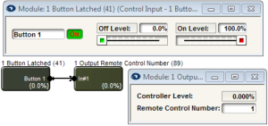
When the 1 Button Latched module is triggered, it will engage the Output Remote Control Number module turning on Controller Number 1.
ARC 5
The 1 Button Latched module’s button can be triggered in a variety of ways including the Event Scheduler to recall a preset, a physical latched button connected to an External Control Input on the rear of the DSP, or any other third party control system connected via RS-232, or UDP/IP and TCP/IP over Ethernet.
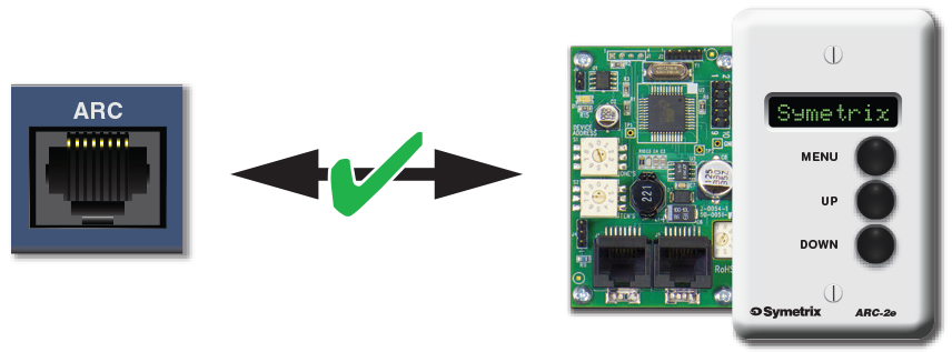
The ARC-2e is a menu-driven adaptive remote control for Symetrix DSPs. Featuring a more simplified design for enhanced reliability and robustness, the ARC-2e succeeds the ARC, ARC-2, and ARC-2i. This tech tip will review how to properly wire an ARC-2e.
General Wiring Guidelines
Most Symetrix DSPs can wire directly to a ARC-2e using a straight-through CAT5 cable.
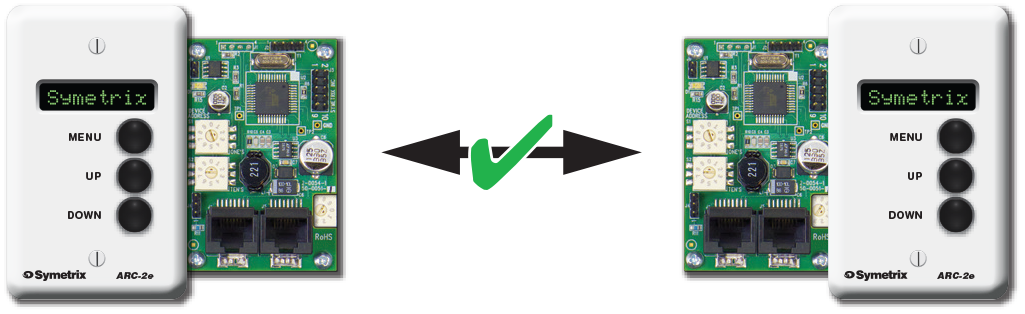
Multiple ARCs can be daisy-chained together. Download the ARC Power Calculator at www.symetrix.co to calculate distance limitations.
Wiring to a Symetrix DSP With No ARC Port
If using the ARC-2e with a Symetrix DSP that does not have an ARC port (8×8 DSP, for example), it will be necessary to connect the appropriate pins of the ARC CAT5 cable to the RS-485 port on the DSP and DC power supply.
- Terminate a CAT5 cable on one end with a male RJ-45 (8P8C).
- Strip remaining end and prepare connection to the following pins:
a. RS-485 ground > Pin 3
b. RS-485 data A > Pin 4
c. RS-485 data B > Pin 5
d. DC ground > Pin 6
e. DC + V > Pin 7
f. DC + V > Pin 8 (optional) - Pins 3, 4, 5 will connect to the RS-485 port on the host DSP.
- Pins 6 and 7 will connect to a DC power supply.
- Pins 1 and 2 are not used.
- RJ-45 end of CAT5 plugs into ARC-2e.
Within limitation, any subsequent ARC in the chain will receive data and power via CAT5 from the first ARC-2e.
DC Power Requirements
The ARC DC power requirements vary depending on the voltage supplied and the number of ARCs on the chain. At 15 VDC, one ARC-2e uses approximately 115 mA, while at 6 VDC it uses approximately 300 mA maximum. As the voltage goes from 15 to 6 VDC, the DC power requirement increases accordingly. Visit www.symetrix.co and download ARC Power Calculator for detailed information.