


-
Type
- Dante
- Networking
- Control
-
System Management
- Composer Management Software
- SymVue Screen Authoring
- AV-Ops Center Remote Monitoring
- ARC-WEB Control Interface Signal Processing
- D100 AVoIP DSP Server
- Radius NX AVoIP DSP
- Prism AVoIP DSP
- Edge AVoIP DSP
- DSP I/O Expansion Cards
- Jupiter DSP
- Zone Mix 761 DSP I/O Connectivity
- xIO Bluetooth Endpoints
- xIO XLR Endpoints
- xIO AVoIP DSP Audio Expanders Control Systems
- T-Series Touchscreen Controllers
- W-Series Controllers
- Control Server
- xControl GPIO Expander
- ARC-Series Controllers
-
Type
- Dante
- Networking
- Control
-
System Management
- Composer Management Software
- SymVue Screen Authoring
- AV-Ops Center Remote Monitoring
- ARC-WEB Control Interface Signal Processing
- D100 AVoIP DSP Server
- Radius NX AVoIP DSP
- Prism AVoIP DSP
- Edge AVoIP DSP
- DSP I/O Expansion Cards
- Jupiter DSP
- Zone Mix 761 DSP I/O Connectivity
- xIO Bluetooth Endpoints
- xIO XLR Endpoints
- xIO AVoIP DSP Audio Expanders Control Systems
- T-Series Touchscreen Controllers
- W-Series Controllers
- Control Server
- xControl GPIO Expander
- ARC-Series Controllers
Edge AVoIP DSP Tech Tips
This tech tip will explain how to properly integrate the External Control Inputs of Symetrix DSP units (Radius NX, Prism, Edge, xControl, Jupiter, Zone Mix 761). Both the physical hardware connections and programming setup will be covered.
Each External Control Input, also known as an Analog Control Input or GPIO, can be configured in one of two modes; as a dual switch closure or a potentiometer.
Dual Switch Closure mode is most commonly used with PTT/PTM (Push To Talk/Push To Mute) buttons on microphones, for an Emergency System/fire alarm relay connection that will mute or override the audio system, and for Room Combining that use switches on moveable wall partitions. The potentiometer mode is typically used to create an inexpensive, volume control for an input, source, zone, or output.
Zone Mix 761
Note: The Jupiter or the Zone Mix 761 supports a combination of up to 2 potentiometers or 4 switch closures.
Radius NX/Prism/Edge, xControl
Note: Edge, Prism, Radius NX, supports a combination of up to 4 potentiometers or 8 switch closures. xControl supports a combination of up to 8 potentiometers or 16 contact closures.
Using standard shielded twisted pair terminated with a terminal block on one end, External Control Inputs may be freely assigned to parameters in the Symetrix DSP hardware. The operational mode (switch closure vs. potentiometer) must first be configured while on-line or off-line using the Configure External Control Inputs dialog. While on-line with the DSP using the Symetrix software, a potentiometer can be calibrated for maximum travel or scaled as described later in this document.
Typical Control Switch Wiring
Note: +V(OUT)=A, INPUT=B
Typical Control Potentiometer Wiring
Configuring External Control Inputs in a Jupiter or Zone Mix 761:
Example 1: Switch Closure
This example will step through the setup of an Emergency System fire alarm mute in the Zone Mix 761 where the fire alarm relay connects to External Control Input 1A. The process is virtually identical for the Jupiter software/hardware.
First, make the physical connections using the above picture as a guide. Then, once the Zone Mix 761 software is online with the hardware, launch the External Controller Wizard. It should be noted that configuring the External Control Inputs on a Jupiter or Zone Mix 761 is straight forward since the External Controller Wizard simplifies the process.
Choose Add New External Controller, select Switch or Control Voltage and then click Next.
Now give the switch a descriptive name based on where in the venue it is located or based on what function it will provide. For example, the name could be as simple as “Switch” or as descriptive as “Fire Alarm relay”. Select the “Emergency” option for the Switch Function and click Next.
On the next page choose the desired function that will trigger based on the state of the input connection provided by the emergency fire alarm system. The two options are: Mute All Outputs or Route Input 3 to Specified Outputs at a Pre-Determined Volume Level. Select the appropriate function and click Next.
For an Emergency Fire Alarm Mute select the “Mute All Outputs” option and click Next.
On the next page, remember to select the correct physical External Control Input that the emergency system relay will connect to. This example uses Switch Closure 1A.
Once the correct input is selected, click Next.
Now, select the emergency route logic based upon how the Emergency relay functions. For reference, the software presents a few practical examples: Normally Open/Active Low and Normally Closed/Active High. Click Finish to close the External Controller Wizard or Next to return to the first page and setup another ARC remote.
Example 2: Potentiometer
This example will step through the setup of a potentiometer in the Zone Mix 761 where the RC-3 connects to the External Control Input 1. The process is virtually identical for the Jupiter software/hardware. Once connected, you can launch the External Controller Wizard and add it to your configuration.
Choose Add New External Controller, select Potentiometer (RC-3) and then click Next.
The RC-3 can control any of the twelve input volumes, the two program volumes per zone, the six zone volumes, the six output volumes, or sets of linked volumes. The particular gain stage the RC-3 will control is selected with the Parameter drop-down menu.
It may be a good idea to give the RC-3 a descriptive name based on where in the venue it is located or based on what function it will provide, especially if both External Control Inputs have a potentiometer or RC-3 connected. Click Next when done.
Select the appropriate External Control Input and click Next.
On the calibrate page, the range of the controller fader can be restricted or scaled by typing the value in Upper and Lower Limits. When finished, click Next.
In this step, calibrate the potentiometer to the 761’s External Control Input to ensure the full travel of the pot is utilized. The Zone Mix 761 software must be on-line for the calibration function to work. Rotate the pot fully counterclockwise (CCW) and click the Set Minimum Position button. Now, rotate the pot fully clockwise (CW) and click the Set Maximum Position button. Once completed, click Next and the software will return to the External Controller Wizard’s opening screen. Continue to add controllers or edit existing
ones if needed. If finished, click the Finish button to exit the External Controller Wizard.
Configuring External Control Inputs in Radius/Prism/Edge, or xControl:
Example 1: Switch Closure
This example will step through the setup of an Emergency System fire alarm
mute for a system using Composer software, where the fire alarm relay output connects to External Control Input 1A on an xControl. The process is identical for setup and assigning External Control Inputs on an Edge, Radius or Radius AEC.
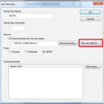
After making the physical connections, while in Schematic Edit Mode, configure the External Control Inputs by right-clicking on the unit in Design View and select “Configure External Control Inputs…”:
Remember to select “Dual Switch Closure for the input the Fire Alarm relay connects to.
Now that the External Control Inputs are configured, here is one example of control logic programming for an emergency mute/unmute function in Composer 2.0 software.
Note: Alternative logic programming examples are located at the end of this section.
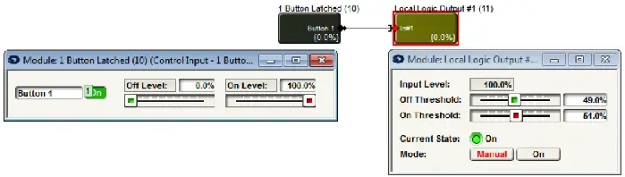
Double click the “1 Button Latched” module to open its user interface. Then assign the selected Analog Control Input to the “On’ button by right-clicking directly on the “On” button and selecting “Set Up Remote Control.”
Click the drop down arrow under Remote control device and select “Remote Analog Input – ‘xControl’” to assign an External Control Input from the xControl. For assigning an External Control Input from an Edge or Radius choose the “Local Analog Input –“Radius12x8-9” or whatever “Remote Analog Input” is appropriate.
Click the drop down arrow under Select Analog Control and choose the switch input that matches the physical wiring on the External Control Input. This example uses Switch 1A. Select OK when finished.
Once the External Control Input is assigned to a fader or button an A1 “Highlighted Assigned Control Indicator” appears super imposed on the “On” button.
Note 1: Alt+M or Tools->Super Impose Assigned Controllers must be checked.
Note 2: If the system mute performance is inverted set the Off Level to 100% and On Level to 0.0%.
Double click the “2 Input Logic” module and select “OR”. When the button is triggered, it will set the output signal to True or False when the button is On or Off, respectively.
Double click the “Preset Trigger 1” module and assign Preset #999. Composer 2.0 automatically creates Preset#999 to mute the hardware without affecting the individual output mute states. This will mute all hardware when the latched button is triggered by the fire alarm relay.
Double click the “Preset Trigger 2” module and assign Preset #1000. Composer 2.0 automatically creates Preset#1000 to unmute the hardware without affecting the individual output mutes states. This will unmute all hardware when the fire alarm relay is reset.
Note: In the Preset Manager for Composer 2.0 Preset #999 and #1000 are pre-configured for the emergency mute/unmute function, equivalent to the F2 button in Composer. 999 = Mute All Hardware. #1000 = Unmute All Hardware.
Alternative Methods:
In this example an “Inverter” module is used in place of the “2 Input Logic” module and will perform the same function as the “False” output of the 2 Input Logic (11) module from the previous example.
Here, a Super Module from Tools->Super-Module Library Manager is used for the Emergency System Mute.
Once completed, Push the file to the system.
Example 2: Potentiometer
This example will step through the setup of a potentiometer in the system using Composer 2.0 software, where the RC-3 connects to the External Control Input 1on an xControl. The process is identical for setup and assigning External Control Inputs on an Edge, Prism, or Radius.
Note: In potentiometer mode, A is the +V output and B is the voltage input.
After making the physical connection, configure the External Control Inputs by right-clicking on the unit in Design View and select “Configure External Control Inputs…”:
To configure the input for use with a potentiometer, select the appropriate input tab, and then select the “Pot – Connect a variable voltage input (0-5V)” radio button. Select “OK” when finished.
Pot Calibration:
Note: SymNet Composer must be connected to the DSP hardware with the input configured as a “Pot” in order to calibrate the input. The potentiometer must be physically wired to the External Control Input as well.
Calibrating the External Control Input determines the way the 0-5V potentiometer affects Composer parameters. There are two separate areas that can be altered:
- Compensation for pots that don’t get all the way down to 0V or all the way up to 5V. This could happen because of characteristics of the pot itself, or resistance in the connection between the pot and the unit, especially with long wire runs. This is referred to as Calibrating Pot
Range below. - Limiting the range of parameters controlled by an analog input. This is referred to as Calibrating Control Range or scaling the range.
This setting should match the control input of the pot being calibrated. If a pot is connected and the settings are correct, turning the pot should move the small indicator along the Current input position line. The value of the pot (0-255) is also updated to show the current level generated by the pot. Zero represents GND or 0V, 255 represents 5V, and the range is linear.
Calibrating Pot Range:
To compensate for a pot that does not cause its assigned fader in software to travel the entire range when the physical pot is turned to is lowest and highest position, make sure the pot is connected to the one of the 8 External Control Inputs and the correct input tab is selected in the Config External Control Inputs Window of Composer 2.0. Turn the pot to its minimum value (usually all the way counterclockwise). Click the “Set Minimum Position” button. Next, turn the pot to its maximum value (usually all the way clockwise). Click the “Set Maximum Position” button.
Note: These settings can be used to compensate for a reverse-wired pot. To reset the calibration, click the Reset Min/Max Positions and they will be returned to their defaults.
Calibrating Control Range:
It may be desirable to limit the end user range of a potentiometer connected to an External Control Input and its effect on a gain stage. For example, if a pot is controlling a volume fader, it may be preferred to limit the fader range the end user can access from -30dB to 0dB rather than the full -72dB to +12dB range allowed in the software.
To limit the upper range of a control, enter a value less than 100% for the maximum level. To limit the lower range of a control, enter a value greater than 0% for the minimum level. When set to 100% and 0%, the control is allowed to travel the entire range shown in the Composer GUI. Other values reduce this range accordingly. Some experimentation may be required to find the percentage values that limit a range appropriate the current application. As an example, for a fader with ranges -72db to +12db, 84% is equal to 0dB.
Important Notes:
By setting the minimum value to a number larger than the maximum value, it is possible to reverse the operation of the pot or compensate for a reverse-wired pot. To reset the calibration, enter 100% for the maximum level and 0% for the minimum level.
If it is desired to reset all analog calibration data for a unit, use the Erase Memory command found under Hardware->Upgrade Firmware. Select only Analog Calibration Settings and hit ERASE.
All settings made using this dialog box are stored in the hardware, not in the site file. Changes made take effect immediately without the need to download the entire site.
Assigning a Parameter:
Right-click directly on the parameter and select “Set Up Remote Control.”
Click the drop down arrow under Remote control device and select “Remote Analog Input – ‘xControl’” to assign an External Control Input from the xControl. For assigning an External Control Input from an Edge or Radius choose the “Local Analog Input –“Radius12x8-9” or whatever “Remote Analog Input” is
appropriate.
Click the drop down arrow under Select Analog Control and choose the pot that matches the physical wiring on the External Control Input. Select OK when finished.
Once the External Control Input is assigned to a fader a P1 “Highlighted Assigned Control Indicator” appears super imposed on the GUI. Note: Alt+M or Tools->Super Impose Assigned Controllers must be checked.
Once completed, Push the file to the system.
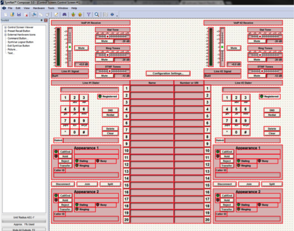
The purpose of this Tech Tip is to provide information on creating SymVue Dialer Control Screens for both the 2 Line Analog Telephone Interface Card and 2 Line VoIP Interface Card. Step by step instructions will be given on how to create the Control Screens and export them to SymVue.
SymVue is a real-time user control panel application that displays Control Screens exported from Composer functioning as a multiuser, multi-point control environment for Symetrix systems.
SymVue runs on any Windows XP or newer compatible device, including touch screen enabled PCs and tablets. The computer communicates directly with Symetrix hardware over a network connection. The desired user control interface is created in Composer as a Control Screen then exported to one or many Windows devices for tailored operation of the Symetrix system.
The Input Modules for both the 2 Line Analog Telephone Interface Card (ATI) and 2 Line VoIP Interface Cards can be exported to Control Screens. These Control Screens can be used to provide remote control interfaces (Dialers) for the ATI and/ or VoIP cards without the need or use of complicated 3rd party control systems. SymVue Dialers can be custom tailored to perform any or all of the functionality of the ATI and VoIP modules. These functions can include, but are limited to:
- Detect and answer incoming calls
- DTMF tone dialing
- Speed-dialing (edit and recall)
- Redial
- Do not disturb
- Caller ID
- Call transfer
- Call hold
- Call reject
- Local three-way audio conferencing
- Conferencing and splitting of call appearances
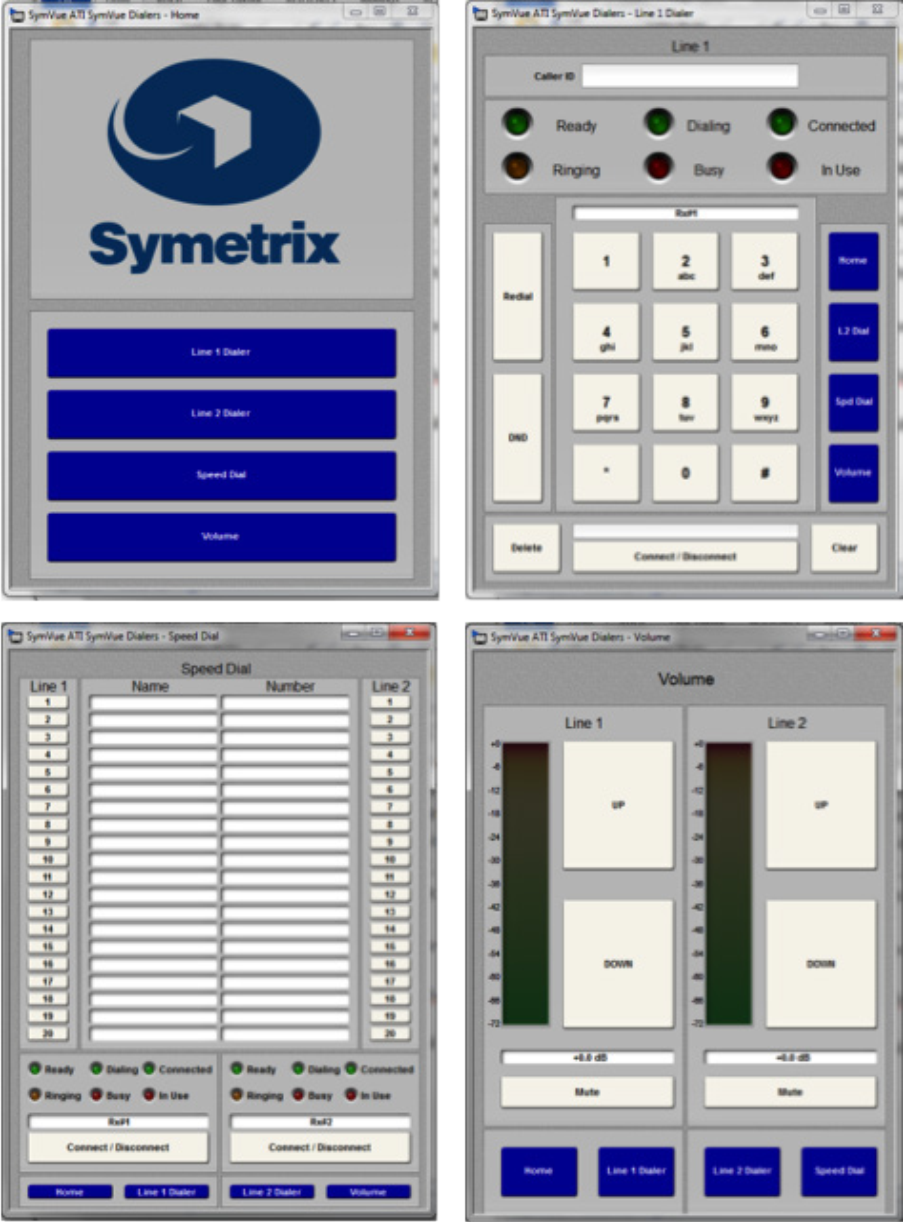
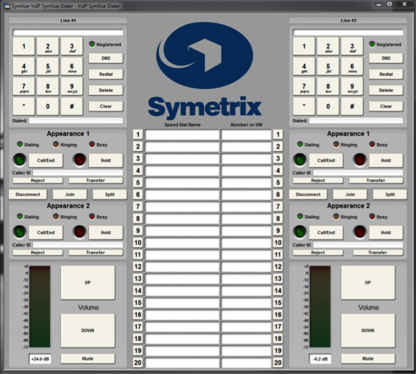
Here are some examples of the different styles of Dialers that can be created:
Instructions
1 Make sure the ATI or VoIP Interface Card has been properly installed into the Radius AEC or Edge Hardware.
install
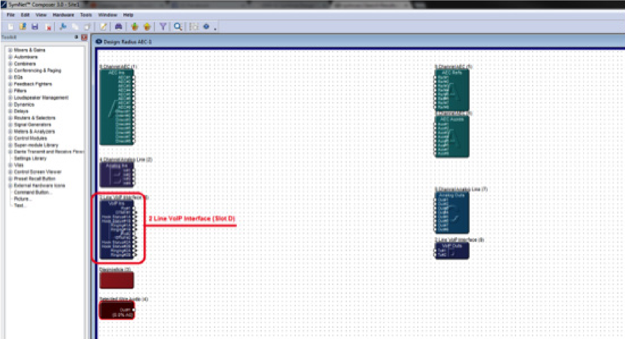
Once the card has been properly installed, the Input Modules will appear on the Design View screen of the site file.
Note: The Input Module will reflect the card slot location (A, B, C, or D). The SymVue Dialer being created will be linked to that specific card slot.
Note: SymVue Dialers can be created without having the ATI or VoIP card installed. Simply right-click the Radius or Edge in the Site View screen of the site file and select “Configure I/O Cards”. Then select the correct card for the specific card slot.
2, Double click and open the Input Module for the ATI or VoIP Interface.
3. Right-click on an open section of the module and select “Copy Entire Layout to Control Screen”.
4. Select “New Control Screen”, unless a Control Screen has already been created and it is being added onto.
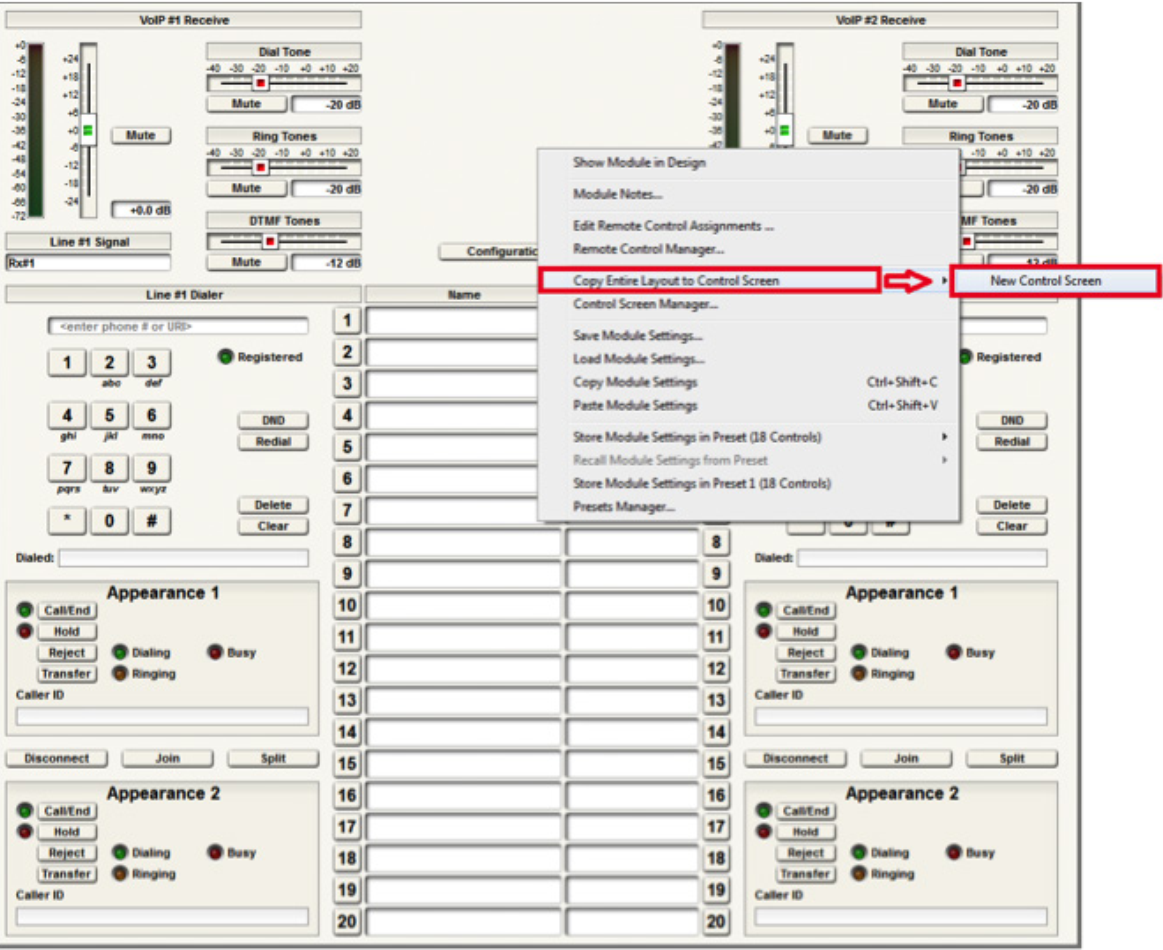
Note: individual pieces can be selected by right-clicking on the desired piece (i.e. button or fader)
The pre-built example SymVue Dialer has been tailored to use buttons instead of faders for volume control. A “2 Button Momentary” module is used connected to a “Button Ramp” Super Module (available in Super Module Tools folder). The Super Module is then connected to “Output Control Number” modules. The control numbers used by the “Output Control Number” modules are assigned to the volume fader. The “On” buttons for the “2 Button Momentary” module are copied to the control screen.
5. The functions of the Input Module have now been copied to the Control Screen and can now be tailored for specific look and operation.
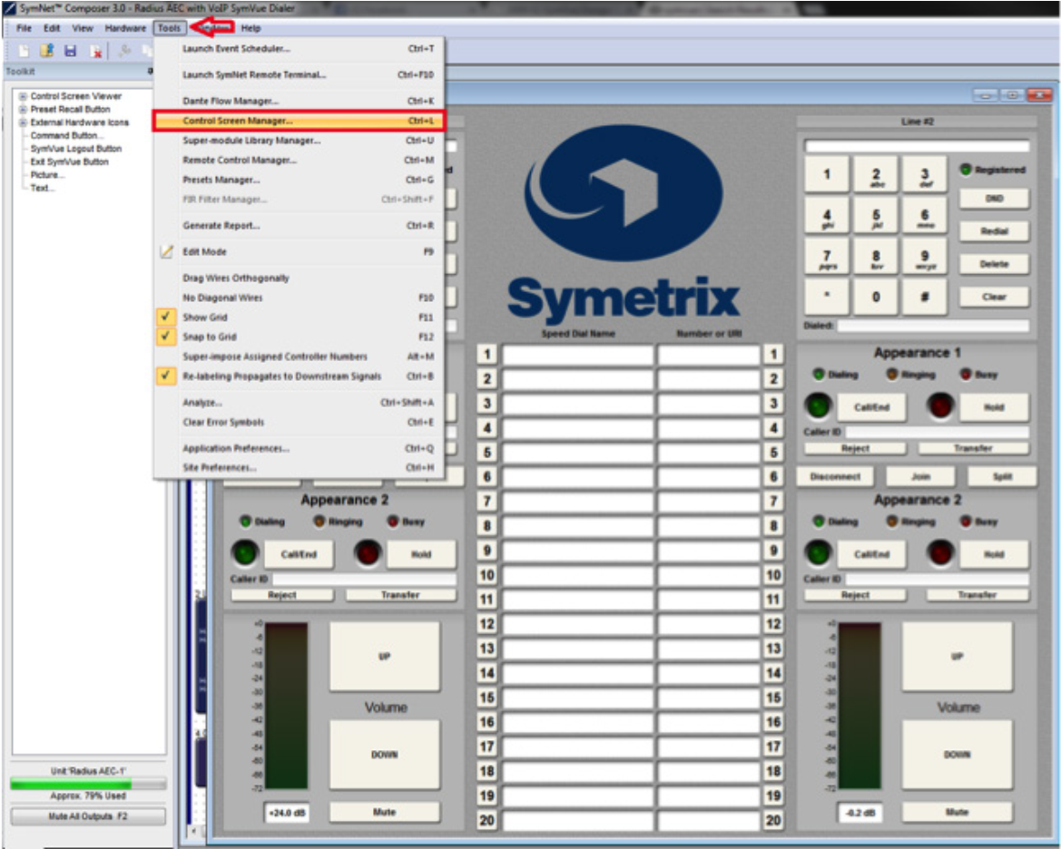
export
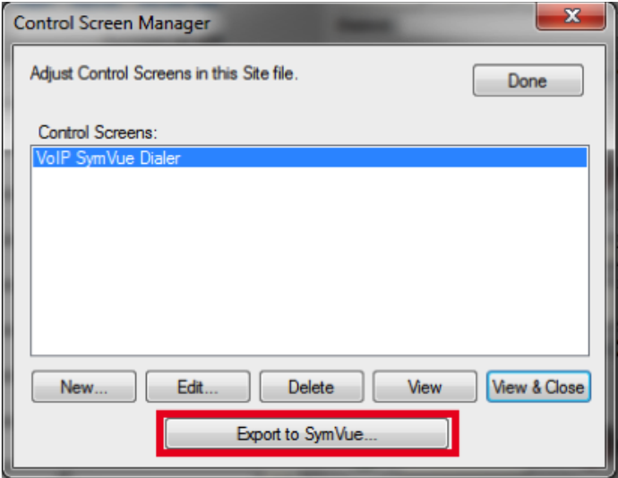
6. Once the Control Screens have been created go to Tools>Control Screen
Manager and export the Control Screens to SymVue.
For additional information on creating SymVue Control Screens click here.
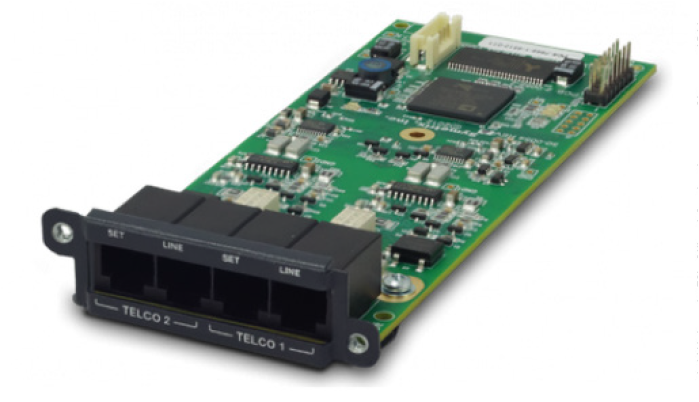
The 2 Line Analog Telephone Interface Card integrates a complete set of PSTN telephony functions into Symetrix conferencing systems. This card provides two analog telephone interface inputs to an EDGE or Radius NX with standard PSTN telephony functions. Up to four of these cards may be installed in a single EDGE for up to eight channels of local input, or one card may be installed into a single Radius NX for up to two channels of local input. Levels, mutes, inversions and formats are controllable via Composer software.
ATI 1
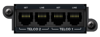
Audio inputs are accessed via rear panel RJ11 (6P6C) connectors. A variety of control options including PSTN telephones, SymVue, and third-party control devices allow intuitive end-user operation and design management. The 2 Line Analog Telephone Interface Card is suitable for a multitude of applications including conferencing, paging, remote monitoring, and broadcast.
Features
- Integrates analog telephone lines into Symetrix conferencing systems. Use up to four cards per Edge, one per Radius NX.
- Standard PSTN telephony functions include:
- Detect and answer incoming calls
- DTMF tone dialing
- Speed-dialing
- Redial
- Do not disturb
- DTMF decoding
- Caller ID reception
- Call progress detection
- Continuous line status and fault monitoring
- Standard RJ11 ports with parallel “set” connections per line for a physical handset, dialer, or ADA compliant visual or audible device connection.
- Field swappable by certified technicians.
- Also suitable for typical audio applications such as paging, broadcast feeds, and remote system monitoring.
Dialers
Standalone dialers can be used in conjunction with the “Set” port on the ATI card for an extremely cost effective solution for end user control. These dialers can be used to provide telephony features such as dialing, redial, onhook / offhook, etc. Listed are a few examples of standalone dialers.
- Accutone T3 Professional Telephone Dialer
- Luminous LH-8001D – Phone Dialer
- Revolabs Tabletop Dialer for Fusion Wireless Microphone System
External controllers (ie, Crestron Pro2) can also be used to control the telephony interface over network (TCP/IP and UDP/IP) control; it does also support serial (RS-232) control. For more information on programming, refer to the Tech Tip for “Crestron Symetrix Dialer Example.”
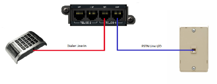
Connecting to the ATI card
- Connect the “Telco 1 – Line” port to the local PSTN wall jack using a standard telephone cord terminated with RJ11 connectors. Optionally, connect a standard analog telephone, dialer, audible and/or visual ringing device, to the “Telco 1 – Set” port of the ATI card. Repeat instructions for “Telco 2” port use.
ATI 2
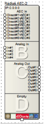
2. Open Composer and drag an Edge or Radius NX into the configuration. For this example, a Radius NX was used.
ATI 3
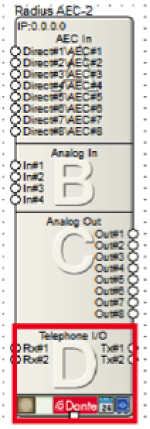
3. Make sure that the bottom box shows “Telephone I/O” with “Rx#1”, “Rx#2” and “Tx#1”, “Tx#2.”
ATI 4
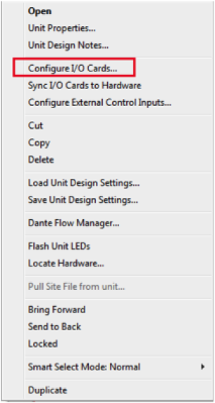
4. If the box does not show “Telephone I/O”, right click and select “Configure I/O Cards…”
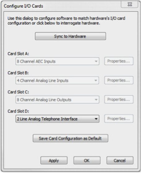
5. Select “2 Line Analog Telephone Interface” for Card Slot D, and then click OK.
Note: When setting up an Edge make sure each card slot matches the cards installed into the unit. Each card slot has the following options: No Card Installed, 2 Channel Analog Mic / Line Inputs, 4 Channel Analog Line Outputs, 4 Channel Digital Inputs, 4 Channel Digital Outputs, 4 Channel AEC Inputs, and 2 Line Analog Telephone Interface.
ATI 5
Once the I/O card is added, open the Site File and begin the design.
Overview
With the Two-Line Analog Telephone Interface Card, Symetrix offers a complete conferencing solution within the Composer architecture. The Two-Line Analog Telephone Interface Card (ATI card) is compatible with both the Edge and Radius NX. The Edge is a card-based DSP with four card slots available, allowing it to support up to four ATI cards per unit. Radius NX has one optional card slot available, allowing it to support one ATI card per unit.
Conferencing applications are the most common designs in which the ATI card will be specified; however, there are several other applications that may benefit from the addition of the ATI card and the functionality it provides.
These additional ATI card applications include, but are not limited to:
- Telephone Paging
- Remote System Monitoring
- System Soft Reset
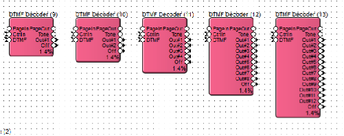
All three of these applications are accomplished by using the ATI card in conjunction with the DTMF Decoder module provided in the Composer Toolkit under ‘Conferencing & Paging’. The DTMF Decoder Module provides a way to trigger logic events in a system using custom DTMF tone sequences from a telephone. Most often the DTMF Decoder will be used to trigger a preset, but it can also be used to trigger any logic function, such as a bell, message player, logic output, etc. In Composer there are 1, 2, 4, 8, and 12 output versions of the DTMF Decoder. When more than 12 DTMF sequences are needed, multiple DTMF Decoders can be used in parallel.
Telephone Paging
line 1
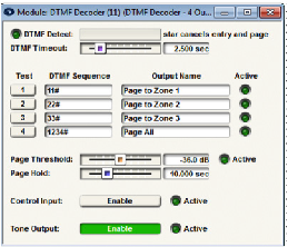
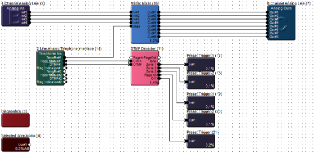
In a paging application, the DTMF Decoder can trigger routing presets based upon DTMF sequences. In the provided example, the DTMF Decoder is set to trigger individual zone paging to zones 1 through 3, with a “Page All” preset also included on the DTMF Decoder output #4. The ATI card Telephone Ins module DTMF output connects to the DTMF input on the DTMF Decoder.
The Hook Status output of the ATI card connects to the CtrlIn (control input) of the DTMF Decoder, which will monitor when the call is ended and then trigger the Off output of the DTMF Decoder. The Off output triggers a preset that will reset the routing matrix so that no zone selections are active between each page.
Remote System Monitoring
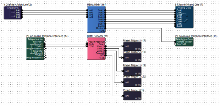
Similar to triggering a routing preset for paging applications, a routing preset could be triggered to allow remote monitoring of a system by an event manager, concierge, or integrator under a service contract. This would allow for remotely calling a venue and actively listening in on a current meeting or event. Additionally this solution could be used by a technician for hearing a problem first hand, such as noise or distortion from a speaker or mic that an end user is experiencing, potentially eliminating a long drive to a venue when a problem is related to user error.
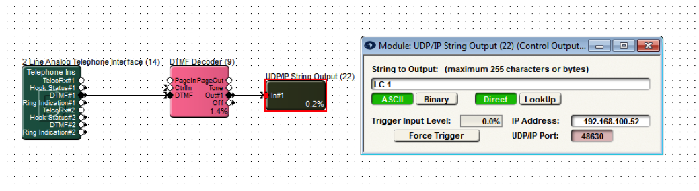
System Soft Reset
Many times an audio system is tuned by an integrator or acoustician and the end result is an amazing sounding system. While ideally these tuned parameters would be static so that the audio system will always sounds its best, the end user will need to be able to reconfigure routing, control gains, and mutes, not to mention any other esoteric control functions the end user requires.
As such, sometimes a system ends up in a state, after weeks or months of end user adjustments, in which the end user perceives that the audio system “no longer sounds as good as it once did.” With an ATI card included with the system, some very basic logic can be used to set the entire system back to the tuned “default state” of all parameters without power cycling the hardware. This is known as a “soft reset.”
The programming is simple. In a Composer Site File, an ATI Telephone Ins DTMF output connects to a DTMF Decoder. The DTMF Decoder module output connects to a UDP/IP String Output Module or RS-232 String Output module that is used to send a “soft reset” command back to itself. With the UDP/IP String Output Module the command is simply sent to the DSP’s IP address on port 48630. When using a RS-232 String Output module, simply connect the RS-232 phoenix connecter Tx to Rx, such that the command is sent by a DSP to itself. The command to be sent to the DSP for a soft reset is “LC 1” which stands for Load Configuration 1 and will cause the DSP to load the archived Site File. The archived site file is the state of all parameters exactly where they were when the last “Push” was performed from Composer.
Applies to Radius NX, Edge, Prism xControl, Jupiter, and Zone Mix 761
This tech tip will explain how to properly integrate the Logic Outputs of the above DSP units into your installation. Typically these outputs would be utilized in a couple of ways – driving LEDs in order to give visual feedback to an end user, or controlling an external relay for switching other equipment, such as a projector screen or rack of other equipment. In order to do this is as seamlessly as possible, it is first necessary to know some basic facts.
First, each of these logic outputs is the open collector of a switching transistor that has its emitter tied to ground. What does this mean to you? These are not dry contacts that are simply open or closed. When the transistor is inactive, 5V is present at the logic output. When the transistor is activated, the 5V is shunted to ground through the transistor’s emitter, which results in 0V at the logic output.
Here are the specs for the logic outputs that we’ll be referring to in this tech tip:
- The logic output is pulled high (5V) when inactive.
- The logic output goes low (0V) when active.
- The maximum logic output source current is 10mA.
- The maximum external power supply voltage is 24 VDC.
- The maximum external power supply current sinking is 50mA.
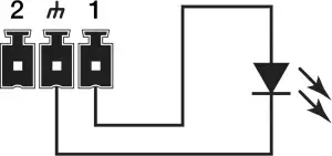
How to Drive an LED
With a max output current of 10mA, it is possible to drive an LED directly from the logic output without needing a current-limiting resistor (there is an internal 500 ohm resistor). This of course depends on the forward voltage and forward current of the LED you choose (check the datasheet for your LED). In this case, simply connect as below:
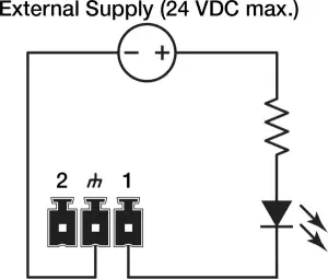
If you have an LED that requires a higher voltage/current demand, an external power supply will be needed. As stated above, the max external power supply voltage is 24 VDC with 50 mA sinking current. Hook it up as below:
You can calculate the resistor’s value by using Ohm’s law:
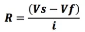
Vs = Supply Voltage
Vf = LED forward voltage drop
I = LED forward current (in Amps)
Round up your value to the nearest standard resistor value.
Note: Various styles of LEDs (from standard through-hole to panel-mounted) in a seemingly endless variety of values are readily available. The best approach would be to identify your needs in terms of LED type, then use the extensive search functions of sites like Digikey.com or Mouser.com to see what is available.
Driving Relays
There are two types of relays we’ll work with to control external devices, the most common being a non latching mechanical relay. Taking into consideration the 10 mA output current of the logic outputs, this type of relay will typically need to have its coil driven by an external power supply. As noted earlier, the external supply should not exceed 24 VDC, while the relay coil current should not exceed 50 mA. A relay such as the Omron G5LE-1A4 DC12 should do nicely.
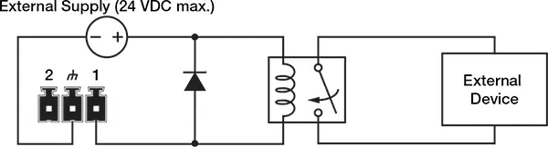
Take note of the flyback diode placed in parallel across the relay coil. This provides a path for discharge current to flow when the coil is switched off. Without this diode, there is the risk of damaging or destroying the internal transistor of the Symetrix device. Think of a flyback diode as the cheapest equipment insurance policy you’ll find anywhere. Use a 1N4004 or equivalent.
Another relay option would be to use a Solid State Relay (SSR), which typically has a lower current requirement for activation. Most installers use mechanical relays, but some of the advantages of SSRs are worth noting:
- Low turn-on requirements. There is no inductive coil to drive in an SSR. Instead there is an internal LED that toggles the relay, which typically requires very little current to turn on. If you choose one that requires less than 10 mA to activate, there is no need for the external power supply that you might need to power a mechanical relay coil.
- No mechanical wear-and-tear, arcing, or contact bouncing.
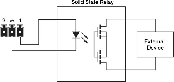
For a general use SSR, try a Panasonic AQV252G (max load voltage 60 VDC/VAC, max current of 2.5 A).
Triggering the Logic Outputs in SymNet Composer (Radius, Edge and xControl)
As a basic example, we’ll set up a logic output to be toggled on and off by an external device such as a Crestron or AMX controller.
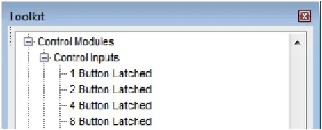
1 In Composer’s Design View, drag in a single Latched Button from the Toolkit.
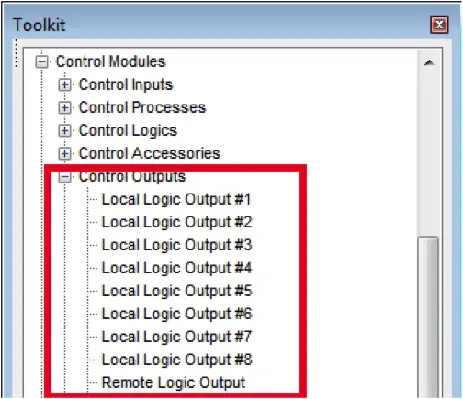
2. Drag in a “Local Logic Output #1” Module from the Toolkit. To use an xControl’s logic outputs, select the “Remote Logic Output” module instead.
3. Wire the output of the latched button module to the input of the logic output module.
4. Right-click the “On” Button in the latched button module and click “Set Up to Remote Control.”
5. Select “Generic Controller Number Assignment” from the drop-down menu. Either keep the “Auto-assign controller number” checkbox selected, or un-check to type in your own controller number. Click OK, then push the site file to hardware.
6. You will now be able to control the button with your external controller.
- To enable the button, send this command to the DSP: CS <CONTROLLER NUMBER> 65535 <CR>
- To disable the button: CS <CONTROLLER NUMBER> 0 <CR>
Be sure to download the Composer Control Protocol from our website for full command details.
Triggering Logic Outputs for Jupiter and Zone Mix 761
Use the “External Controller Wizard” in the software to walk through programming your logic outputs.
- Setting up analog volume knobs and switches.
- LED clipping indicators for visual feedback.
- Triggering a power sequencer at 6AM every day.
These are just a few of the many things that can be accomplished with Symetrix hardware. All of our DSP units provide some degree of General-Purpose Input/Output (GPIO) via the External Control Inputs and Logic Outputs.
This document provides a side-by-side comparison of the GPIO counts for each piece of current Symetrix hardware, so you can spec the right gear for the job. Keep in mind that each individual External Control Input can either be configured to use a 10K potentiometer as its input, or two switches.
| Hardware | External Control Inputs | Logic Outputs |
| D100 | 0 | 0 |
| Edge | 8 switches / 4 pots | 8 |
| Radius NX 12×8 | 8 switches / 4 pots | 8 |
| Radius NX 4×4 | 4 switches / 2 pots | 4 |
| Prism | ||
| xControl | 16 switches / 8 pots | 16 |
| Jupiter | 4 switches / 2 pots | 4 |
| Zone Mix 761 | 4 switches / 2 pots | 4 |
For full details and walkthroughs on integrating GPIO, see the below Tech Tips:
This article will demonstrate Composer control logic for automatically hanging up a call if no DTMF signal is received within a period of time. The logic is designed to function with both VoIP and ATI option cards for Radius NX and Edge.
Logic Demonstration
How It Works
There are five key modules used in this design. This section will go through them one by one:
- The Flip-Flop module keeps track of whether or not a DTMF signal has been received from the far end. Normally, the “Set” input would be wired to the “DTMF#1” output of the 2 Line VoIP Interface module, but here it is simulated by a 1 Button Momentary module. The “Reset” input is wired to the “Hook Status#1A” output of the 2 Line VoIP Interface module, with an inverter in between. This will reset the Flip-Flop after the call ends.
- The 2 Input Logic module outputs “True” when the call is active and a DTMF signal has not been received from the caller. Otherwise, the module outputs “False”. The “In#1” input is wired to the “NOT Q” output of the Flip-Flop. The “In#2” input is wired to the “Hook Status#1A” output of the 2 Line VoIP Interface module. The logic type of this module should be set to “AND”.
- The Ramp Processor module takes in the control signal from the “True” output of the 2 Input Logic module and outputs a control signal that ramps up over a specified period of time. Here, it is set to 10 seconds, but this can be set to any desired value. This represents the amount of time the caller will have to enter a DTMF signal before the call automatically hangs up.
- The Threshold Detector module takes in the ramping control signal from the Ramp Processor module, but only outputs a control signal once the ramping control signal reaches 100%. In order to do this, the “Threshold A” value must be set to “100%”.
- The 1 Output Remote Control Number module takes in the control signal from the “True” output of the Threshold Detector module and outputs a high (100%) control signal to Remote Control Number 1. Note that the “Call/End” button in the 2 Line VoIP Interface module has been set up to Remote Control Number 1. This button will be activated when the 1 Output Remote Control Number sends its control signal, ending the call.
video
Troubleshooting VoIP issues by performing a data packet capture
For VoIP problems that may be experienced when deploying a Symetrix VoIP Interface Card, a useful tool for troubleshooting problems is a network protocol analyzer. Problems are likely taking place on the network or SIP PBX outside of the VoIP Interface Card and a network protocol analyzer allows examination of the communication between the VoIP Interface Card and the VoIP PBX. In most cases, a very short capture of network traffic is enough information for a Symetrix engineer to scrutinize and begin diagnosing a problem. To perform the capture, a computer with a wired Ethernet connection, Wireshark network protocol analyzer software and a managed Ethernet switch with port mirroring are needed.
Installing Wireshark
Start by going to http://www.wireshark.org and clicking on the DOWNLOAD link. Please click the download appropriate for your operating system. Complete the installation process.
Using Wireshark to capture packets
To capture network traffic between the Symetrix VoIP Interface Card and the SIP PBX, a secondary managed Ethernet switch that supports port mirroring will be used. If a secondary managed Ethernet switch is not available, then arrange for a port to be mirrored on the main Ethernet switch that connects back to the SIP PBX.
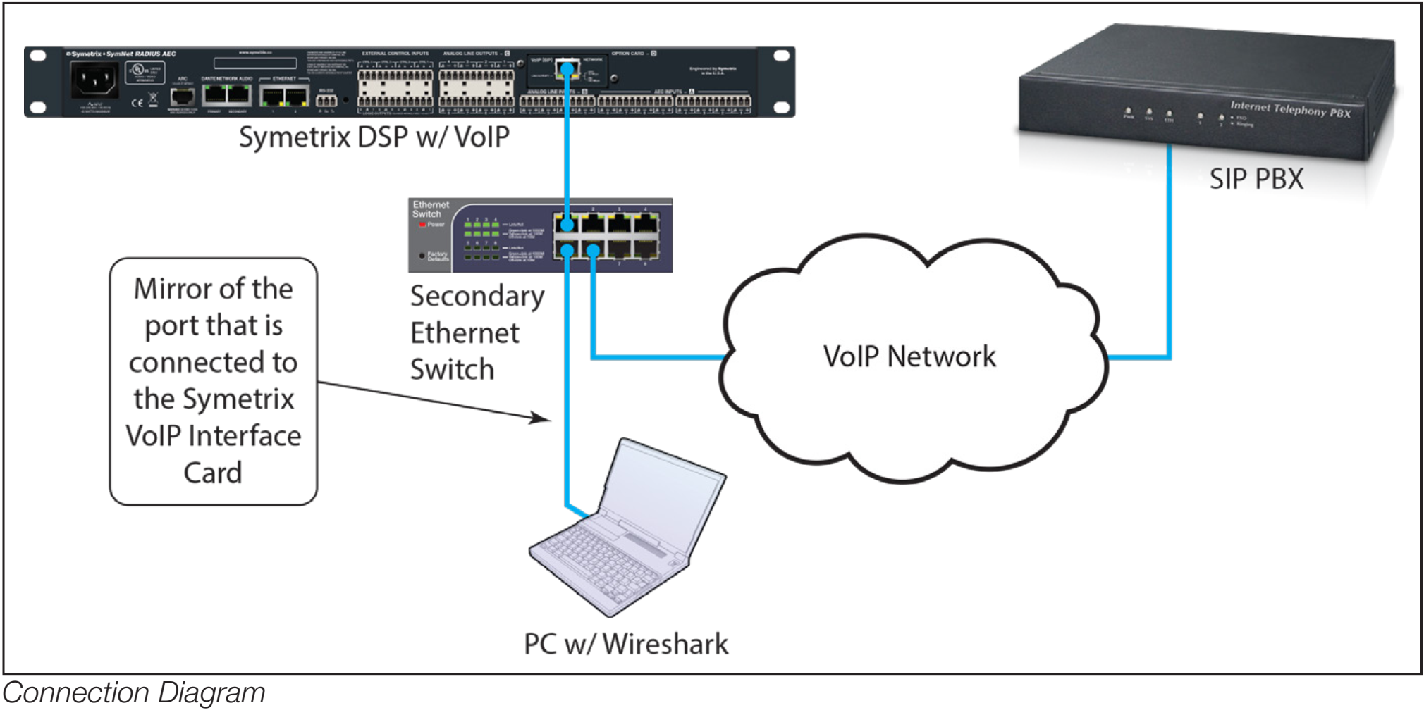
- First setup port mirroring on the managed switch. Port mirroring setup is performed differently for different makes of switches and directions on setting up a mirrored port should be directed to the switch manufacturer
- Connect the computer running Wireshark to the port to which traffic is mirrored.
- Connect the Symetrix VoIP Interface Card to the port of the switch from which traffic is mirrored.
- Connect a port from the main Ethernet switch that connects back to the SIP server to the Ethernet switch being used for the port mirroring.
Proceed to “Capture a Wireshark Trace”
There are just a few more steps to complete before we begin recording network
traffic with Wireshark.
- We recommend closing all other applications at this time, especially any connections to the network. This helps to keep the enormous number of packets recorded to a minimum and makes it simpler to read the traffic.
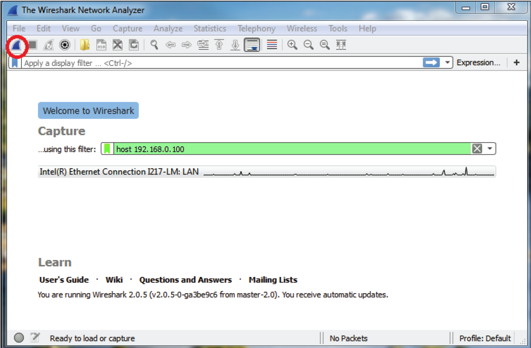
- Wireshark needs to know where to look for packet traffic. At the main window of the Wireshark Network Analyzer, click Capture on the Menu Bar and select Interfaces from the list of options. (Capture > Options: Interface drop-down, promiscuous mode).
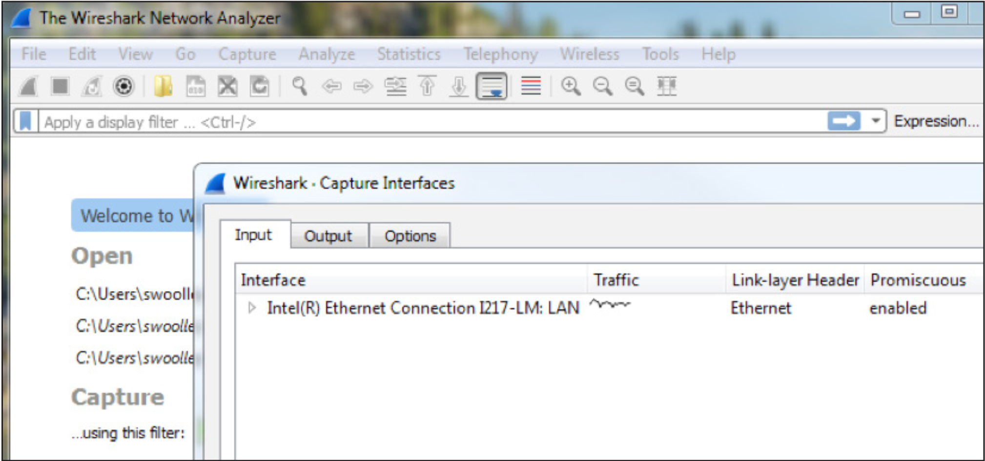
Select the Ethernet card the PC uses as its information access.
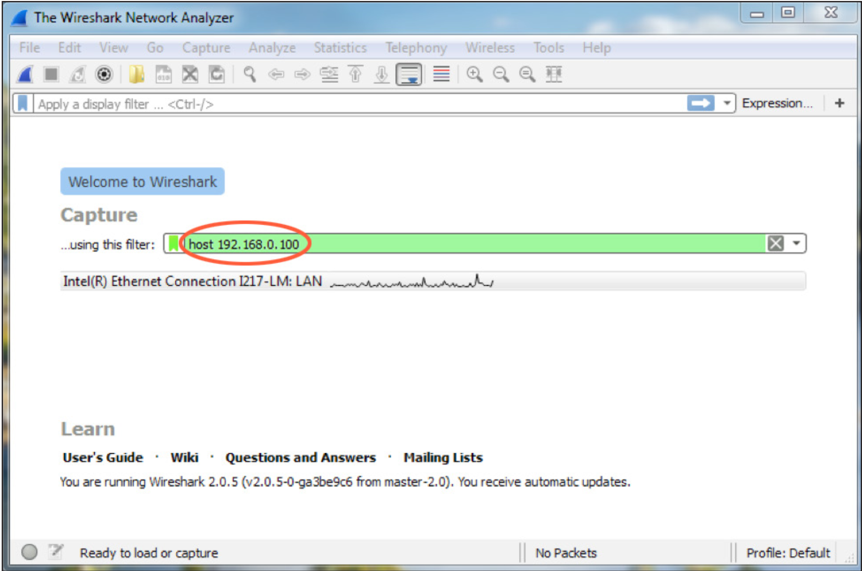
3. Set the capture filter to only capture network traffic to and from the VoIP
Interface Card by typing “host” followed by the IP address of the VoIP Interface
Card in the “Capture …using this filter:” box.
4. Power down the Symetrix DSP which hosts the VoIP Interface Card.
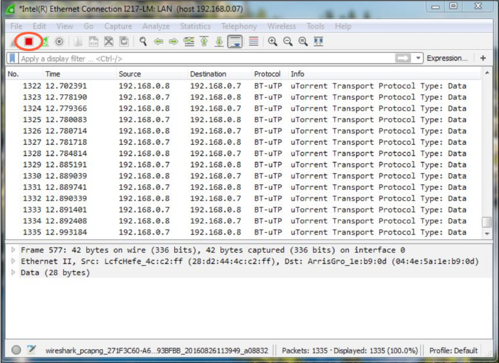
5. Start the Wireshark capture by clicking the Start Capture icon in the Tool Bar
6. Next, power up the DSP and leave the capture running until the DSP has completed boot-up. This will cause the VoIP interface to start the registration process with the SIP PBX.
7. Once the DSP has completed booting, check in Composer and verify if the VoIP interface is registered.
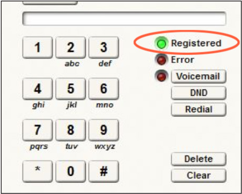
If it is not, stop the capture by clicking the Stop Icon on the Wireshark Tool Bar.
If it is registered, while the capture is still running make a call from the Symetrix DSP to another extension and answer the call at the other extension if it rings. Then hang up the call at the extension. Next, call the Symetrix DSP from another extension and answer the call if it rings. Depending on the problem, additional calls may need to be made for troubleshooting.
8. Once the capture is completed, stop the capture by clicking the Stop Icon on
the Wireshark Tool Bar.
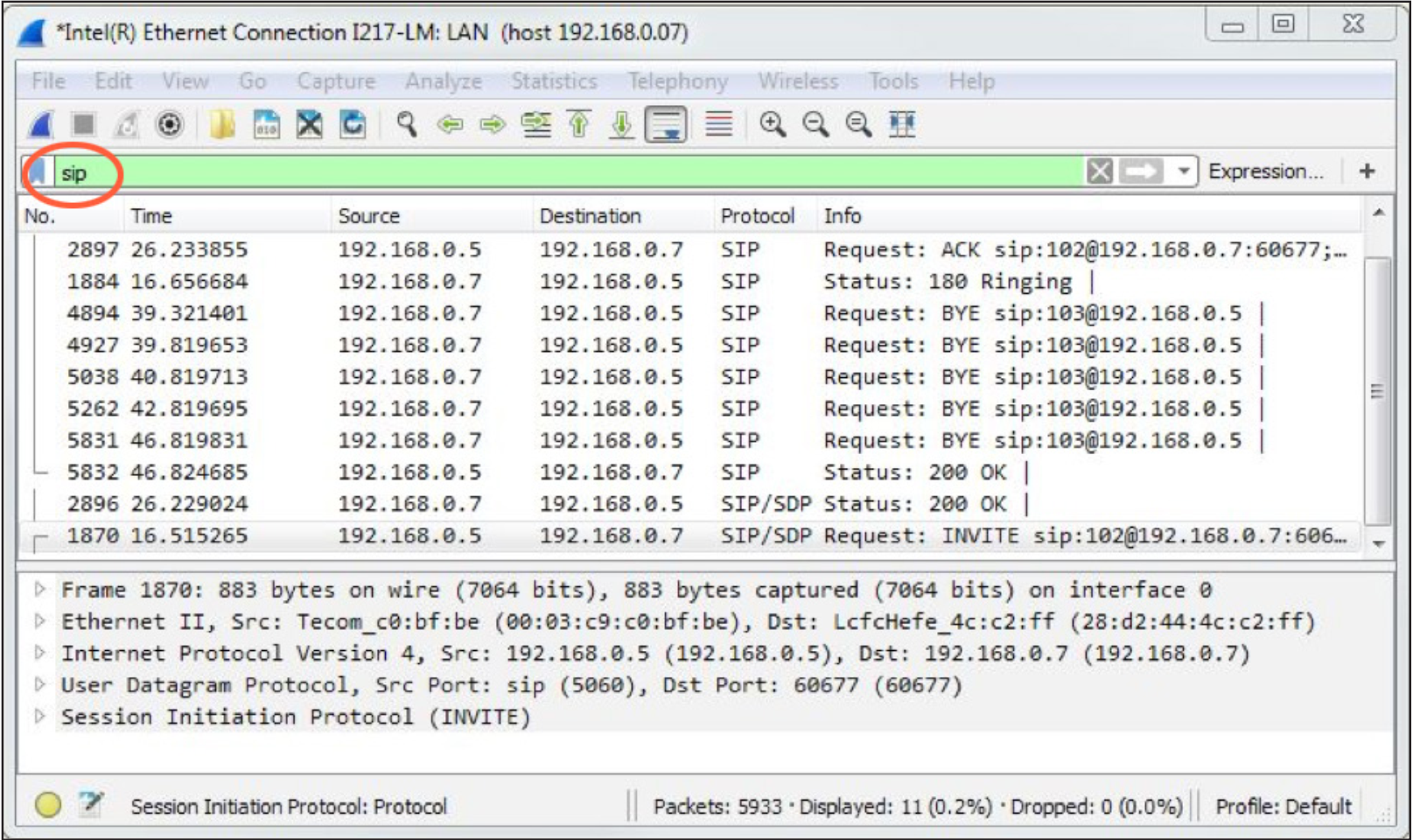
9. Wireshark’s top window should be populating with packet information. Verify
that the data needed has been captured by typing the word “sip” (lowercase) in
the display filter box.
If there are no SIP messages shown, the capture was not correctly performed and will need to be redone once correct capture settings have been set.
10. Once the capture has been stopped, save the information in a file that can be e-mailed to Symetrix. Click on File in the Menu Bar and choose Save from the list of options. When the Save File As dialogue window appears, leave all fields at their default settings (Packet Range information and File Type) and enter a memorable name for the .pcap file. It might be useful to include your company
name or some other unique identifier for association. In addition, make sure you know where this file is being saved so that you can retrieve it for e-mail attachment (the desktop is always easy to find, for example).
That’s it. We are now in a much better position to help you solve any technical difficulties you may be experiencing concerning VoIP troubles related to your Symetrix hardware
The purpose of this Tech Tip is to provide information and instruction on using AES67 with Symetrix Dante-enabled DSPs. The AES67 standard provides interoperability between different forms of AoIP (Audio over IP). AES67 is not a networking solution in and of itself, but rather a group of interoperability specifications for connecting media streams. AES67 is supported by various IP-based audio networking systems such as Dante, Ravenna, Livewire and Q-LAN.
Because Dante supports AES67, this allows Symetrix Dante-enabled DSPs to receive and transmit audio with other IP-based audio networking systems, Q-LAN as an example. When using Symetrix Dante enabled DSPs with AES67, there a few key points to keep in mind:
- Symetrix Dante-enabled DSPs are compatible with AES67, but are not AES67 specific hardware.
- AES67 stream assignments are handled by the receiving device
- AES67 streams will only appear as a transmitter in Dante Controller.
- AES67 transmit streams from a Symetrix Dante-enabled DSP will NOT be assignable in Dante controller.
- Here is a link to set up AES67 receive flows with Q-SYS
- AES67 is capable of unicast and multicast communication, however Dante’s implementation of AES67 currently only supports multicast.
- When two Dante-enabled devices are passing audio between each other they will always use Dante for the communication, regardless of AES67 streams.
- Audinate’s Ultimo chipset does not currently support AES67
- Here is a link to the AES67 standard
AES67 Receive Stream
Here are the instructions for creating AES67 receive buses, using the generic Network Receive Modules (This example uses a Radius AEC and QSC Q-SYS Core 250i)
aes 1
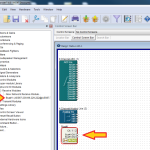
1. From the Toolkit, add a Radius AEC to the Site View page.
aes 2
2. Open the Design View page by double-clicking the Radius AEC.
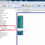
aes 3
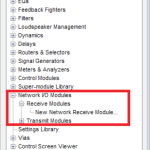
3. From the Toolkit, expand Network I/O Modules, then expand Receive Modules.
aes 4
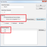
4. Double-click or drag in a New Network Receive Module.
aes 5
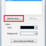
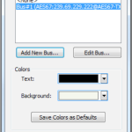
5. The Network Receive Module Properties window will open automatically. Click the button to “Add New Bus.”
aes 6
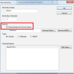
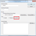
6. Change the type to AES67.
aes 7
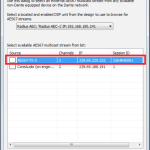
7. Click the “Browse AES67” button.
aes 8
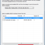
8. Select the desired AES67 multicast stream from the list.
aes 9
9. Click the “Select AES67 Stream” button.
aes 10
10. The New Bus window is now updated with the AES67 stream information (device network name and channel names).
11. The new AES67 receive bus is available in the Network Receive module Properties window.
12. Click Ok. The new receive bus has now been created.13. Push the site file and Composer will make the AES67 to Dante subscriptions.
13. Push the site file and Composer will make the AES67 to Dante subscriptions.
AES67 Transmit Stream
Here are the steps to create AES67 transmit streams:
aes 11
1. Open the site file to the Design View page.
aes 12
2. From the Toolkit, expand Network I/O Modules, then expand Transmit Modules.
aes 13
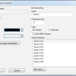
3. Add a New Network Transmit Module. The Network Transmit Module Properties window will open.
aes 14
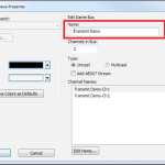
4. Edit the name of the transmit bus. Note: Naming of transmit buses is very important for organization.
aes 15
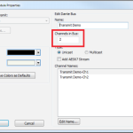
5. Select the number of channels in the transmit stream.
aes 16
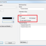
6. Select the transmit bus type.
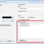
7. Name the individual transmit channels.
8. Click OK and the transmit bus will be added to the site file.
6. Select the transmit bus type.
7. Name the individual transmit channels.
8. Click OK and the transmit bus will be added to the site file.
While all Symetrix open-architecture DSPs can display their IP address on the front screen, not all of them allow that IP address to be edited right from the front panel. This guide will quickly explain how to do this.
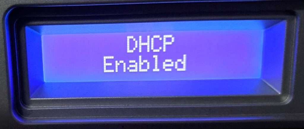
Hold the Menu/Enter button and enter the system pages. Then, using the left and right arrow keys, scroll to the page displaying the DHCP status.
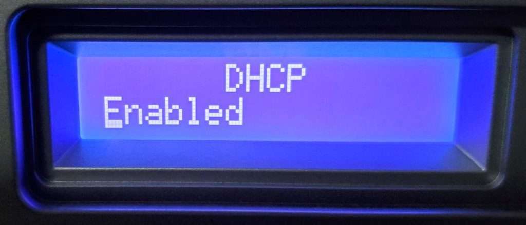
Click the Menu/Enter button, which will enable editing mode of this page, noted by the status moving to the left justification and the underscored character.
Click the Up or Down arrows to change this status to Disabled.
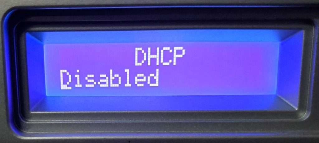
Then click the Menu/Enter button again to confirm the change.
Next, scroll to the page showing the unit’s Control IP address.
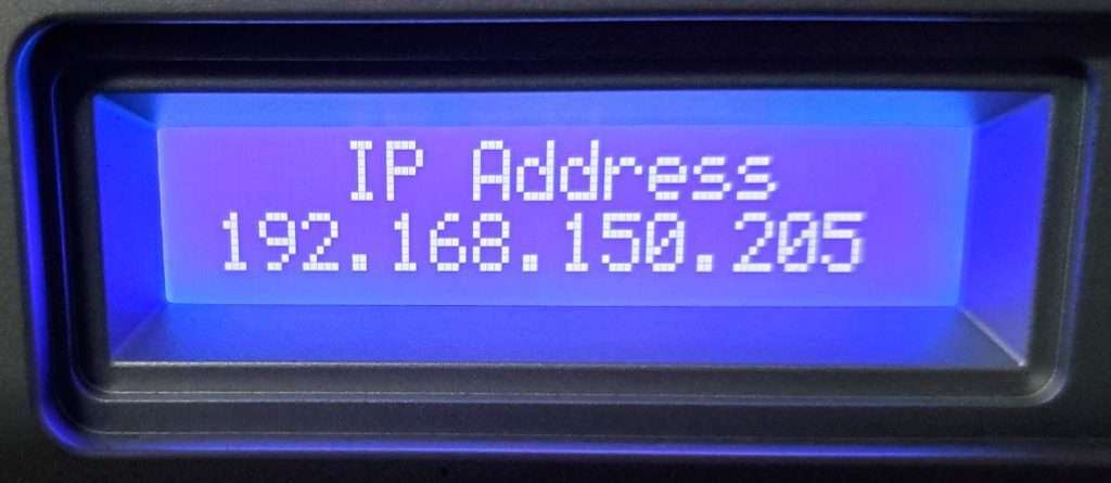
Click the Menu/Enter button to enter edit mode, noted by the underscored character.
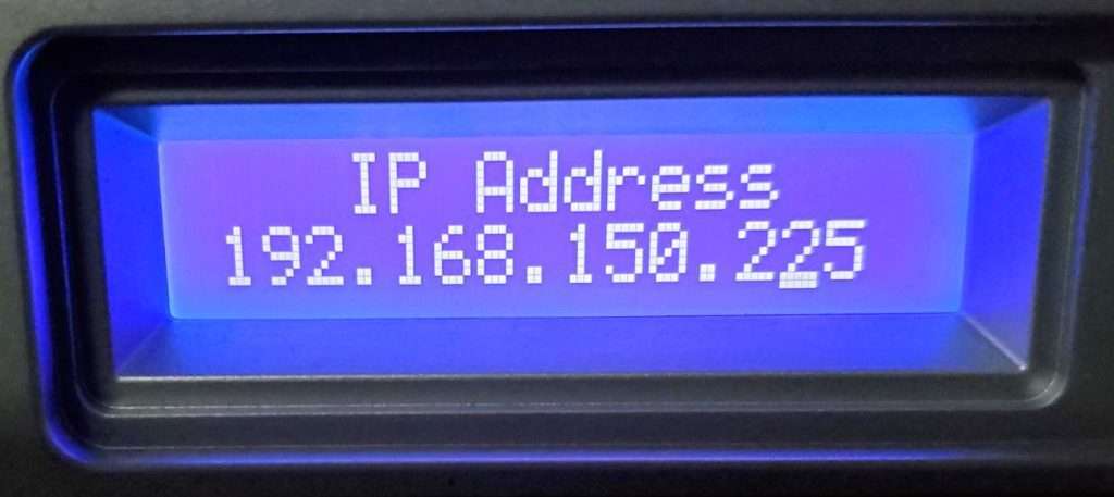
Move the edit cursor/underscore to the desired character and use the up and down arrow keys to edit. Click the Enter/Menu button again to confirm this change.
This is a general-purpose step-by-step guide for connecting to Symetrix digital signal processors and related hardware with a PC. Please note that Symetrix only recommends using Windows 10 and above. Other operating systems are not officially supported at this time.
Step 1 – Install the right software for the device
Symetrix site design software is used to connect to Symetrix devices and is available to download, install, and run for free. The required software will depend on the devices that needs to be accessed:
Composer:
Current Symetrix open-architecture DSPs all use Composer, which can be downloaded here. These include:
- D100
- Radius
- Prism
- Edge
- Solus NX
Other Symetrix hardware that can be accessed through Composer will include:
- Endpoints and expanders (xIn, xOut, and xIO devices)
- T Series touch panels
- W Series wall remotes
- Control expanders (xControl, Control Server)
Important: To avoid errors when going online with the hardware, please download the version of Composer that matches the DSP’s firmware revision number as closely as possible. This number can be found by cycling through the system pages on the front LCD panel of the DSP.
Integrator Series:
Software for Symetrix’s current Integrator Series (closed-architecture) DSPs can be downloaded here. These include:
- Jupiter
- Zone Mix 761
Legacy Hardware:
Legacy open-architecture DSPs such as 8×8 DSP, Express CobraLink, and original Solus (non-NX) require SymNet Designer. This software has been discontinued and is no longer supported by Symetrix, but the final version (10.7) can be downloaded here. Software for all other legacy products, such as Zone Mix 760, AirTools-series, and Lucid-series, is no longer available for download.
Step 2 – Make sure the PC is on the right network
Once the correct software has been downloaded, the next step is to connect the PC to the device’s control network. If a DSP is Dante-enabled, make sure not to confuse the Dante ethernet port for the control ethernet port. Configuration of these devices through the Symetrix software is always done through the control port.
By default, Symetrix devices will obtain an IP address automatically, either from a DHCP server or, if a DHCP server is not available, by obtaining a link-local (169.254.x.x) IP address. Most Composer-enabled devices will display their IP address on the front LCD panel. Cycling through the system pages on the front LCD will additionally display the subnet mask. If a device has previously been configured with a static IP address, it can be reset to DHCP by briefly pressing the device’s reset button, which is usually recessed in the housing on the back of the device.
ncpa
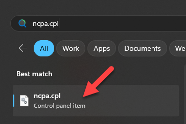
It is important that the PC’s network settings match those of the devices being used in the system. To check this, enter ‘ncpa.cpl’ in the Windows search bar to open the list of network adapters on the PC:
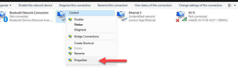
Right click the network adapter that will be used to connect to the device, select ‘Properties.
version
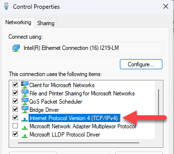
Then double click ‘Internet Protocol Version 4’:
address
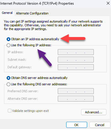
The network settings of the PC’s network adapter will display. If the Symetrix device is set to DHCP, select ‘Obtain an IP address automatically.’ Alternatively, a static IP address and custom subnet mask can be set here:
Important: Ensure that both the IP subnet and subnet mask of the network adapter match that of the device. If setting the PC to a static IP address, it must be a different/unused IP address on the network. If connected directly to the DSP with a static IP address, setting the PC to an address “right next to” the DSP usually safe. Example; if the DSP IP address is 192.168.100.50, set the PC to 192.168.100.51.
Step 3 – Locate the Symetrix hardware on the network
Once the PC is on the correct network, open the appropriate Symetrix software. The next steps will depend on the software being used.
Composer:
site
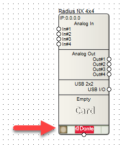
If a copy of the site file is available on the PC: Select the ‘File’ menu > Open and select it from File Explorer. In Site View, all located devices will have a checkmark in the lower left corner. If there is no checkmark present, click the empty box in the lower left corner of the device to open the Locate Hardware menu:
In the Locate Hardware menu, a list of available devices will appear. If necessary, click ‘Select Network to Search…’ to ensure that the correct network adapter is being used to scan for devices. Either double click the device in the list or highlight it and select ‘Locate to Selected Hardware’ to finish locating the device:
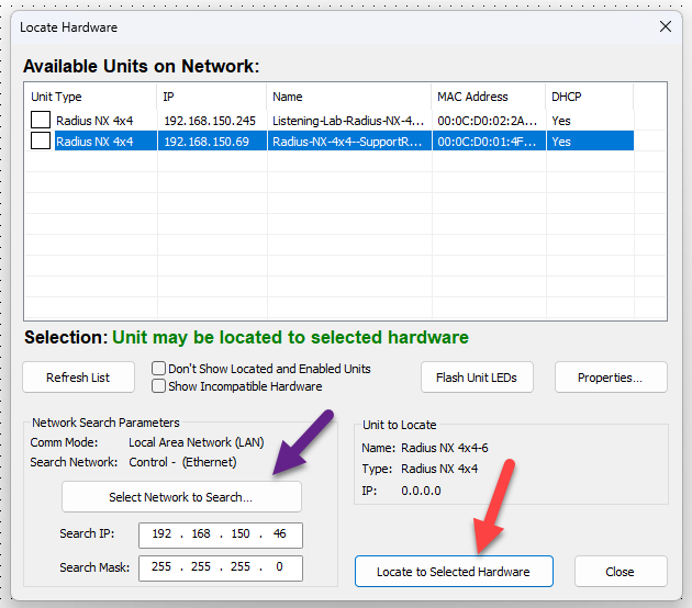
Repeat the above process for all devices in the Site View.
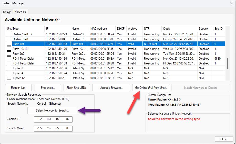
If the site file needs to be pulled from the unit:Go to the ‘Hardware’ menu > ‘System Manager’ > ‘Hardware’ tab. A list of all available units on the network will display. If needed, click “Select Network to Search…” to change the network being scanned for devices. Highlight the desired unit, then select ‘Go Online (Pull from Unit…)’:
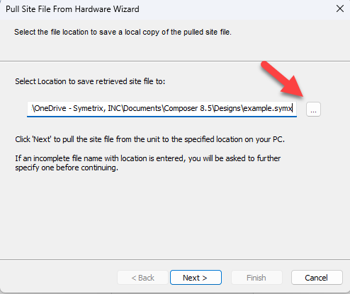
The Pull Site File From Hardware Wizard will appear. Select a location on the PC where the site file will be saved, then click ‘Next’:
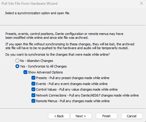
Next, select either ‘Yes – Synchronize to All Changes’ to keep any changes made to the configuration while last online with this site file, or ‘No – Abandon Changes’ to revert to the archived version of the site file. ‘Show Advanced Options’ allows for more granular control over which changes are kept when synchronizing:
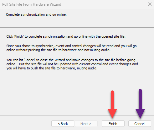
Select ‘Next’, then either select ‘Finish’ to go online with the site file as-is or select ‘Cancel’ to make changes to the site file before going online:
A note about Dante devices– Any Dante devices in the design must be located through a Symetrix DSP that has already been located:
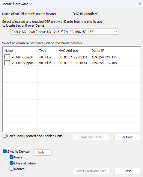
As of Composer 8.5, an xIO Updater/Configurator module may be added to the site view to configure Symetrix xIO Dante devices if a Symetrix DSP is not available. Symetrix recommends using separate networks for Dante and control.
Integrator Series:
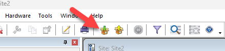
Locating an Integrator Series DSP is done in the Connection Wizard of the Jupiter or Zone Mix 761 software. This can be done either by selecting ‘Existing File on Device’ > ‘Open Connection Wizard’ from the startup menu, or by selecting the Connection Wizard icon in the top ribbon:
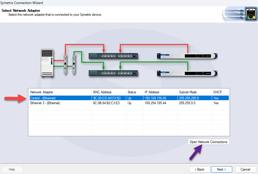
Once the Connection Wizard opens, select the option that best fits the connection type, then select ‘Next’. A list of the PC’s network adapters will appear. Select the one that is connected to the ethernet port of the device, then select ‘Next’. Select ‘Open Network Connections’ to show these network adapters in Windows Control Panel if any settings need to be changed:
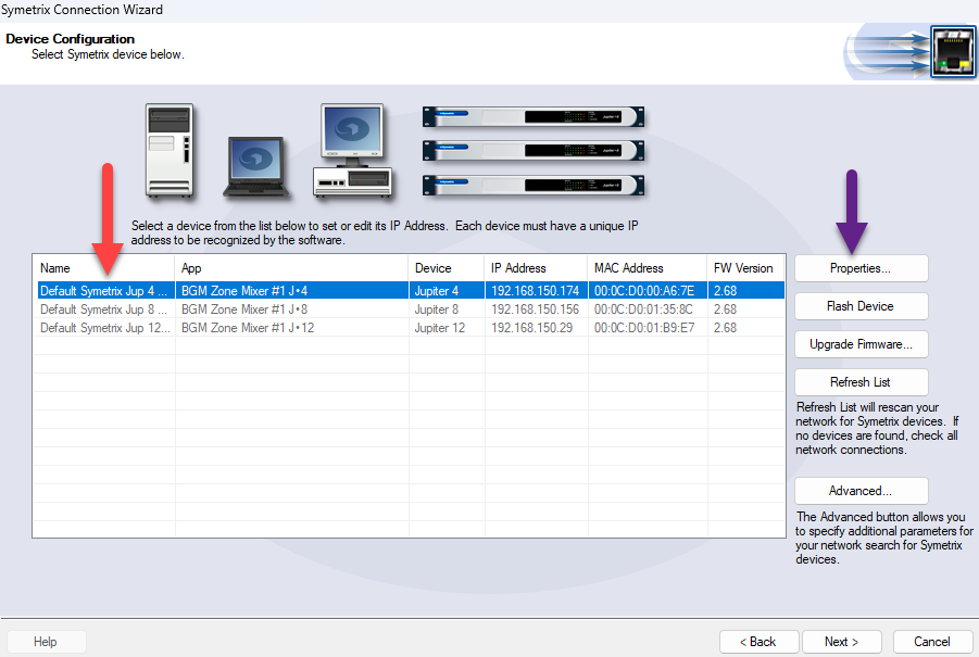
A list of devices will appear. Any devices not compatible with the current site file will be grayed out. Select the device, then select ‘Next’. Selecting the ‘Properties…’ button will allow a static IP address to be set for the device if desired:
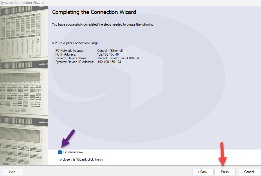
On the final screen, select ‘Finish’ to close the Connection wizard. To go online immediately, ensure the ‘Go online now’ box is checked:
Step 4 – Go online with the system
Composer:
online
Once all devices in the site file have been located, select ‘Go online (push site file to hardware)’:
Note: The icon with the yellow arrow is for pulling the site file from the located hardware. Please see the passage entitled “If the site file needs to be pulled from the unit” in the previous section for more information on pulling the site file from the hardware.
Next, the Site Preferences window will appear. These are generally advanced options that can be left alone, however if Dante routing is being managed in Dante Controller rather than in Composer, uncheck the box next to ‘Configure Network Audio.’ Click ‘OK’ to proceed:
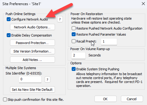
dialogue
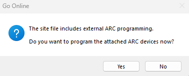
At this point, if the site file has not yet been saved to the PC, the File Explorer will appear and prompt for a filename and location to save the file to. If any ARC remotes are present in the design, a dialogue will appear and ask if all remotes should be programmed now. Regardless of whether ‘Yes’ or ‘No’ is selected here, the system will continue to push and go online:
success
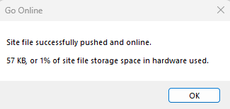
Once the site file has been successfully pushed, a success dialogue will appear. After clicking ‘OK’, the system volume will gradually ramp up unless the system mute is engaged:
Now that the system is online, parameters can be changed in real time, and signal meters will display their data. However, if any modules are moved, added, or deleted, or if any wires are changed, the system will automatically go offline. The site file must be re-pushed in order to go back online.
Important: The firmware versions of all devices in a Composer site file must match the version of Composer being used before going online with the system. If this is not the case, a message will appear prompting a firmware upgrade before the system can go online. Please refer to the Updating Firmware with Composer Tech Tip for further assistance.
Integrator Series:
After finishing the Connection Wizard, select the orange ‘Off-line’ button in the top ribbon. The drop-down arrow can be selected to choose which previously located device to go online with:
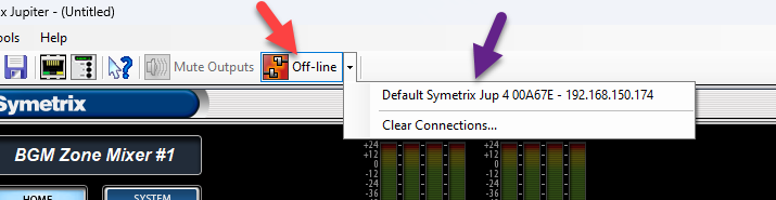
A prompt will then appear allowing the user to select whether to push the currently open configuration file to the device, or to pull the configuration file off of the device and save it to the PC.
Once the system is online, parameters can be changed in real time, and signal meters will display their data.
Integrator Series devices will operate normally with the factory firmware and should not require firmware updates to go online.
FAQs and Troubleshooting
“My device does not appear in the Locate Hardware menu.”
- Double check that the PC’s NIC and the Symetrix device are on the same network.
- Double check that the selected network in the Locate Hardware menu corresponds to the intended NIC.
- Change all octets of the IP address and subnet mask being searched for to ‘255’, uncheck the box next to ‘Don’t show located and enabled units’, and check the box next to ‘Show incompatible hardware’ in order to broaden the search as widely as possible.
- If a USB to ethernet adapter is being used with the PC, connect using a standard ethernet port instead if possible.
- Power cycle both the PC and the device.
- Re-seat the ethernet cable in both the PC and the device.
- Try a different ethernet cable.
- If the device is connected to the PC through a network switch, try a different switch port, or connect directly to the PC instead.
- If all else fails, disconnect the device from the network, reset its network settings by tapping the reset button once, then directly connect it to the PC (ensuring the PC is set to automatically obtain an IP address).
“I’m getting a ‘Failed to go online’ error message.”
- Disable Windows Defender Firewall and any third-party antivirus/firewall programs that may be blocking network traffic.
- Double check that the device firmware versions for all devices in the site file match the version of Composer being used (the first two numbers are most important).
- Power cycle both the PC and the device.
- If the device is connected to the PC through a network switch, try connecting directly instead.
- If a device cannot be located and is not needed in the site file, right click it and select ‘Disable Unit’.
“I can’t locate my Dante device.”
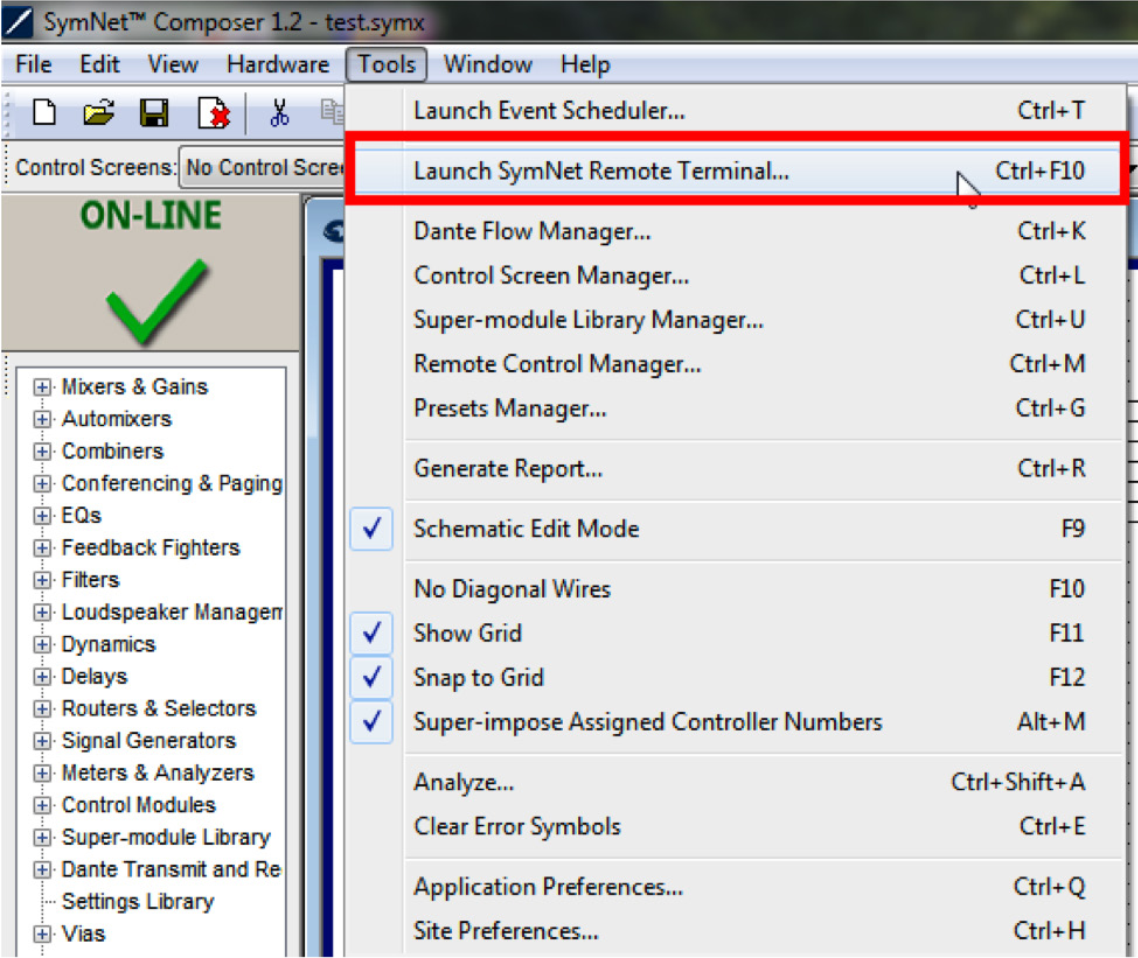
- Double check that the DSP is Dante-enabled by going to the ‘Tools’ menu > ‘Launch Remote Terminal’ > ‘Options’ menu > enable ‘Debug Mode’, then send the command info cards to the IP address of the DSP. If ‘Non-Dante Clock Card’ is displayed in the output under ‘Audio Network Card’, then the device does not have a Dante card installed. Please contact sales@symetrix.co to purchase one. If ‘No Card Present’ is displayed instead, there may be a problem with the Dante card.
- Double check that the Dante device is connected to the Dante port of the DSP.
- Connect the Device directly to the DSP’s Dante port, bypassing any network switches. If it can be located using this method, there may be a problem with the network.
- If all else fails, connect the PC to the Dante network, or directly to the Dante device, and verify that it appears in Dante Controller. If not, then there may be a problem with the Dante device, or it may be set to a static IP address outside of the Dante network.
“What does the yellow checkmark next to a device in Composer mean?”
A yellow checkmark means that the device is muted, while a green checkmark means that the device is unmuted.
This guide provides the detailed steps required to both create an account on a CUCM v9.x with the bare minimum required/recommended settings, and to register a Symetrix 2 Line VoIP Interface card to the CUCM.
Navigating to the CUCM
- Enter the IP address of the server into a browser’s address bar and press
Enter (example: 10.30.0.50) - Click on Cisco Unified Communications Manager
- Type in your Username and Password and select Login.
Preparing the CUCM
Note: : All fields marked with an ‘*’ in CUCM are required for proper setup, some of these fields are set by default
The steps to create a user account and the related phone information are described next
1) Create a Phone Security Profile
a. Select System>Security>Phone Security Profile
b. Click Add New
c. Under Phone Security Profile Type select Third-party SIP Device v(Advanced) and select Next (Basic – single line device)
i. Enter the Security Profile Name under “Name*” (Symetrix VoIP UDP, in this example)
ii. Select the desired Transport Type (UDP in this example)
iii. Check Enable Digest Authentication (we recommend using authentication credentials)
d. Click Save.
2) Create an End User
a. Select User Management>>End User
b. Click Add
i. Create User ID (Symetrix, in this example)
ii. Last Name (Inc. in this example)
iii. Digest Credentials (used for authentication) (12345 in this example)
c. Click Save
3) Create a Phone
a. Select Device>Phone
b. Click Add New
c. From Phone Type, Select Third-party SIP Device (Advanced) and then click Next
d. Device Information box
i. Enter the MAC Address of the Symetrix 2 Line VoIP Interface card, and description (optional, will default to SEP+MAC Address if left blank)
ii. Device Pool = Default
iii. Phone Button Template = Third-party SIP Device (Advanced)
Note: If only a single line registration is required, we may be able to support the Third-party SIP Device (Basic) option.
e. Protocol Specific Information box
i. Device Security Profile = Name of security profile created in step 1)
ii. SIP Profile = Standard SIP Profile
iii. Digest User = End User Created in step 2)
f. Click Save
4) Setup Directory Numbers (DN) for the device (this is the extension number)
a. Click on Line [1] – Add a new DN link on left of page
b. Directory Number Information box
i. Enter a Directory Number (311 in this example)
ii. Enter an Alerting Name (Note: ASCII Alerting Name field will auto fill when this is entered)
c. Line 1 on Device (description given previously) box (Optional)
i. Enter Display (Caller ID) (Note: ASCII Display (Caller ID) field will auto fill when this is entered)
d. Click Save
e. Click GO next to “Related Links: Configure Device (description given previously) to return to the Phone Configuration page
f. Click on Line [2] – Add a new DN link and follow steps b through e above to register the second line on the Symetrix 2 Line VoIP Interface card.
g. Click Save
Registering the Symetrix 2 Line VoIP Interface
Now that the Cisco CUCM is ready for the Symetrix 2 Line VoIP Interface card, it is time to put the appropriate CUCM credentials into the Symetrix Web Admin tool.
1) Setting up Line 1
a. Identification tab
i. Display Name (any display name you want)
ii. User Name (this will be the Directory Number for one of the lines created in CUCM, 311 in this example)
iii. Domain Name (server IP address, 10.30.0.50 in this example)
iv. Local Phone Number (This is the number which a far end would dial to call the card)
b. Server tab
i. Server Name
ii. Server Address (this is the address of the CUCM)*To set up Line 2 follow the same steps as Line 1, but the User Name will be the Directory Number created for the second line of the device in CUCM
This tech tip will walk through the necessary steps required to receive audio in an Edge, Prism, or Radius NX DSP from the Dante Virtual Soundcard running on a PC or MAC laptop.
The Dante Virtual Soundcard software allows a PC or Mac to connect to a Dante audio network. Dante Virtual Soundcard uses the Ethernet port on the computer to communicate with a network of other Dante enabled devices. No special hardware is required other than installing Dante Virtual Soundcard on a conventional PC or laptop. Audio applications use the Dante Virtual Soundcard as they would any standard ASIO or Core Audio sound card. Sending audio from your laptop to the DSP using Dante has many benefits including but not limited to: testing the Dante network, sending test tones or pink noise to the DSP outputs, and tuning the speakers with known audio content. Another application might be to play recorded content in an audio installation, such as intermission messages or sound effect playback in theaters. There are certainly many other useful applications so be creative.
What you will need:
- Composer
- Edge, Prism, or Radius NX
- Dante Controller (www.audinate.com)
- Dante Virtual Soundcard (DVSC) (www.audinate.com)
- An ASIO capable program such as Cubase, Logic, Sound Forge, Winamp
In this example Winamp will be utilized as it is a free download available on the web. From the Winamp website the ASIO Output Plugin will also need to be downloaded.
1) Open Winamp and go to Options->Preferences (Ctrl + P).
2) Next, click on Output section of “Plug-ins” and choose the “ASIO Output Plugin [out_asio.dll]” to select the ASIO driver for Winamp.
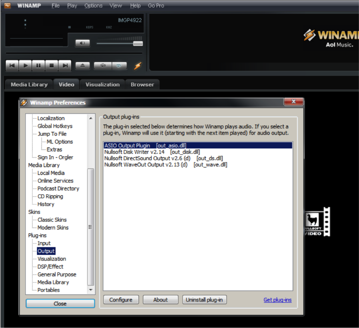
3) The Config ASIO dialog will pop up, and the Dante Virtual Soundcard will need to be selected.
ra 1
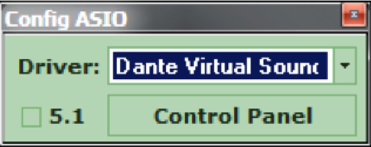
3) The Config ASIO dialog will pop up, and the Dante Virtual Soundcard will need to be selected.
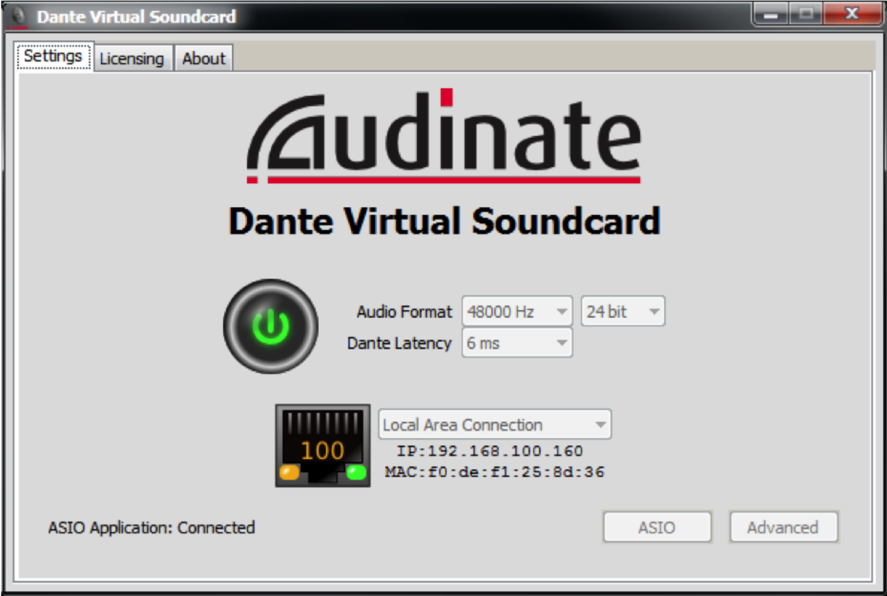
4) Launch the Dante Virtual Soundcard by clicking the Control Panel button.
5) Turn on the Dante Virtual Soundcard by clicking the Power button. It will turn green when active.
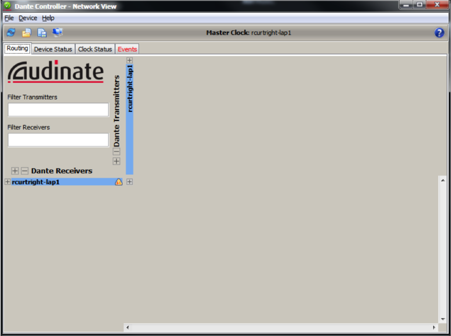
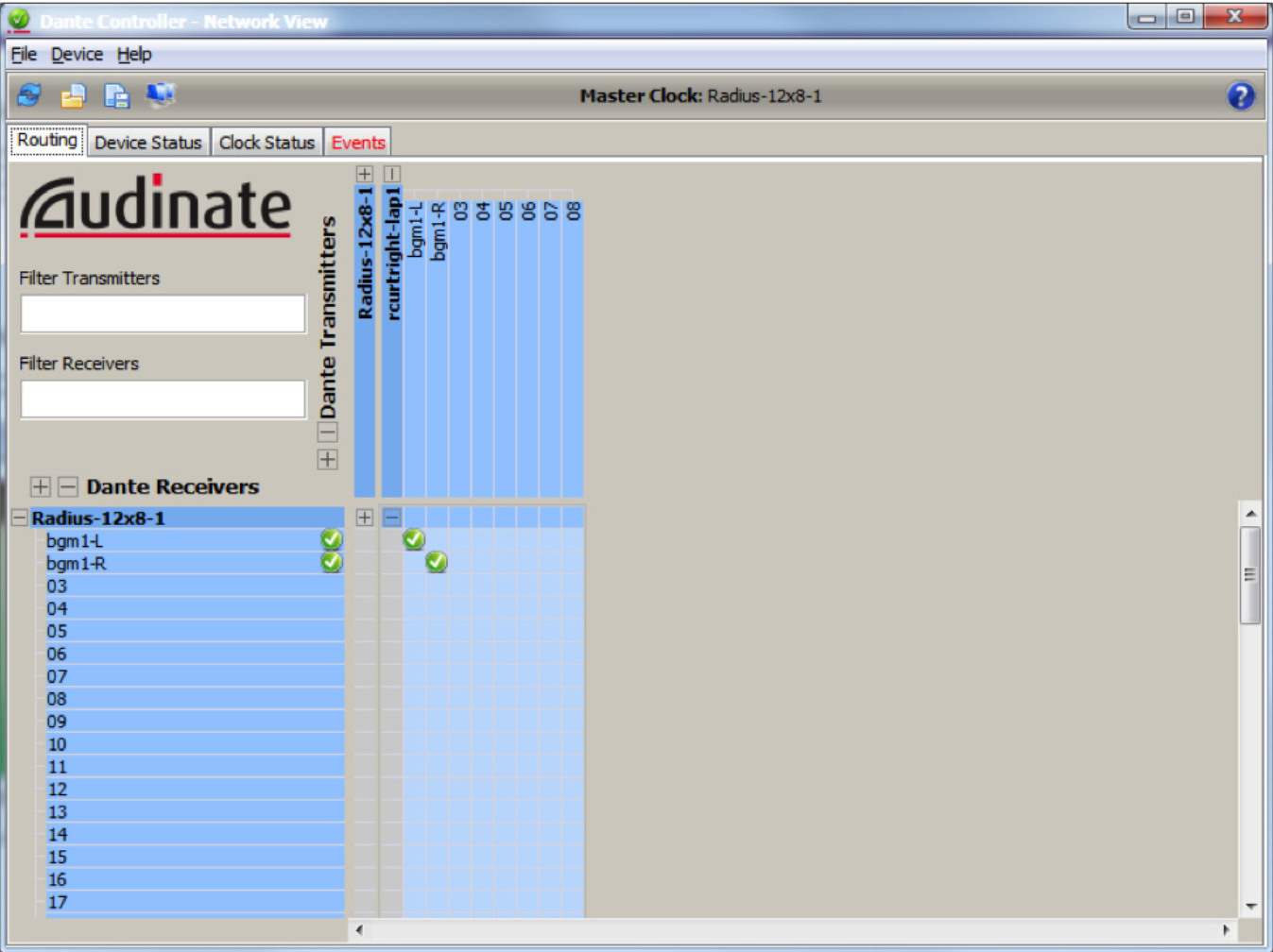
6) Open Dante Controller located at Start->All Programs->Audinate->Dante C controller.
7) The Dante Device Network Name of the PC or MAC running the Dante Virtual Soundcard (DVSC) should be visible on the Routing page. In this example the name of the Dante network device is rcurtright-lap1. Write this name down for a later step.
8) Next, click on the Device Status tab, and then double click on the device name. In this case it is rcurtright-lap1. This will launch the Dante Controller Device View.
9) Click on the Transmit tab and then label all channels which you would like to receive in the Edge or Radius.
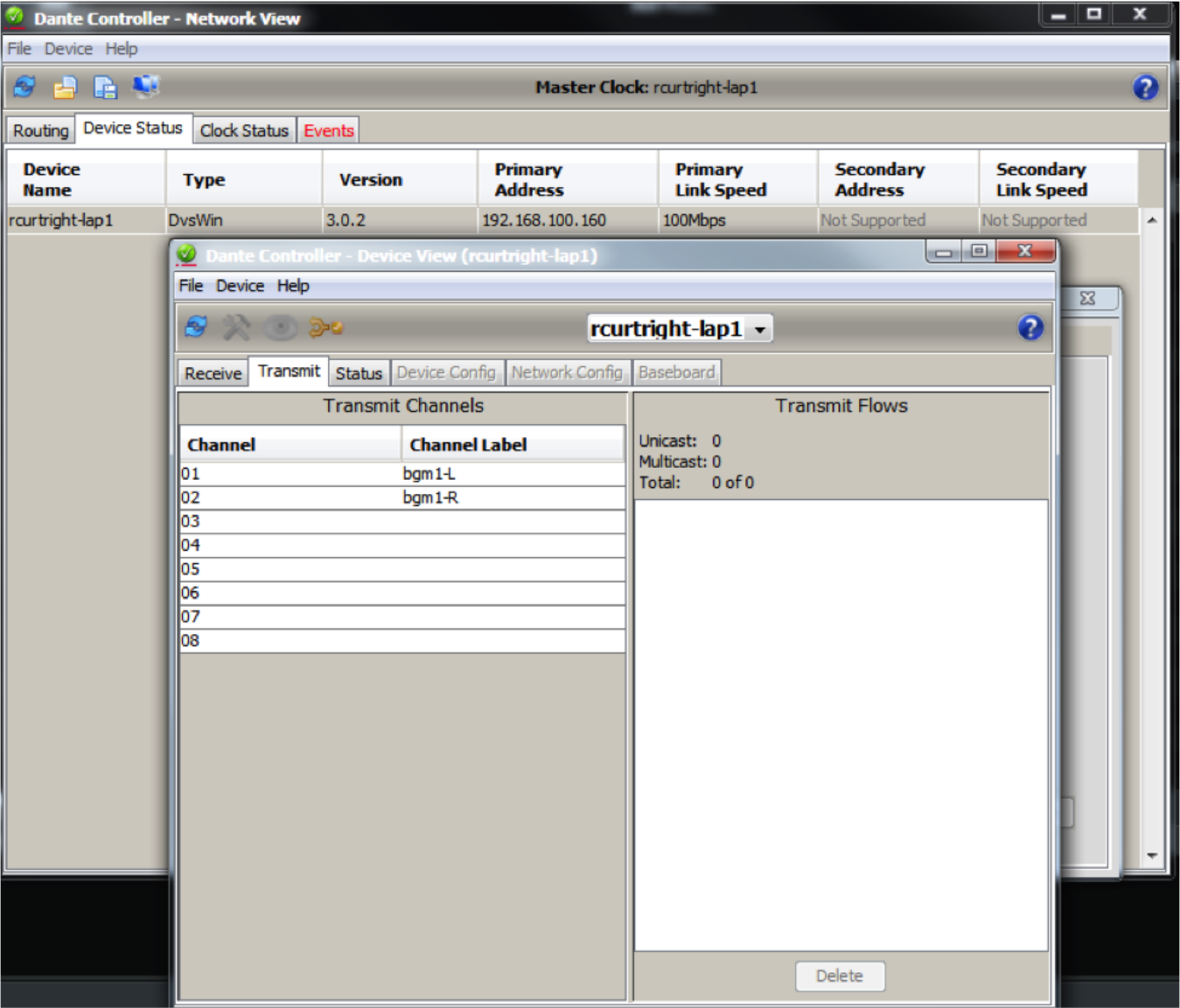
Since Winamp is being used, only 2 channels are needed to carry a stereo signal which has been named bgm1-L and bgm1-R in this example.
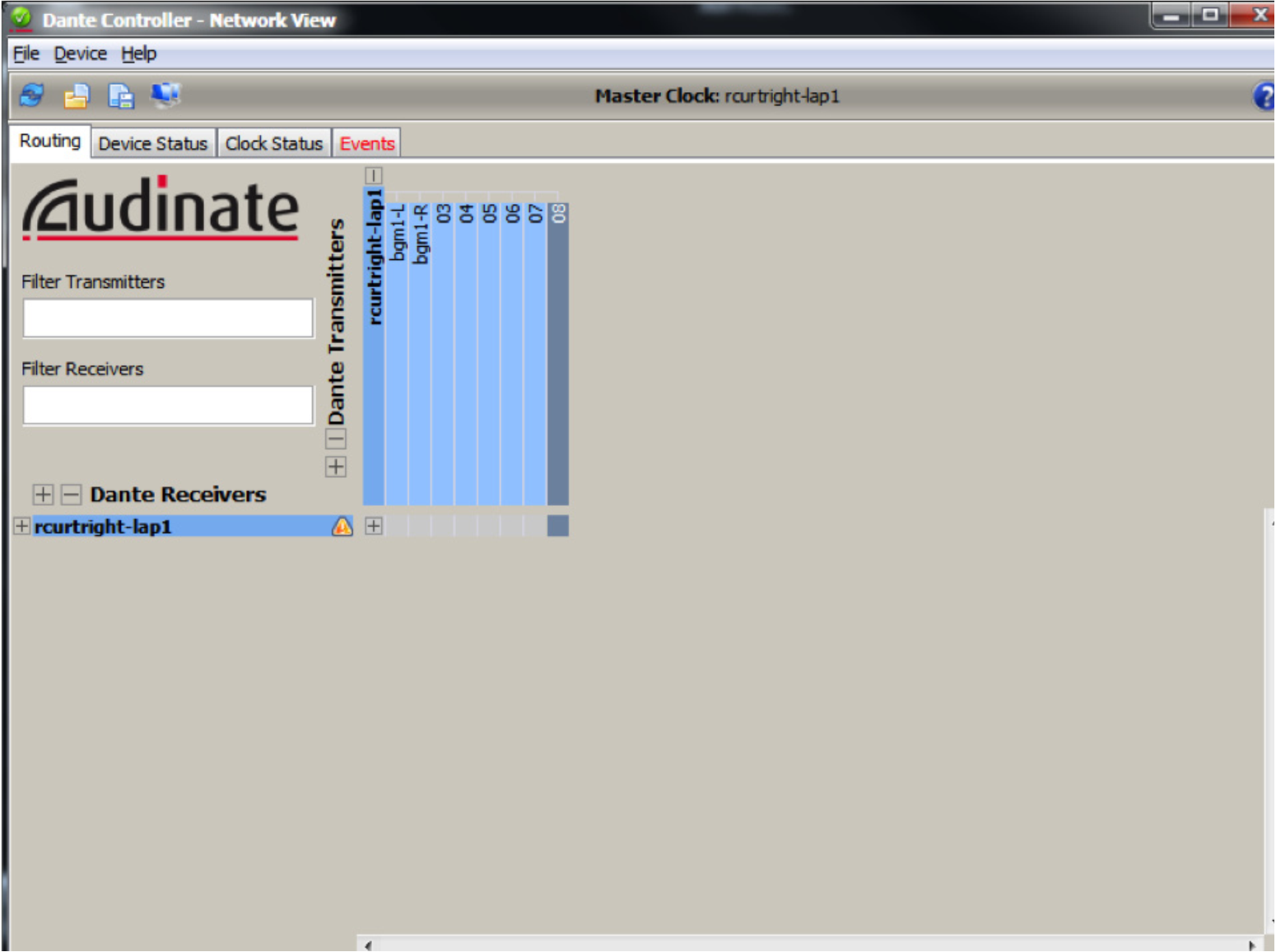
10) Now, on the Routing tab, expand the device in the upper area of Dante Transmitters and confirm that the two named channels are now listed.
11) Next, open Composer, locate hardware (Ctrl+Shift+L), and then enter the design view by double clicking on the Edge or Radius DSP icon.
12) In the Toolkit expand “Dante Transmit and Receive Flows” and drag a New Transmit/Receive Flow into the design.
13) A new Dante flow will be created and Dante Flow Module Properties will pop-up.
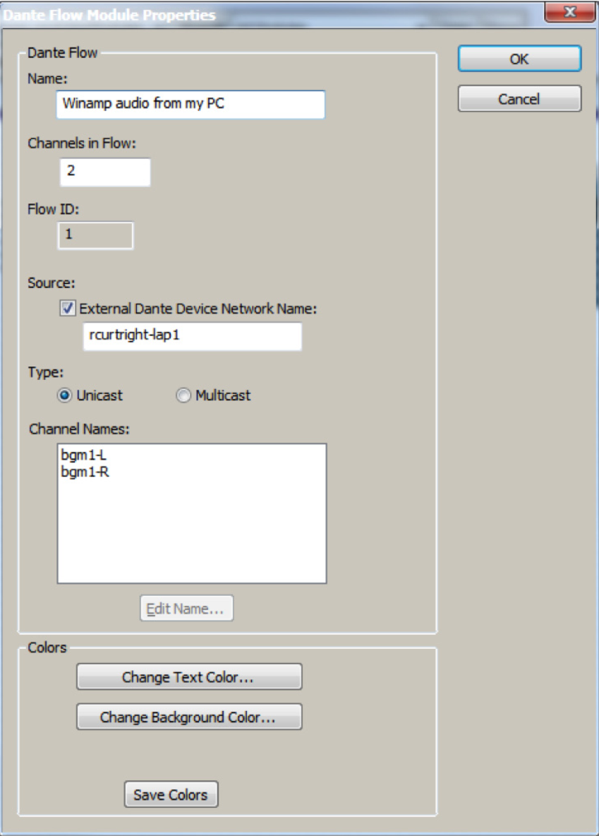
- Name for new Dante Flow: can be anything and is only for organization in C composer.
- Channels in Flow: can be 1-8 channels, although this examples uses 2 for stereo content from Winamp.
- Place Dante Flow Module: set to receive.
- Source: check the box for External Dante Device Network Name and enter the network device name from step 7. It must be typed exactly as displayed including any special characters or spaces in the name.
- Type: unicast.
- Channel names: name both channels with exactly the same names given in step 9 using Dante Controller.
14)Wire the Dante modules outputs into any module input or analog output. In this example Dante is wired into a stereo matrix mixer.
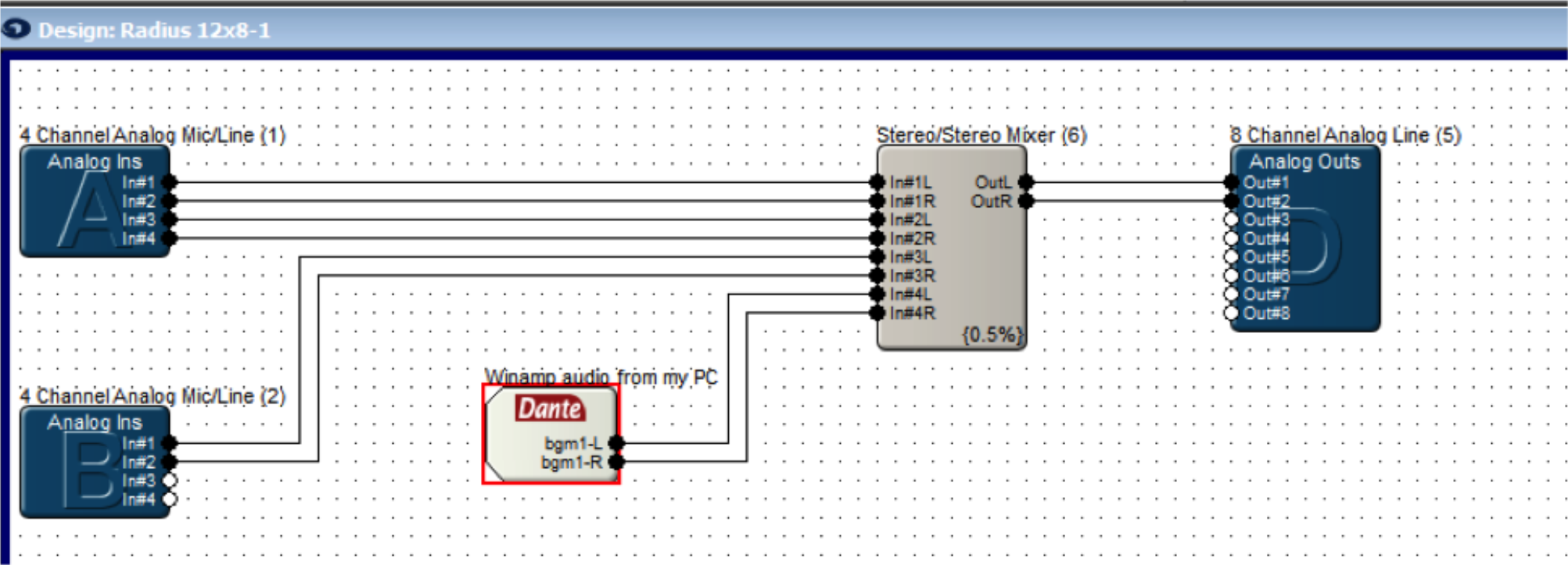
15) Push the site file to hardware.
16) In Dante Controller on the Routing Tab with Dante Receives and Dante Transmitters expanded the Edge, Prism, or Radius NX DSP should now show a connection between the DVSC channels.
17) In Composer opening the GUI for the Dante Flow should show audio on the meters, as long as a song is currently playing in Winamp.
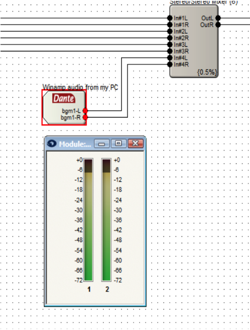
Note: setting Winamp to repeat a song or to playlist is suggested for continuous audio.
Note: Dante network audio is 24bit / 48khz audio. This means that playing a mp3 in Winamp which is 16bit / 44.1khz audio will cause it to be pitch shifted due to the 44.1khz audio being played at 48khz by the device. For true testing purposes use software that can play 24bit / 48khz audio, a common example being Sound Forge.
Once you’ve installed the Symetrix driver (Symetrix USB Audio v4.14.0 Setup) on your Windows machine and configured the USB Audio Card to run in 8×8 mode, switching to 1×1 modes may result in interrupted audio. After you’ve pushed a 1×1 configuration:
- Navigate to the Windows Control Panel.
- Select Sound.
- On the Playback tab, double-click the Symetrix USB Audio device “Echo Cancelling Speakerphone”
- Select the Advanced tab.
- Ensure that “1 channel 16 bit 48000 (DVD Quality)” is selected for the Default Format. If correct, it will be un-selectable as the above example shows. If the selection is missing the (DVD Quality) tag, click on the correct option in the dropdown menu.
- Select OK to close the USB Card Audio “Echo Cancelling Speakerphone Properties”.
- Repeat steps 3 thru 6 for the Recording tab.
- Select OK to close the Sound menu.
The Digit Map (also called the Dial Plan) defines a collection of digit pattern templates that are used to match valid dial strings, for example 7-digit or 10-digit dialing, as the user enters digits. Once a pattern has been matched, the call is placed using the digits that have been entered. These patterns are used to make it easy for an end-user to dial the requisite digits including internal extensions, emergency numbers and external numbers and have the system dial automatically once the proper number and type of digits have been entered.
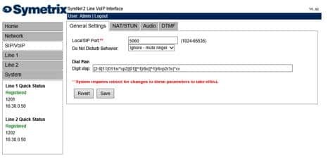
A quick reference can be accessed by placing the pointer of the mouse over the Digit Map field.
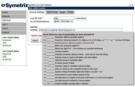
The following table provides a quick summary for all possible Digit Map parameter values.
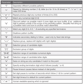
Each of the above parameters, when not used as an informational character, will represent a single digit. This includes if the parameter uses multiple characters for informational reasons.
Below is a detailed view of the default Digit Map:
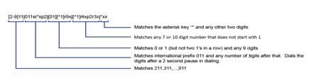
The following examples show how individual patterns are matched:
[3469]11
Allow 311,411, 611 and 911
Each of the items represented in the [] are seen as a single digit. This means “3 or 4 or 6 or 9” plus “11”
1900r7x!
Disallow a 1-900-XXX-XXXX number.
This will tell the system to look at the first four (4) digits of the entered number, and if they match “1900” drop to a failed tone.
976r4!
Disallow a 976-XXXX number from being dialed
This will tell the system to look at the first three digits of the entered number, and if they match “976” drop to a failed tone.
1800r7x
Allow a 1-800-XXX-XXXX number
This will tell the system to look at the first four digits of the entered number, and if they match “1800” dial using 1800 plus the remaining seven digits.
[^1]r6x
Allow a seven digit number not starting with 1, (2XX-XXXX – 9XX-XXXX)
This will tell the system to look at the first digit, if it is a “1” discount the input as a possible match. However if the string starts with any number between “2-9”, then dial using that digit plus the remaining 6 digits.
11[02] Allow 110 and 112
This tells the system to match the digits “11” and either “0” or “2”. For German emergency services, 110 is the Police and 112 is the Fire Brigade.
Some examples for various extensions:
“4xxq” – Matches 3 digit extension beginning with ”4”
“4xxxq” – Matches 4 digit extension beginning with ”4”
“4r4xq” – Matches 5 digit extension beginning with ”4”
“4xxp1xq” – Matches 3 and 4 digit extension beginning with ”4”
“4xxp1xp1xq” – Matches 3, 4, and 5 digit extension beginning with ”4”
The final “q” in the above strings tells the system that if an additional digit is pressed outside of the scope of the preceding pattern, disqualify that string as a possible match and look for another match elsewhere.
1010Se#e*p2r*x
This pattern tells the system to match a “0”, then after pushing a “*” or “#”, allow the user to enter in as many digits as the system can handle, then dial the entire string.
To set up a dial pattern that would allow the user to easily dial between two services, use the <:> symbol. By putting <[89]:> as part of the dial pattern, the system will replace an ”8” or ”9” with a null value, and continue pattern matching as necessary. For example: “<[89]:>r7x”, as long as the first digit is an ”8” or nine ”9”, this pattern will take the set of numbers, remove the first number, and dial out using the remaining seven digits. The user can then put an ”8” as part of the pattern recognition string for one provider, and ”9” as part of the pattern recognition for another provider. This will allow users to easily dial between providers with similar numbers. If one enters two different patterns which could be easily confused, the system will choose the first pattern that is matched. For example, if two patterns, one for eleven digits followed by one for twelve digits, the system will not wait for the twelfth digit, as it will match to the eleven digit pattern first.
Having a general understanding of the AEC module parameters prior to reading this Tech Tip is essential for success during the programming and commissioning stages of the conferencing system. All parameter definitions are covered in the Composer Help file. This Tech Tip outlines some tips and tricks to get great results fast from the Radius NX and 4 Channel AEC Input Card. Keep in mind, room acoustics, mic and speaker placement, and gain structure are the cornerstones of getting the best results in any AEC installation.
Essential Concepts for Successful AEC
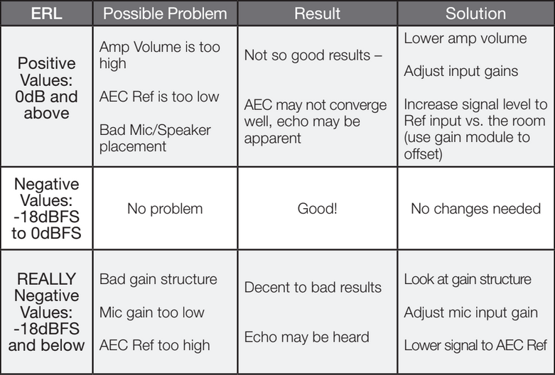
ERL: Echo Return Loss is the difference in signal level between the audio which is present at the reference input and the same audio measured in the room by the microphones. For best results the ERL should be maintained between +/- 10 dB. A 0 dB reading would indicate that the algorithm is working with optimum efficiency.
Reference: The reference should be tapped off the signal path as close as possible to the local reinforcement outputs so that any processing latency, filtering, or delay that are applied to the analog outputs are also applied to the reference input.
Reference Offset: In order for the ERL to be maintained at +/- 10 dB, it is sometimes necessary to offset the level of the audio sent to the reference input at 7-10 dB louder than the same audio entering the microphones. When the room gain is turned up, the level of the far end audio at the microphones is turned up as well. Using a two channel gain module’s master fader for room gain will turn up the reference and the room gain together, maintaining the necessary offset between the reference and the same audio at the microphone input. See Example 1. If the ERL is reading more than +/-10 dB, turn down the speakers in the room or turn the reference signal slightly up using the reference offset gain module.
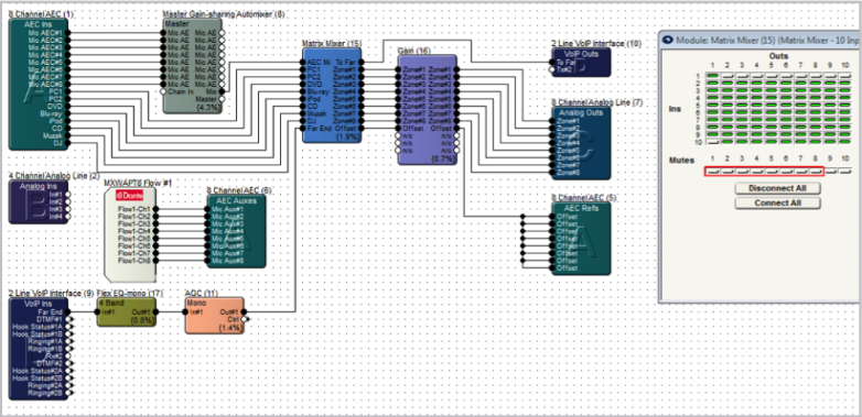
Example 1: AEC Basic
Notice in this example the reference is tapped off after all dynamics and filtering has been applied to the far end audio. This means the audio at the AEC reference is as acoustically close as possible to the far end audio as it enters the AEC microphones.
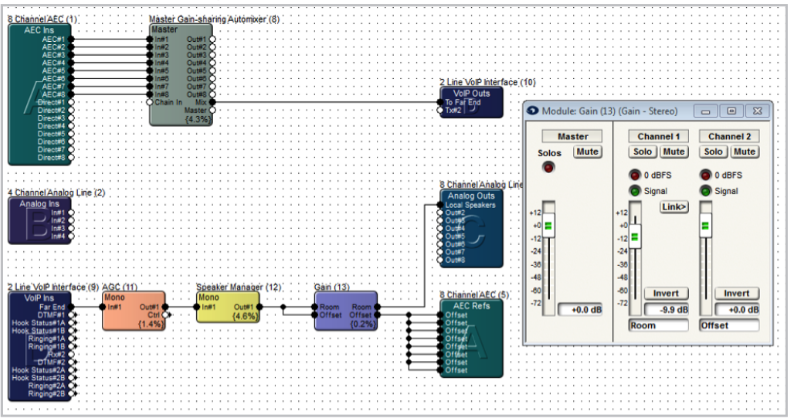
In a best case scenario the room volume would be set to a static operating level tuned for best AEC results. However, if the customer requires level control, you can include a gain module prior to the reference input and room outputs. Remember, the reference should be 7-10 dB louder than the same audio being picked up by the mics from the speakers. In the example above, gain module (13) gives the end user the ability to adjust the room level with the master fader. The individual input 1 and 2 faders create and maintain the 7-10 dB offset between the reference and the room volume. As the end user turns up the room volume, the reference signal also goes up with it.
Example 2: AEC with Local Mic Reinforcement + Mix Minus
The AEC algorithm adds 11 ms of latency which would be distracting if used for the local sound reinforcement. For local reinforcement use the direct outputs of the 4 channel AEC input card instead of the AEC outputs. Each set of outputs should be feeding their own Gain-Sharing Automixer before passing through a matrix mixer, which provides the mix minus capabilities and routing to the local sound and far end.
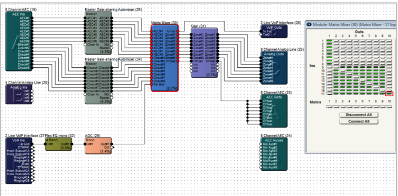
Again, the AEC reference point and local speaker outputs need to be tapped after all processing, and right before the outputs.
Example 3: AEC Dante Flow to Aux inputs (using Shure Dante MXWAPT8 mics)
The Radius AEC and/or SymNet 4 Channel AEC Input card can apply the AEC algorithm to either the analog inputs or any source routed to the AEC Auxes.
In this example, the AEC is applied to Shure Dante MXWAPT8 mics whose audio enters the SymNet DSP through the Dante bus, while the physical inputs on the AEC Ins module are utilized for additional non-AEC sources via the direct inputs, such as PC audio.
Gain Structure
Follow these steps to set up an AEC Conferencing system with proper gain structure.
- Start with the power amps turned down all the way.
- In the AEC module, adjust the mics input gains so that the meters are showing about -20 dBFS during normal talking level into the mics. Start with the level, and then use the fine trim control.
- Adjust the rest of the gain structure through the entire system for unity gain (-20 dBFS).
- Then establish a connection to the far end, and then slowly bring up the level on the amplifiers, until the appropriate loudness is obtained.
- Adjust the near end mics levels and far end transmit receive levels as required.
- Check the ERL (Echo Return Loss) values. ERL is a measure of how loudly the far end signal is coming out of the near end speaker, and entering the near end mics. This is a visual indication of how hard the AEC process must work to remove echo. ERL will normally be negative; if it is positive or too negative, it may indicate a gain structure problem.
- Once operational, make minor level changes as required, but do not change the level of the amplifiers.
- Engage NLP (Nonlinear Processing) if in a particularly troublesome environment and you still hear echo. Nonlinear processing is useful for removing the secondary indirect echo, often heard as reverb NLP can be very useful and transparent to the participants; however, use of heavy NLP in troublesome environments can reduce double-talk performance and clarity.
- Engage Noise Cancellation if needed to control steady state background noises such as computer fans and HVAC systems.
- Engage AGC (Automatic Gain Control) to compensate for varying distances between the near end participants and their mics. It attempts to maintain a consistent level for better intelligibility.
Troubleshooting Residual Echo:
- Amplifier is turned up too high.
- Mics may be too close to the speakers, or pointed directly towards the speakers
- Input gain on the mics could be set too high.
- Not a high enough signal is being fed to the AEC reference.
- Gain structure is not optimized.
Routing
Here’s a quick reference routing checklist for the site file listing where items should be routed.
- Direct mic inputs are routed to local speakers only.
- AEC mic inputs are routed to the far end only (ATI, VoIP, Codec, etc.).
- Far end inputs are routed to local speakers and refs.
- Audio sources, PC, BGM inputs are routed everywhere (local speakers, far end, and refs).
Troubleshooting
These troubleshooting techniques can be used when implementing an AEC design.
Top reasons for bad AEC result:
- Bad gain structure
- Incorrect mic and speaker placement
- Bad room acoustics
- Local reinforcement is too loud
- ERL showing more than +/-10 dB
- The reference signal tapped off prior to dynamics, filtering, or delay processing
Troubleshooting Residual Echo:
- Verify that the routing to the AEC reference is correct.
- Meter the signal feeding the AEC reference and make sure it is within the recommended range (average -20 dBFS).
- Adjust NLP settings from off to low. If echo is still being heard, switch to high.
- If customer is using an analog phone line. Try removing the Radius AEC from the equation. The use of a “Butt Set” or standard analog phone can help to quickly determine if the echo is being caused with the AEC or on the actual phone system itself. If an analog line is an extension of an IP phone system, the system itself can have an echo. Simply unplug the phone line from the Radius and connect it to the “Butt Set” or standard analog phone. Make a call into the system and out from the system. If you still have an echo, the problem is not within the AEC. If the echo goes away, the problem is within AEC.
Symetrix provides cutting edge acoustic echo cancellation (AEC) for audio conferencing and video conferencing applications. With only 11ms of latency, the Symetrix AEC algorithm is one of the fastest acoustic echo cancelling algorithms in the conferencing market. Couple the speed of the AEC algorithm
with the pristine, high fidelity, audio Symetrix provides, including Dante digital bussing capabilities, there is little wonder why for many A/V Integrators Symetrix is becoming the preferred DSP system for small to larger conferencing systems.
Symetrix provides AEC and audio conferencing options native to the system; however, when video conferencing is needed, a 3rd party video codec system will be integrated with a Symetrix system. As such, it is important that the correct inputs and settings are used on the Lifesize system to provide the best audio possible during the video conference.
Lifesize 220 Input to Use with Symetrix Output:
All Lifesize 220 models have several inputs; however, when a Lifesize codec is integrated with Symetrix, the Symetrix system will provide the AEC. As such, it is important to use the (No AEC) inputs on the Lifesize codec for receiving the microphone and media sources from device. Using an input on the Lifesize codec with AEC can cause artifacts associated with processing the already “echo free” audio with AEC a second time.
Below is a chart with the Lifesize models and “No AEC” input options. The
mix that has the audio for the far end caller should be connected to one of these No AEC inputs.
From the Lifesize User Guide:
Lifesize 220 Output to Use with Symetrix Input:
The Lifesize codec is providing the audio from the far end to the Symetrix system. This far end audio is used as the reference (REF) as well as being sent to the local speakers. The “Line Out” of the Lifesize codec should be connected to an analog input on the device. When using a Radius AEC, one of the four line inputs should be used. If a Lifesize phone is used in conjunction with the system, the Voice Call Audio Output should be routed to the Lifesize Line Out as well.
Below are pictures of the Lifesize 220 models. The correct Lifesize input to connect to the output which will carry the local audio to the far end is highlighted in red on each model. The correct Lifesize output, also known as the reference or “REF”, to connect to the input is highlighted in blue.
Lifesize Express 220:
Lifesize Team 220:
Lifesize Room 220:
The purpose of this Tech Tip is to explain how to integrate the Earthworks IML & IMBL Microphone and LumiComm Touch Ring with a Symetrix DSP. The Earthworks LumiComm Touch Ring features a dual-color LED light ring and a touch sensor output. The light diffuser houses 10 LEDs providing side illumination (5 Green, 5 Red). The logic controlled LumiComm Touch Ring provides system integrators complete freedom
to assign functions and LED color.
The Earthworks IML & IMBL Microphones and the LumiComm Touch Ring can be supplied with either a 5 pin Phoenix connector or an 8 pin R-J45 connector.
The LumiComm Touch Rings current consumption is 85 mA with 5 LEDs lit and 170 mA with 10 LEDs lit, so an external power supply is needed. A “regulated” power supply from 8-28 VDC can be used. Always check your power supply polarity before connecting your supply to the LumiComm Touch Ring.
The wiring diagram below uses the Earthworks IMBL Phoenix connector in this
example. Each connection between the Phoenix connector and the Symetrix DSP is
explained below.
Pin 1) Ground – This connects to both the ground (-) connection of the external power supply, as well as the ground connection of the External Control Input or the Logic Output used on the Symetrix DSP.
Pin 2) 8-28 VDC power supply – This connects to the (+) connection of the external power supply.
Pin 3) Touch Sensor Output – This connects to the External Control Input used on the Symetrix DSP. In this example, CTRL input 1A is used.
Pin 4) Red LED – This connects to the Logic Output on the Symetrix DSP used to activate the red LED. In this example Logic Output 2 is used.
Pin 5) Green LED – This connects to the Logic Output on the Symetrix DSP used to activate the green LED. In this example Logic Output 1 is used.
Symetrix DSP’s are equipped with 3.3V pull up digital inputs, so a 10K resistor is not necessary as shown in Earthworks documentation.
To create the programming for the LEDs we recommend using our Button Processor Super-module, which is included in Composer software. 1-button, 4-button and 8-button versions are included in Composers Super-module library.
The Button Processor Super-module makes it extremely easy to integrate these microphone’s push-to-talk switches into your DSP. Four different modes are available per mic switch; Push to talk, Push to Mute, Toggle, and Disabled.
- Start by importing a 1-Button Processor Super-module into the design:
- Drag in a 1-Button Momentary module from the toolkit, and wire to the “Button 1” input on the super-module.
- Double-click the 1-Button Momentary module to bring up its GUI. Right-click directly on the “On” button, then click “Set Up to Remote Control” and select the Local Analog Input from the “Remote Control Device” dropdown menu. Then select which switch is being used under the “Select Analog Control” dropdown menu. Switch 1A is used in this example.
- From Control Modules->Control Outputs, drag in the “Local Logic Output #1” module. Wire the On/G output from the Button Processor Super Module into the Local Logic Output 1 module.
- From Control Modules->Control Outputs, drag in the “Local Logic Output #2” module. Wire the Off/R output from the Button Processor Super Module into the Local Logic Output 2 module.
- Navigate to the Mute button for the mic channel you’re planning to control. Right-click it, select “Set Up to Remote Control” and choose “Control Signal Assignment”. Click the “Select” button, and click the plus sign next to “1-Button Processor”. Highlight “1 Off/R”, then click OK.
- Open the Super-module user interface and select the preferred switch mode. In this example the Toggle mode is used. Go online and test the switch while watching the super-module GUI. The Input LED will light when the switch is closed, and the On/Mute LEDs will respond accordingly.
This Tech Tip will explain how to integrate the Clockaudio CH32 illuminated Halo LED touchpad and a cardioid desktop microphone with a Symetrix DSP. It should be noted that any future Clockaudio products utilizing a bi-colored status indicator and switch will be standardized, using the same color code and connection method. At present, this tech tip is valid for the CH32, TS001, SM80S, S80, and CSS Series (CS1S-CS4S).
The integration of Clockaudio conference systems can be performed with any Symetrix DSP that has analog control inputs, however this tech tip uses an Edge specifically in all examples. The CH32 is a translucent white, bi-color Halo Ring which includes a touch pad switch. There are (16) Red and (16) Green LEDs in the ring. The logic outputs on the Edge unit can power single LEDs, but cannot provide
the 60mA @ 12 VDC required to power the entire Halo Ring.
It is necessary to employ an external 12 VDC regulated power supply, in order to operate the CH32.
| Cable Color | Function | RJ45 Pin Number |
| Red | Red LED | 2 |
| Blue | -V Switch | 3 |
| Brown | +V (12 VDC) Switch | 4 |
| Yellow | Switch Logic Control | 5 |
| Green | Green LED | 6 |
The CH32 has a wire pigtail with an RJ45 connector crimped on one end. The product comes with an RJ45 straight-through coupler to facilitate the connection to a permanently installed CAT5/5e/6 cable.
Please be aware that the wiring scheme may vary on your specific model of CH32. Always double check the manufacturer’s documentation for the exact wire coloring of your model CH32.
There are (3) important connections which need to be made between the CH32 and Edge.
1) The Ground, Red LEDs, and Green LEDs wires from the CH32 should be connected to the Edge’s Logic Outputs. For this example, use Logic Output #1 for the Red LEDs and Logic Output #2 for the Green LEDs.
2) The Ground and Switch Control Logic wires should be connected to Edge’s External Control Inputs. For this example, use External Control Input #1 for the Switch Control Logic.
3) Plus, minus, and ground of the audio line from the microphone should be connected to an Analog Mic/Line Input channel on Edge.
The final important connection is to an external power supply. In this example, a 12 VDC external power supply is connected across +V and –V/Ground. When the Green LEDs or the Red LEDs wire is grounded by Edge’s Logic Outputs, the associated set of LEDs light. The Switch Logic Control wire will be open, or closed with respect to ground. The circuit’s state is determined by toggle logic and should be connected to the Edge External Control Input.
It is the integrator’s responsibility to configure (2) functions within the Edge unit:
1) Touching the CH32 triggers a logic function on the Switch Logic Control wire. This contact closure must be connected to an External Control Input on the Edge unit and assigned to a parameter in software such as a Latched Button, then wired into a control process such as a Flip-Flop, in order to trigger a set of presets that mute and un-mute the microphone associated with the CH32.
2) The presets triggered by the contact closure after touching the CH32 should also include a parameter that pulls either the Green LEDs wire or the Red LEDs wire to ground on Edge’s Logic Outputs connectors.
The integrator must decide whether it is desirable for the customer to have Red LEDs lit when the conference microphone is muted, or when it is open and in use.
Then, the presets in the Edge should be configured so the proper wire is pulled to ground according to the lighting scheme the customer wishes to have.
Please refer to the diagram below as an example of wiring a CH32v02 to Edge’s Logic Outputs, External Control Inputs, and Analog Mic/Line Inputs:
NOTE: The coupler that ships with the CH32 has its corresponding pins visually in a crossover pattern if looking down directly at the coupler. The coupler’s pin pattern is directly duplicated on the opposite face. The wiring diagram above displays the colors considering that only pins 2 – 6 are used and assuming that the same colors are continued on the other side of the coupler.
A Symetrix system’s I/O can be comprised of a combination of hardware, from DSPs such as D100, Edge, Radius NX, or Prism to the I/O expanders such as the xIn12, xOut12, and xControl. Pushing the site file programming from the host PC running Composer Software to the system can take anywhere from a few seconds to a few minutes depending on the amount of hardware that must receive programming.
Often times during commissioning, pushing the file to the system will be performed many times over as changes are made to the signal flow, remote controllers, presets, or parameters, and of which it is desirable to listen to these changes and/or to save these changes permanently in the system. By speeding up the Push process, it is possible to shave many minutes off of the overall commissioning time of the system.
The first thing to note is that all control and routing is truly performed in the DSP units. No processing or control is actually performed in the xIn 12, xOut 12, or the xControl, as once programmed these devices simply send audio or control to the d100, Edge, Radius NX, or Prism.
What this means is that once the xIO have had their programming pushed into them, then changes to the site file signal path, DSP modules, or control will not typically include changes to the xIO devices. As such, disabling them from the Push process will eliminate needlessly reloading the same programming into these devices whose settings/programming is not changing between each subsequent push.
Take this example site file. It includes Edge, Radius NX, xIn 12, xOut 12, and xControl hardware. Before disabling the xIO units from push, first locate all hardware and push the design (F4) to program all hardware, including the xIO devices.
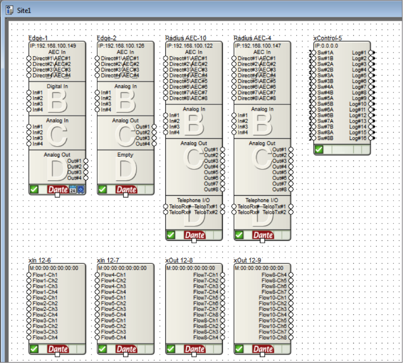
Then right click the xIO hardware and choose “Unit Properties”. When the Unit Properties window pops up, uncheck the enable box (highlighted in red below). Doing this will disable the unit from each subsequent push of the site file. Disabling a unit does not affect the unit’s functionality. To repeat, the
disabled units will continue to operate normally and communicate to the DSP hardware, they will simply be ignored by Composer software during the push process.
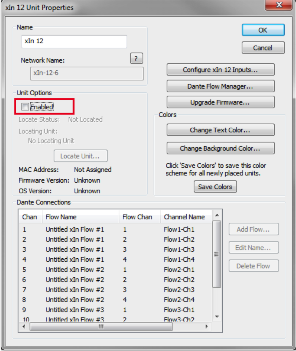
Once all xIO units are disabled, the push process will now update only the programming on the Edge, Radius NX, Prism, and D100. And as this document explains, over the course of the commissioning process, eliminating unnecessary units from being reprogrammed over and over will shave many minutes off the commissioning process.
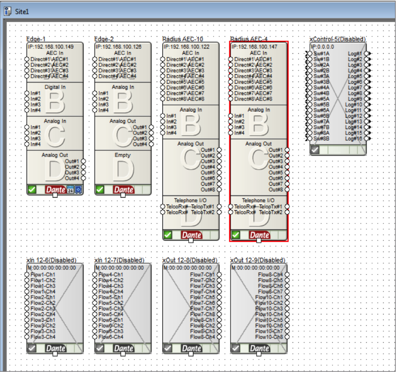
It should also be noted that at any time these disabled xIO units can have their configuration edited by simply checking “enable” in the Unit Properties, making the necessary changes, and pushing the file.
Symetrix DSP units are equipped with analog control inputs. These inputs can be utilized in various ways to provide control or trigger events.
Common uses include:
1. Emergency muting via fire alarm relay.
2. Volume control via 10k pot.
3. Source select or preset recall via multi-position switch.
Option number 3 can present a problem called “contact bounce”.
Contact bounce (also called chatter) is a common problem with mechanical switches and relays. Switch and relay contacts are usually made of springy metals that are forced into contact by an actuator. When the contacts strike together, their momentum and elasticity act together to cause bounce. The result is a rapidly pulsed electric current instead of a clean transition from zero to full current. The effect is usually not important in power circuits, but causes problems in some analog and logic circuits that respond fast enough to misinterpret the on-off pulses as a data stream.
On a SymNet DSP the scenario might be as follows: A multi-position switch is connected to an analog control input across V+ and IN with a resistor inline with the IN. This allows the switch to have 3 states rather than just 2. In software this analog control signal is assigned to a control fader that outputs to three range detectors that are set to the three levels that the switch outputs. The output of the range detector could be assigned to a control directly or used to trigger presets. The following configuration would be the logical solution.
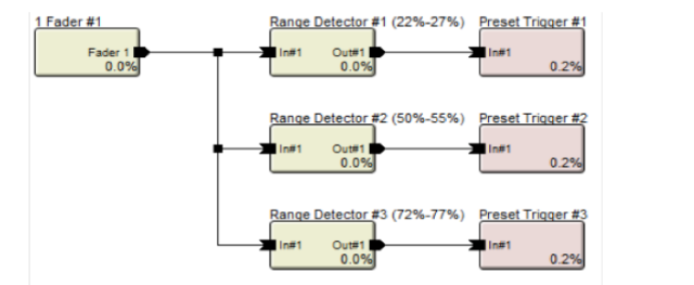
The problem occurs when making a selection on the multi-position switch, for a brief moment the voltage may bounce to 0% or 100%, causing the other presets in between the desired setting and the bounce to trigger unexpectedly.
NOTE: Whether the bounce will go to 0% or 100% may vary from one model of switch to another.To fix this problem we need to add a time delay so that the contact bounce has settled before the contact input is used. Here is the configuration with the added time delay and logic.
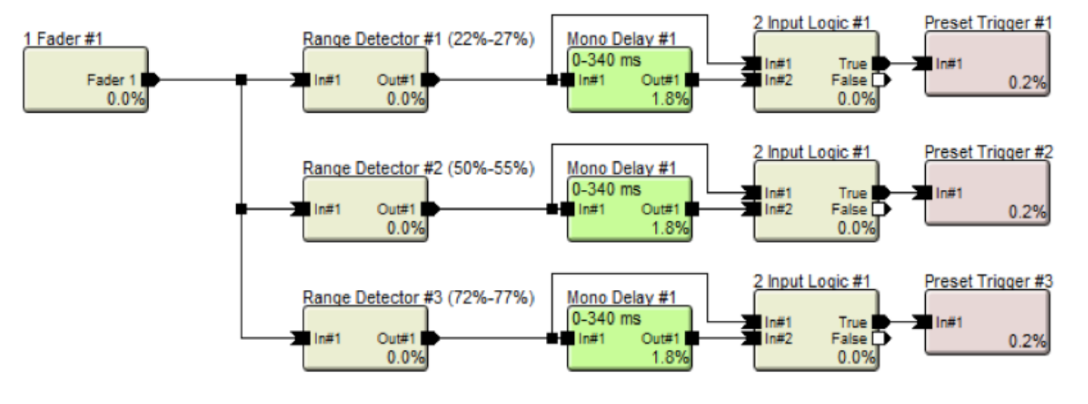
The delay time sets how long the control signal must be settled and consistent before triggering the preset. A default setting of 100 ms is suggested. As long as the switch bounce settles before 100 ms, the bounce will not register and trigger unintended presets.
NOTE: The 2 input logic module must be set to “AND”. This is a solution where control and audio modules are mixed on purpose. Ignore any warnings from the analyzer which may indicate this configuration
The Symetrix 2 Channel Analog Telephone Interface card (ATI card) provides a simple and intuitive solution for audio conferencing applications. Acting as a built-in telephone hybrid, the ATI card provides the means for a Edge or Radius AEC to interface directly with an analog telephone line from the local
telephone company or an analog port from a digital PBX. The graphic user interface for the ATI card within Composer hosts all user controls for dialing a phone number, speed dialing a number, as well as picking up or disconnecting a phone call. The telephony controls are usually accessed by the end user via a SymVue control system or a 3rd party control system.
Crestron and AMX dialer modules have been created and can be downloaded from the Symetrix website. The downloadable folder for each includes the 3rd party dialer module as well as an example Site File:
https://www.symetrix.co/products/audio-io-and-control-expansion/#2-lineanalog-telephone-interface-card
There are two different methods in which a phone number can be dialed using the 2 Channel ATI card
Dialing a Phone Number One Digit at a Time:
When programming a 3rd party control system to dial the ATI card, each digit of the telephone number can be triggered one digit at a time by assigning a controller number to each of the ATI dialer buttons and then triggering them using the CS command outlined in the 3rd party protocol available here: https://www.symetrix.co/?wpdmdl=8
Controller Set Command = CS <Controller Number> <Controller Position> <CR>
The advantage to this method is that no special module need be created to dial the phone number. Instead, each digit on the dialer is treated the same as controlling any button or Boolean control in SymNet with a 3rd party control system.
This means the same control code that turns on or off a mute button can also be used to dial a number button on the ATI card dialer GUI.
Below is a picture of the ATI card GUI, in Composer, showing the telephone dialer. This picture was taken from the example Site file included with the Crestron and AMX ATI dialer modules. Controller #121 through #133 has been assigned to 1-9,0, *, #, and the connect/disconnect button, respectively.
Best Practice:
In Composer, number the controller numbers on the Dialpad sequentially to make it easier to control
and debug the control strings. Controller numbers can be added by right clicking on the control in Composer and selecting
Edit Remote Control Assignment.
As an example, in order to dial the Symetrix phone number, 1-425-778-7728, the third party control system would send the following commands:
Analog Telephone Interface Dialer
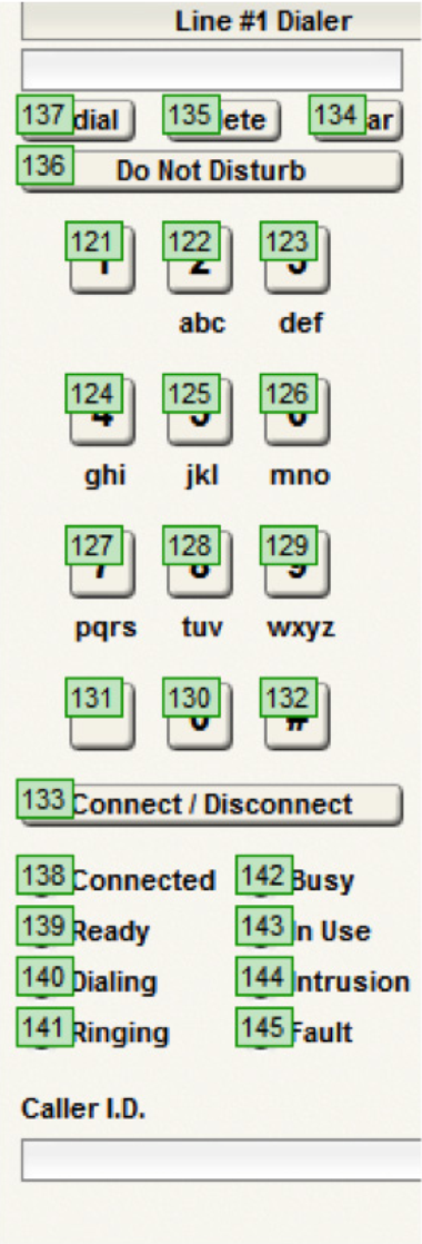
CS 121 65535\r
CS 124 65535\r
CS 122 65535\r
CS 125 65535\r
CS 127 65535\r
CS 127 65535\r
CS 128 65535\r
CS 127 65535\r
CS 127 65535\r
CS 122 65535\r
CS 128 65535\r
After each digit is entered, the Symetrix device will respond with an “ACK” if the command was interpreted correctly or a “NAK” if the controller number does not exist.
After the phone number digits have been entered, the call can be triggered to dial by sending the connect/disconnect button the following command:
CS 133 65535\r
The phone call may be hung up (placed on-hook) by sending the same command again:
CS 133 65535\r
Note: the function of the connect/disconnect button changes depending on if you are connected or
not. Always send 65535 for this value and it will toggle the connect states.
Dial a Phone Number Using a Speed Dial:
Some 3rd party programmers may prefer to create a custom dialing module that sends the entire phone number to the ATI card using a single command string, at which point the phone number can be dialed using a second command that dials the speed dial. The basis of using this two command method is that an ATI card speed dial slot is used as a phone number loading dock, and once the phone number has been loaded into the speed dial location, it can be dialed with a single command.
The ATI card has 20 speed dial locations, so if this method is used one speed dial location must be dedicated to the control system and the end user will 19 remaining speed dial entries.
The command to load the telephone number is the (SSYSS) Set System String command. It is important to note that this command assigns a system string, such as a name or phone number, to one of the speed dial locations and when applicable executing this command will over-write any previous data in the specified speed dial location. Set System String Command =SSYSS <Unit>.<Resource>.<Enum>.<Card>.<Channel>=<Value>
<Unit>=In the site view of the Composer site file, above each unit icon is a number after the dash, e.g. “Edge-1” means =1. (See picture)
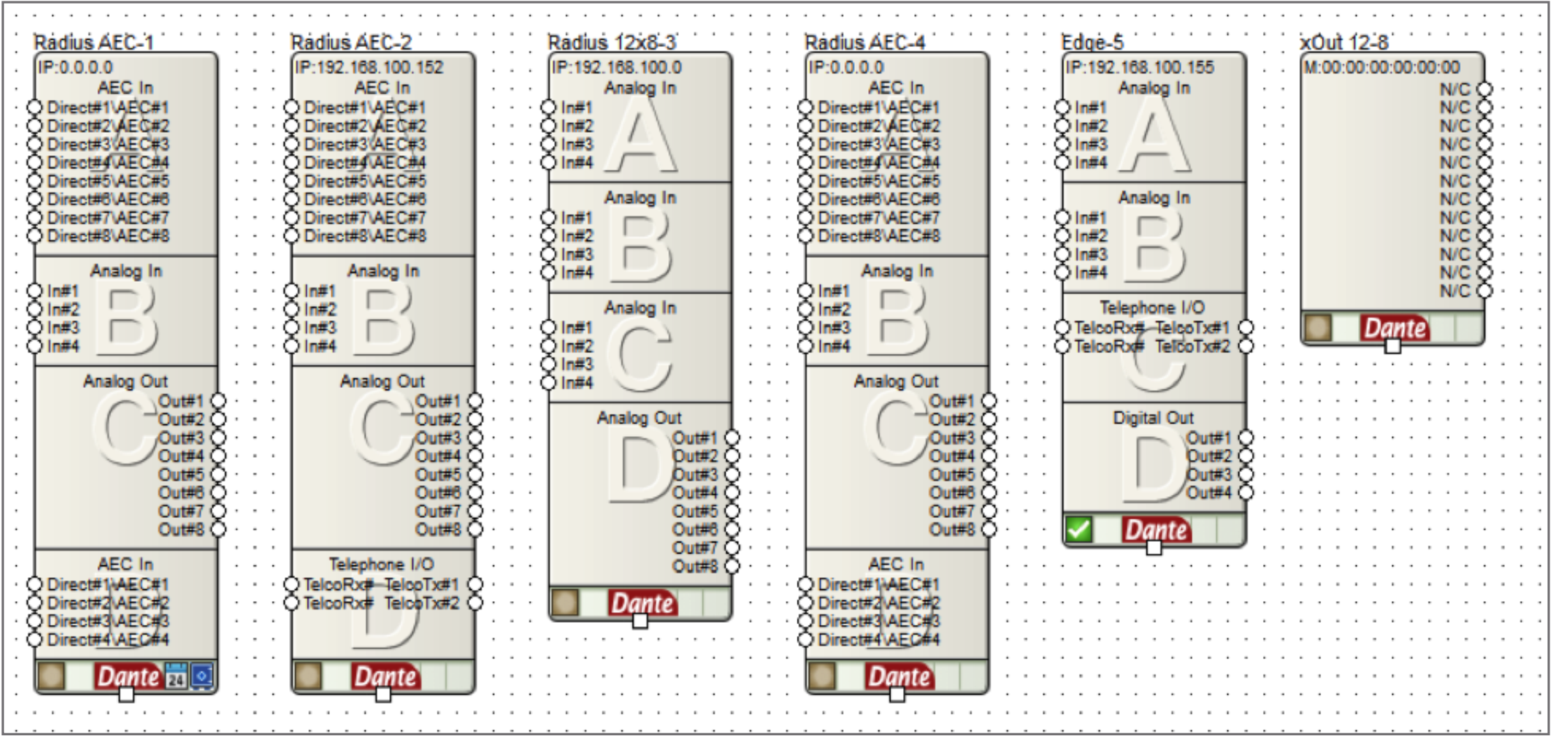
<Resource>= 1000 for speed dial number, 1001 for speed dial name.
Some 3rd party programmers may prefer to create a custom dialing module that sends the entire phone number to the ATI card using a single command string, at which point the phone number can be dialed using a second command that dials the speed dial. The basis of using this two command method is that an ATI card speed dial slot is used as a phone number loading dock, and once the phone number has been loaded into the speed dial location, it can be dialed with a single command.
The ATI card has 20 speed dial locations, so if this method is used one speed dial location must be dedicated to the control system and the end user will 19 remaining speed dial entries.
The command to load the telephone number is the (SSYSS) Set System String command. It is important to note that this command assigns a system string, such as a name or phone number, to one of the speed dial locations and when applicable executing this command will over-write any previous data in the specified speed dial location. Set System String Command =SSYSS <Unit>.<Resource>.<Enum>.<Card>.<Channel>=<Value>
<Unit>=In the site view of the Composer site file, above each unit icon is a number after the dash, e.g. “Edge-1” means =1. (See picture)
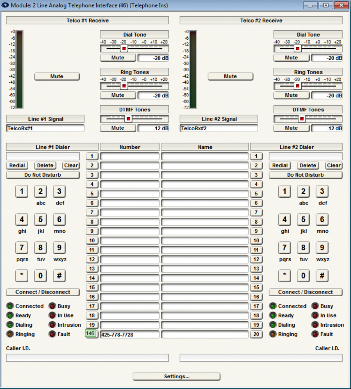
<Resource>= 1000 for speed dial number, 1001 for speed dial name.
<Enum>= 0 based count of 0-19, where 0-19 equals speed dial slots 1-20.
<Card>= 0 based count of 0-3 for card slots A-D. (A-D in Edge frame, D only in Radius AEC).
<Channel>=Not applicable for the SSYSS command since both ATI ch 1 and 2 share all 20 speed dial locations. Use a zero for this portion of the command.
<Value>= the phone number that should be assigned to the speed dial slot defined by <Enum><Card>
Example of SSYSS:
Notice the ATI card, “Telephone I/O”, in both the Radius AEC-2 and the Edge-5. If the intention is to store the Symetrix phone number into speed dial slot 20 on the Edge-5 unit’s ATI card in card slot C, the command would be determined as follows:
<Unit>=5
<Resource>= 1000
<Enum>= 19
<Card>= 2
<Channel>=0
<Value>= 425-778-7728
SSYSS 5.1000.19.2.0=425-778-7728
With Composer online with the hardware, the ATI card GUI would show 425-778-7728 in speed dial entry 20:
Then, once the phone number has been loaded into the speed dial entry, the ATI card can be triggered to dial the number by using the CS command to trigger the speed dial location. In the above example controller number 146 is assigned to speed dial #20 location. As such, CS 146 65535\r would dial speed entry 20
As another example, if the intention is to store the Symetrix phone number into speed dial entry 20 on the Radius AEC’s ATI card in card slot D, the commands would be as follows::
<Unit>= 2 (Device is Radius AEC-2)
<Resource>= 1000 (This is for the speed dial entry)
<Enum>= 19 (This is for speed dial 20)
<Card>= 3 (This is for slot D)
<Channel>= 0 (Channel is 0)
<Value>= 425-778-7728
To set the speed dial:
SSYSS 2.1000.19.3.0=425-778-7728\r
To dial the call:
CS 146 65535\r
In review, this two command method can be used to load a phone number into an ATI card speed dial location using the SSYSS command, and then the phone number can be dialed using a single CS command.
Testing the API commands
To help understand the command API, it can be helpful to manually type in commands to control the system. The easiest way to do this is with the built-in Remote Terminal application.
To send a command, type it into the command window as shown in the following figure and press enter to send the string to the device. The command acknowledgments will appear in the window below.