









-
Type
- Dante
- Networking
- Control
-
System Management
- Composer Management Software
- SymVue Screen Authoring
- AV-Ops Center Remote Monitoring
- ARC-WEB Control Interface Signal Processing
- D100 AVoIP DSP Server
- Radius NX AVoIP DSP
- Prism AVoIP DSP
- Edge AVoIP DSP
- DSP I/O Expansion Cards
- Jupiter DSP
- Zone Mix 761 DSP I/O Connectivity
- xIO Bluetooth Endpoints
- xIO XLR Endpoints
- xIO AVoIP DSP Audio Expanders Control Systems
- T-Series Touchscreen Controllers
- W-Series Controllers
- Control Server
- xControl GPIO Expander
- ARC-Series Controllers
-
Type
- Dante
- Networking
- Control
-
System Management
- Composer Management Software
- SymVue Screen Authoring
- AV-Ops Center Remote Monitoring
- ARC-WEB Control Interface Signal Processing
- D100 AVoIP DSP Server
- Radius NX AVoIP DSP
- Prism AVoIP DSP
- Edge AVoIP DSP
- DSP I/O Expansion Cards
- Jupiter DSP
- Zone Mix 761 DSP I/O Connectivity
- xIO Bluetooth Endpoints
- xIO XLR Endpoints
- xIO AVoIP DSP Audio Expanders Control Systems
- T-Series Touchscreen Controllers
- W-Series Controllers
- Control Server
- xControl GPIO Expander
- ARC-Series Controllers
T-Series Touchscreen Controllers Tech Tips
Limiting a fader to a specific dB range is easy within the Composer environment, whether using a Symetrix T-Series touchscreen, ARC-Series remote, or W-series remote. Third-party control, however, can be a bit more difficult if the third party doesn’t have their own inherent way to accomplish this task. Thankfully, with a small bit of logic circuitry we can emulate this range control. In this example, we are trying to limit the control of this gain module’s fader.
- First, drag in a control fader from the Control Inputs folder in the toolkit.
- Then, drag in a scaler from the control processes folder. Finally, drag in a one output remote control number module from the control outputs folder.
- Open each module, including the gain, and set the windows to be able to view all.
- In the one output remote control module, choose and enter an available remote control number. Then assign that same control number to the actual fader needing to be controlled.
- Now right-click on the logic fader and set it up to remote control, choosing another available remote control number. Note the chosen control number cannot be the same as the gain fader.
- We can’t see logic activity live while offline. If we push online we will see as we move the control fader from zero to 100% the gain fader moves as well. The point is to limit the effective movement of the gain fader in relation to the full scale movement of the logic fader.
- We can allow the control fader to fully scale on the scaler’s input. But if we adjust the output to a desired degree, we can limit the movement of the gain fader. In this case we’ll set the low output to 50% and the high output to 85.7%. This will give us a range of 0 to -30 dB. The scaler out values can be adjusted to match your system requirements
The control fader is what would be set up for the end user to control in the programming. It in turn controls the gain fader where the actual audio is passing through. Be aware that the representation will be in percentage, not dB.
While the dB level box from the gain module can be set up to remote control, the third-party controller should be consulted about how it will represent this value.
Limiting a fader to a specific dB range is easy within the Composer environment, whether using a Symetrix T-Series touchscreen, ARC series remote, or W-series remote. Third-party control, however, can be a bit more difficult-if the third party doesn’t have their own inherent way to accomplish this task.
Thankfully, with a small bit of logic circuitry we can emulate this range control. In this example, we are trying to limit the control of a gain module’s fader.
First, drag in a control fader from the Control Inputs folder in the toolkit. Then, drag in a scaler from the control processes folder. Finally, drag in a one output remote control number module from the control outputs folder.
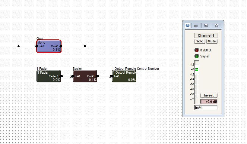
Open each module, including the gain, and set the windows to be able to view all.
In the one output remote control module, choose and enter an available remote control number. Then assign that same control number to the actual fader needing to be controlled.
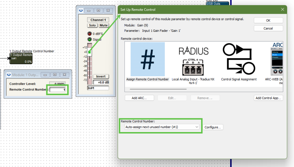
Note the control number output and the gain module fader are the same control number.
Now right-click on the logic fader and set it up to remote control, choosing another available remote control number. Note the chosen control number cannot be the same as the gain fader.
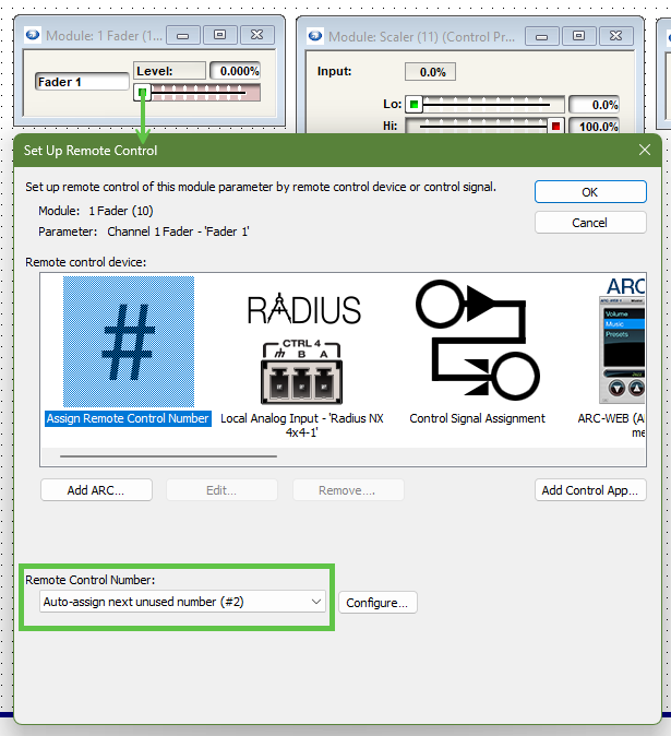
Note the control fader has a different remote control number assignment than the gain module fader.
We can’t see logic activity live while offline. If we push online we will see as we move the control fader from zero to 100% the gain fader moves as well. The point is to limit the effective movement of the gain fader in relation to the full scale movement of the logic fader.
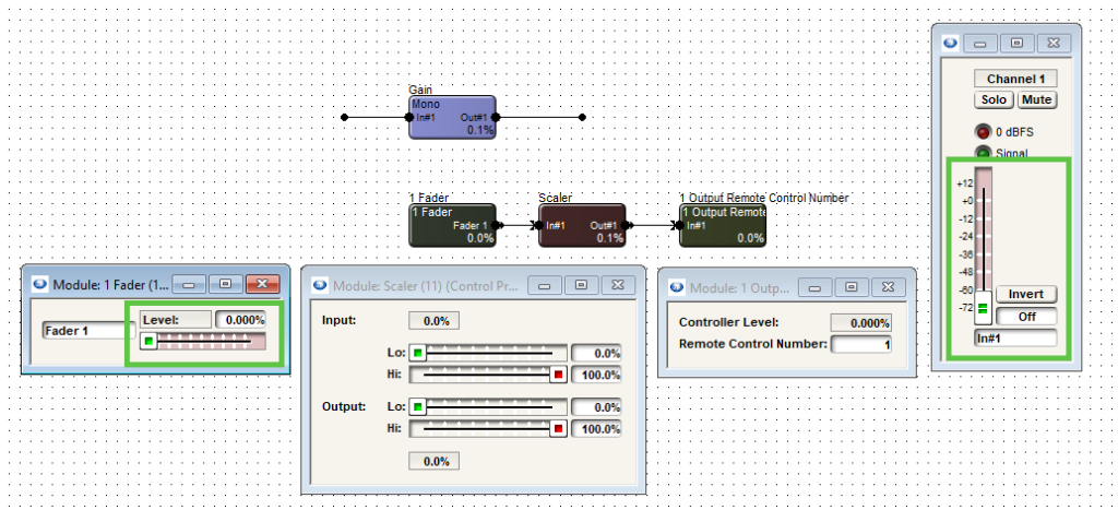
Note when the control fader is at 0% the gain fader is also at the lowest position, “off”.
We can allow the control fader to fully scale on the scaler’s input. But if we adjust the output to a desired degree, we can limit the movement of the gain fader.
limit 1
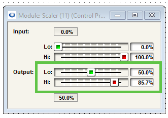
In this case we’ll set the low output to 50% and the high output to 85.7%. This will give us a range of 0 to negative 30 dB.
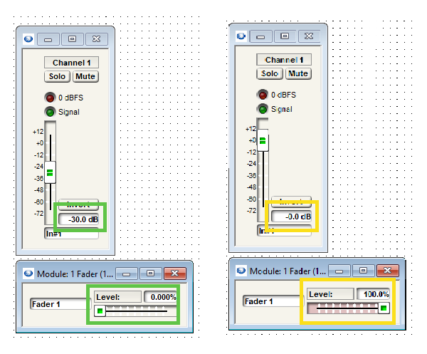
The scaler output values can be adjusted to match requirements of dB range(s).
The control fader is what would be set up for the end user to control in the programming. It in turn controls the gain fader where the actual audio is passing through. Be aware that the representation will be in percentage, not dB.
While the dB level box from the gain module can be set up to remote control for push value, the third-party controller should be consulted about how it will represent this value.
SymVue Control Screens are a powerful and flexible option for system control. This Tech Tip explains how to export a control screen to a T-5 touchscreen, Control Server, and Windows PC.
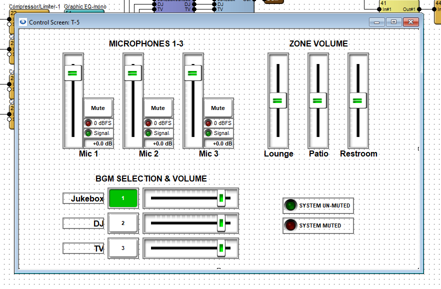
This example is for a three-zone venue with six inputs. User controls should include microphone level control, background music selection and level control, zone volume control, and an indicator if the emergency system mute is engaged.
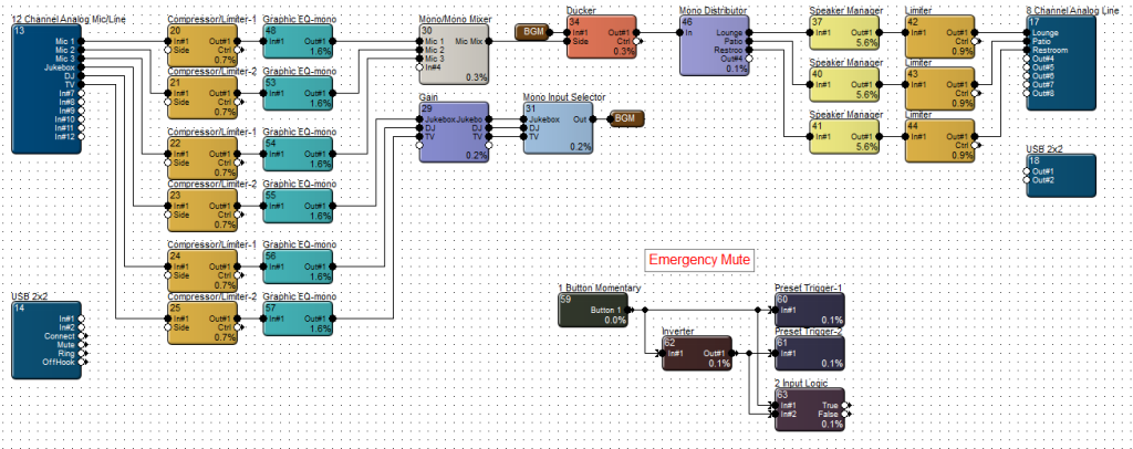
In this example, we will only need to create two control screens; one for the T-5 touchscreen and one that can be used for both Control Server and Windows PC. Once both control screens have been populated with controls and designed according to the available space, open the touchscreen control screen.
T-Series Export:
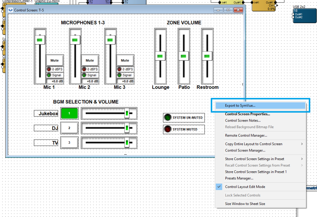
Right click in the background area and select Export to SymVue. Then select Touchscreens and click Next.
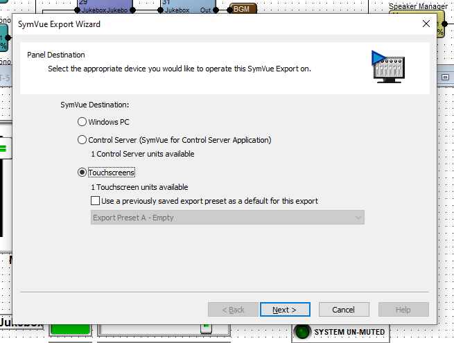
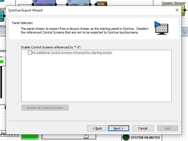
If there are more than one control screen intended for this configuration, this Panel Selection dialogue will allow you to select which screens should be included and referenced by this screen. When preferred selections are made (or if no other control screens are included), click Next.
Note: the “Home” control screen of a configuration is the one that is first exported through right-click > Export to SymVue.
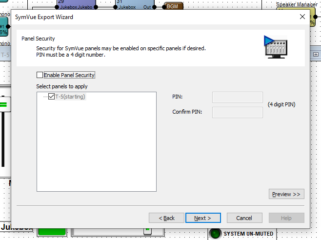
Panel Security allows you to set a PIN code for the desired control screens. This PIN will be used for all selected control screens. Control screens in a given configuration may not have varying PINs.
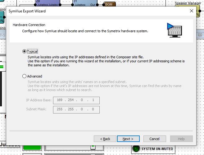
Hardware Connection allows for two options of locating the T-5 touchscreen. Select which is most appropriate for the installation – in the vast majority of cases, Typical is the appropriate selection.
Export Options is the last step. Export to Touchscreens should automatically be checked. The drop down provides options to export this configuration to a specific T-5 or a group of touchscreens.
Note: We strongly suggest selecting “Go Online with Composer site file” to avoid control subscription errors which can be caused by the touchscreen and Composer/DSP not sync’ing parameters.
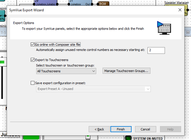
When ready, click Finish. This will export the configuration to the T-5 and push/update the archive on the DSP and go online.
Control Server / Windows PC Export:
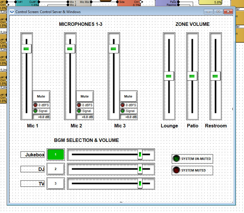
Open the control screen for Control Server and Windows PC. Repeat the steps for T-5 touchscreen, making the appropriate selections for either.
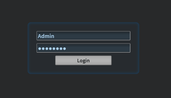
Once the configuration has been exported to Control Server, open up the Control Server’s WEB GUI and log into the Admin account.
Double-click on the Control Server or right-click > open in Site View.
Once viewing the Status page, in the top right corner, go to Menu > Management > Applications and select SymVue from the App list. This will expand the available configurations list.
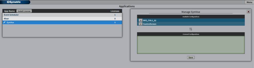
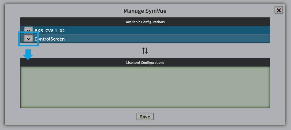
Click the down Arrow (or click and drag) on your control screen – this example “ControlScreen” – and click Save.
Then go to Menu > Management > Users. If you haven’t created a user account for the Control Server, you can do so here. Click on the user that will be accessing the exported configuration.
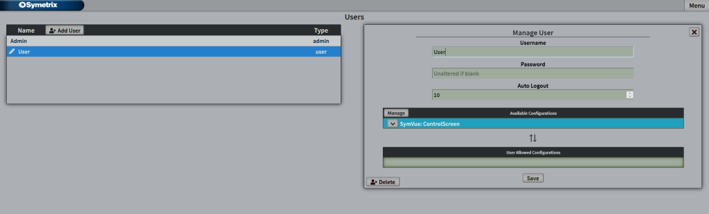
Click on the down arrow for the configuration that this user will access to place it into the User Allows Configurations and click Save.
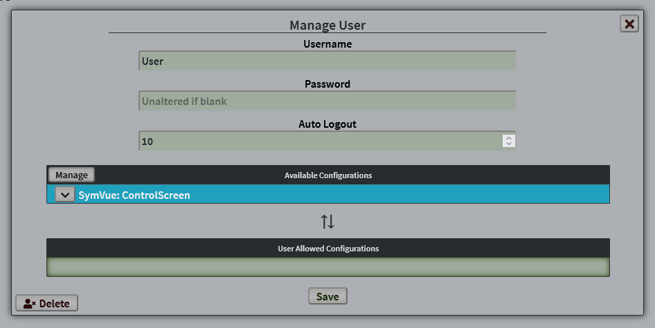
This user now has access to this control screen.
Additional note; Configurations, Licenses, and Applications:
A configuration is any number of single control screens grouped/exported together that act as one “set” of pages or screens. You can have any number of available configurations (sets of control screens) loaded into the Control Server. The number of licensesavailable determines how many of those configurations are allowed to be available to users. You can have any number of users with varying access to any number of the available licensed configurations. Every Control Server comes with 5 licenses, but more can be purchased if necessary.
These control screens are used through the SymVue Application, which is the same medium we use for our export to touchscreen or Windows PC. The Event Scheduler and Mixer apps you may see in Control Server or on export are not related to these control screen configurations.
This is a general-purpose step-by-step guide for connecting to Symetrix digital signal processors and related hardware with a PC.
Please note that Symetrix only recommends using Windows 10 and above. Other operating systems are not officially supported at this time.
See the bottom of this article for information on unsupported equipment and software.
Step 1 – Install the right software for the device
Symetrix design software is used to connect to Symetrix devices and is available to download, install, and run for free. The required software will depend on the devices that needs to be accessed:
COMPOSER PLATFORM:
Software can be downloaded here under the Composer tab.
- D100
- Radius and Radius NX series
- Prism series
- Edge
- Solus NX (note "NX", original Solus are not supported).
- T-Series touch panels
- W-Series wall remotes
- Control Server
- xControl
- xIO Bluetooth
- xIO XLR
- xIn / xOut 4 and 12
- xIO 4x4
- xIO Stage 4x4
Important: To avoid errors when going online with the hardware, please download the version of Composer that matches the DSP’s firmware revision number as closely as possible. This number can be found by cycling through the system pages on the front LCD panel of the DSP.
FIXED ARCHITECTURE PLATFORMS:
Software for Symetrix’s current Integrator Series (closed-architecture) DSPs can be downloaded here under the Jupiter and Zone Mix tabs. These include:
- Jupiter
- Zone Mix 761
Step 2 – Make sure the PC is on the right network
Once the correct software has been downloaded, the next step is to connect the PC to the device’s control network. If a DSP is Dante-enabled, make sure not to confuse the Dante port for the "control"/"ethernet" port. Configuration of these devices through the Symetrix software is always done through the control port.
By default, Symetrix devices are programmed to resolve an IP address automatically, either from a DHCP server or link-local (169.254.x.x) if there is no DHCP server found. Any devices with a front display will indicate their IP address on the front LCD panel. Some devices (T-Series and W-Series) may not show this information if they have been programmed. Cycling through the system pages on the front display of a Composer-based DSP will also display the subnet mask. If a device has previously been configured with a static IP address, it can be reset to DHCP by briefly pressing the device’s reset button, which is usually recessed in the housing on the back of the device.
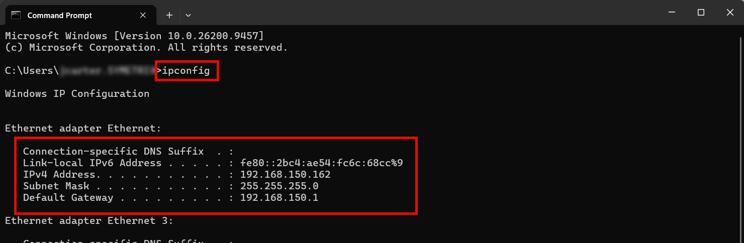
Check your PC's network configuration by opening the Windows Command Prompt and entering "ipconfig". The relevant adapter's information will be shown along with any others available.
Important: Ensure that both the IP address scheme and subnet mask of the PC match that of the DSP. If setting the PC to a static IP address, it must be a different/unused IP address on the network. If connected directly to a DSP that has a known static IP address, setting the PC to any available IP address will work. If connected directly to a DSP that does not have a static IP address, the PC does not need to have a static link local IP address.
Step 3 – Locate the Symetrix hardware on the network and Pull
Once the PC is on the correct network, open the appropriate Symetrix software. The next steps will depend on the software being used.
COMPOSER:
Composer platform devices will show their location status via an indicator on the hardware module itself.
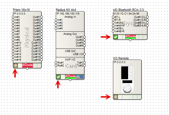
- Devices are located when there is a green check-mark in the location status indicator box.
- If this is empty, the device is not located.
- If the check-mark is yellow, the device is located and its outputs may be muted for some reason.
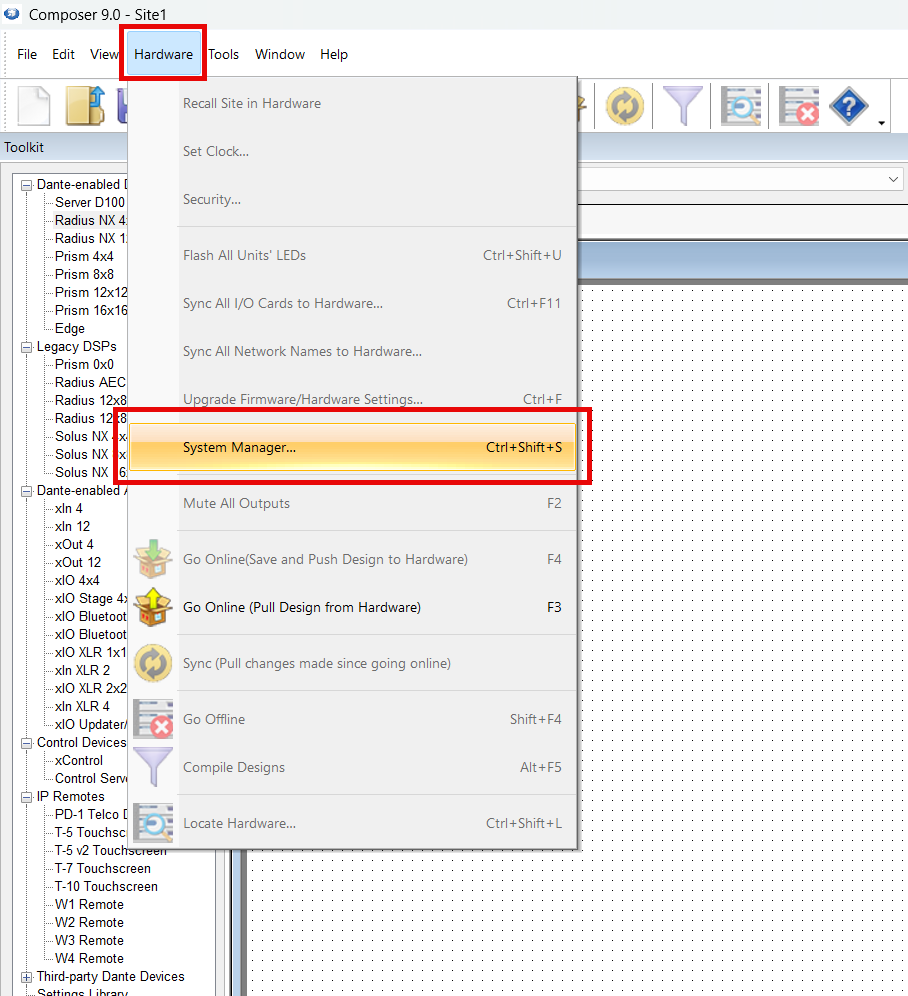
Go to Hardware > System Manager from a blank/new Composer site file to search the network for available hardware.
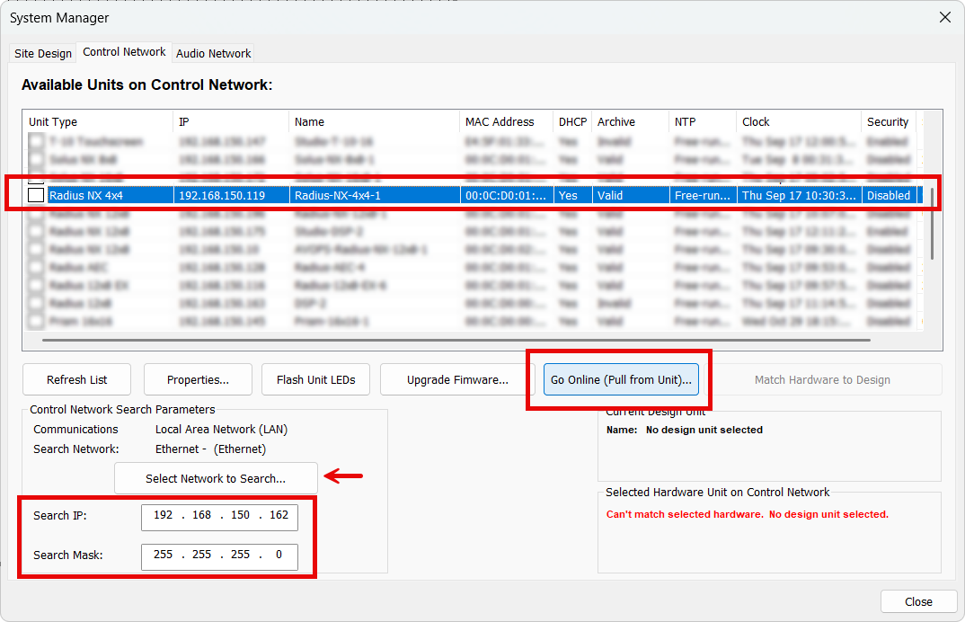
In the Hardware or Control Network tab (depending on the version of Composer) find the appropriate DSP, highlight it, and select Go Online (Pull from Unit).
Note: ensure Composer is using the correct NIC to search the network.
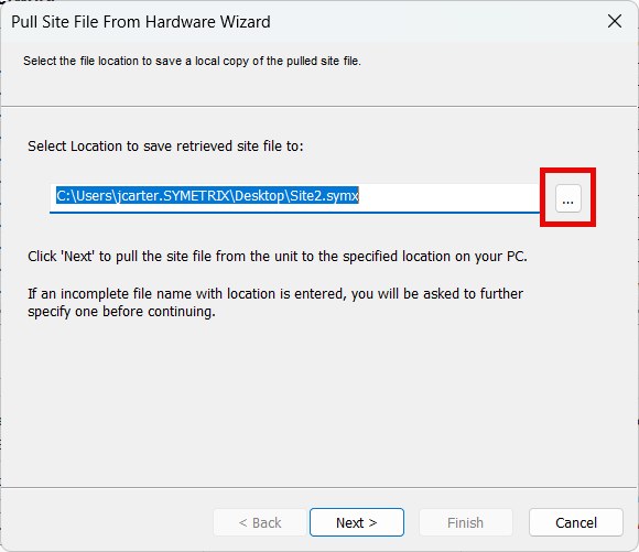
Confirm the file name and save location for the site file - Desktop is a good location, but anywhere that OneDrive or other cloud services don't access is recommended for later permissions and access reasons.
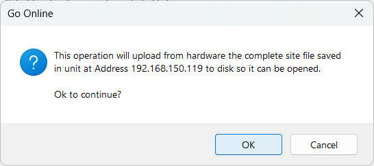
Confirm the prompt that the site file will be pulled from the unit at the given IP address.
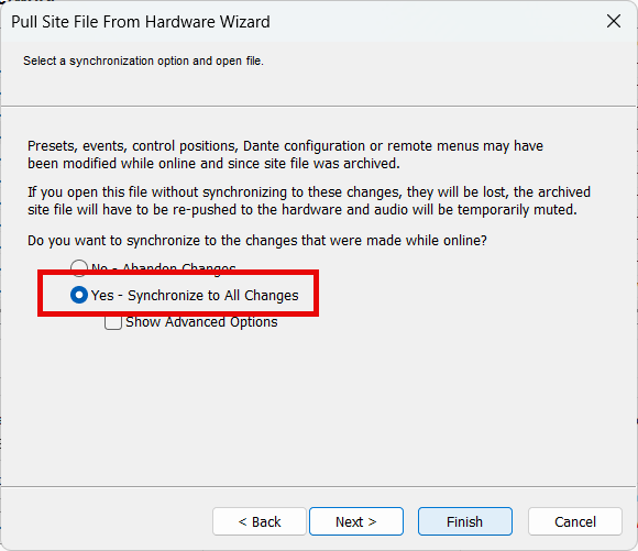
In the large majority of cases, synchronizing the site file on pull is the advisable option. This will pull the current running configuration of all volumes, mutes, routing, etc. - what's running live right now.
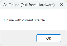
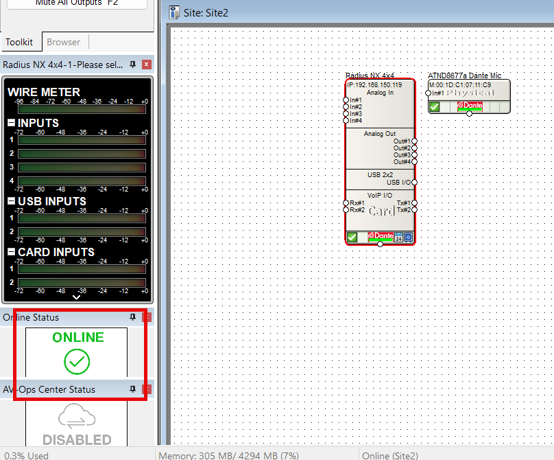
On completion, Composer will notify of Online status with both a dialog and the Online status indicator in the left panel.
FIXED ARCHITECTURE PLATFORMS:
Fixed architecture platforms (Jupiter and Zone Mix 761) will use their own software respectively and have a Connection Wizard to complete location and go online.
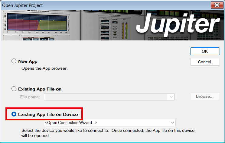
When initially opening the software and connecting to a device select Existing App File on Device to initiate the Pulling process of location and going online.
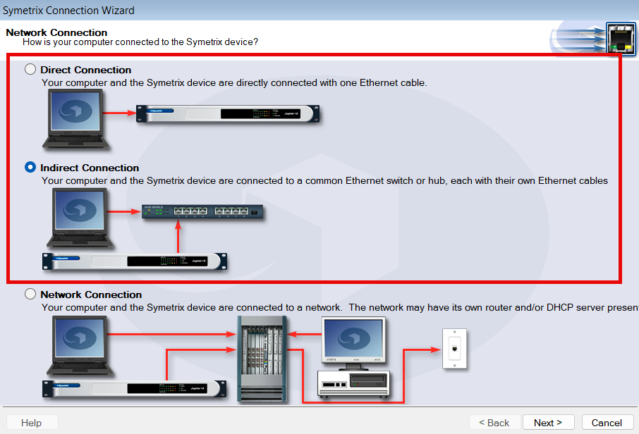
Depending on the connection, select either Direct or Indirect.
- Use Direct if connecting the PC directly cabled to the DSP.
- Use Indirect if using a switch or small network of switches.
- Network is the least common choice and is usually meant for larger networks that involve routing/gateway or subnet jumps (unrecommended).
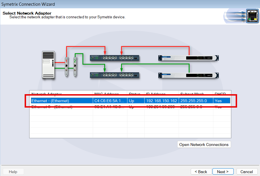
Select the appropriate PC NIC for the connection, if there are multiple available. Wifi should never be used to connect to Symetrix DSPs - always cable to the network or the DSP directly.
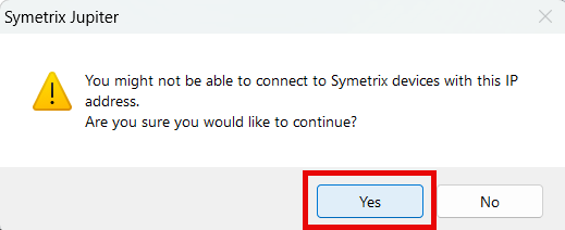
Once a network is selected, the software may warn that it may not be able to connect. This is fairly common and can be clicked Yes through to continue.
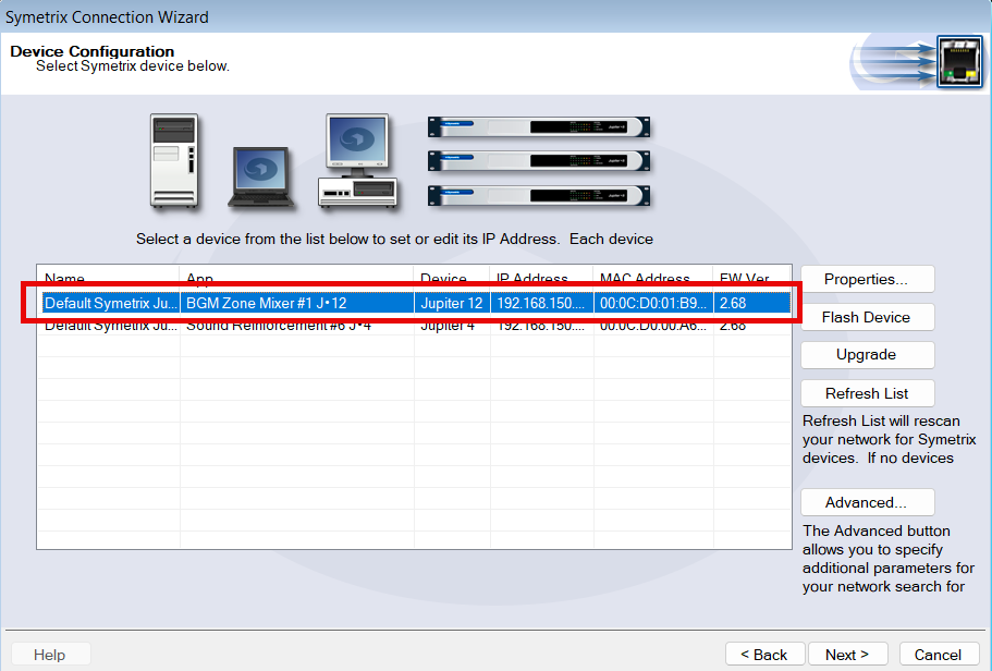
If the PC/software can see the given DSPs on the network, they will be shown here. Select the appropriate one and click Next.
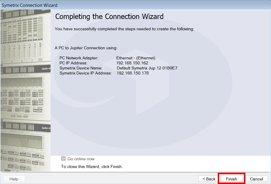
Finalize the Go Online process and the software will attempt to pull the programming and go live.
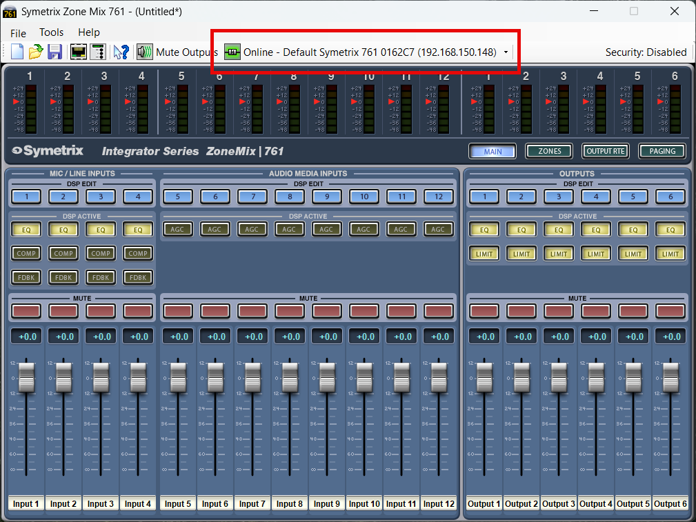
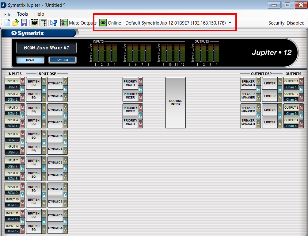
Depending on the software, the main GUI will appear and the "Online" indicator will be present.
Troubleshooting
If you have followed the above steps and are having difficulty locating any devices on the network, we have a location troubleshooting guide available here.
If you are able to locate devices, but are receiving warnings from the software about failures to go online:
- Disable Windows Defender Firewall and any third-party antivirus/firewall programs that may be blocking network traffic.
- Double check that the device firmware versions for all devices in the site file match the version of Composer being used (the first two numbers are most important).
- Power cycle both the PC and the device(s).
- If the device is connected to the PC through a network switch, try connecting directly instead.
- If a (Composer) device cannot be located and is not currently needed in the site file, right click it and select ‘Disable Unit’, then Push online (this will cut audio for the duration of the Push).
- If a specific error code is being presented, please contact Technical Support at support@symetrix.co.
UNSUPPORTED EQUIPMENT
As of January 2024, Symetrix no longer supports the Designer platform, nor any equipment/software released before the Composer platform. This includes, but is not limited to:
Designer platform:
- 8x8 DSP
- BreakIn & BreakOut 12
- CobraLink
- Control I/O
- Express series
- Solus series (not NX)
- ARC-2, ARC-SW4, ARC-K1, ARC-SWK, ARC-Mic/XLR (Note these units do not have "e" at the end while current ARC remotes do.)
Legacy platforms:
- 200 series
- 300 series
- 400 series
- 500 series
- 600 series
- Lucid
- AirTools
- Deuce
- AutoMix Matrix
- Zone Mix 760
- Zone Mix 780
Please contact Technical Support for an archived copy of the Designer software. Other resources may be found online via search engine, message board, or others. We also have a couple of authorized third-party service centers familiar with our legacy equipment and may be able to provide further assistance. Please reach out to:
Condor Electronics
10007 Aurora Ave N
Seattle WA 98133
Phone: 206-633-5190
Email: info@condor-electronics.com
Advanced Musical Electronics
8665 Venice Blvd.
West Los Angeles, CA 90034
Phone: 310-559-3157
E-mail: mail@advancedmusical.com
Any resources, materials, costs, or support for discontinued Symetrix equipment are set solely by these service centers and are not dictated by Symetrix. Symetrix highly recommends upgrading installations with unsupported our outdated equipment to current technology. Please talk to your Regional Sales Manager or Dealer, or locate one through our website per your region here.