


-
Type
- Dante
- Networking
- Control
-
System Management
- Composer Management Software
- SymVue Screen Authoring
- AV-Ops Center Remote Monitoring
- ARC-WEB Control Interface Signal Processing
- D100 AVoIP DSP Server
- Radius NX AVoIP DSP
- Prism AVoIP DSP
- Edge AVoIP DSP
- DSP I/O Expansion Cards
- Jupiter DSP
- Zone Mix 761 DSP I/O Connectivity
- xIO Bluetooth Endpoints
- xIO XLR Endpoints
- xIO AVoIP DSP Audio Expanders Control Systems
- T-Series Touchscreen Controllers
- W-Series Controllers
- Control Server
- xControl GPIO Expander
- ARC-Series Controllers
-
Type
- Dante
- Networking
- Control
-
System Management
- Composer Management Software
- SymVue Screen Authoring
- AV-Ops Center Remote Monitoring
- ARC-WEB Control Interface Signal Processing
- D100 AVoIP DSP Server
- Radius NX AVoIP DSP
- Prism AVoIP DSP
- Edge AVoIP DSP
- DSP I/O Expansion Cards
- Jupiter DSP
- Zone Mix 761 DSP I/O Connectivity
- xIO Bluetooth Endpoints
- xIO XLR Endpoints
- xIO AVoIP DSP Audio Expanders Control Systems
- T-Series Touchscreen Controllers
- W-Series Controllers
- Control Server
- xControl GPIO Expander
- ARC-Series Controllers
DSP I/O Expansion Cards Tech Tips
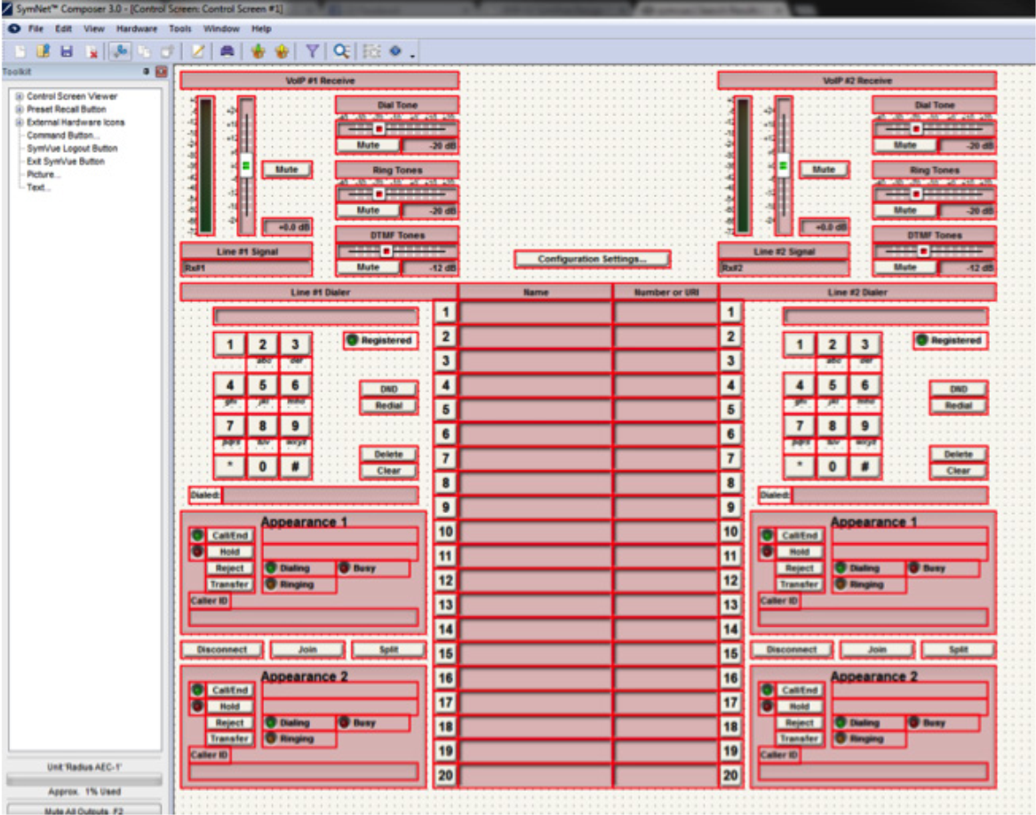
The purpose of this Tech Tip is to provide information on creating SymVue Dialer Control Screens for both the 2 Line Analog Telephone Interface Card and 2 Line VoIP Interface Card. Step by step instructions will be given on how to create the Control Screens and export them to SymVue.
SymVue is a real-time user control panel application that displays Control Screens exported from Composer functioning as a multiuser, multi-point control environment for Symetrix systems.
SymVue runs on any Windows XP or newer compatible device, including touch screen enabled PCs and tablets. The computer communicates directly with Symetrix hardware over a network connection. The desired user control interface is created in Composer as a Control Screen then exported to one or many Windows devices for tailored operation of the Symetrix system.
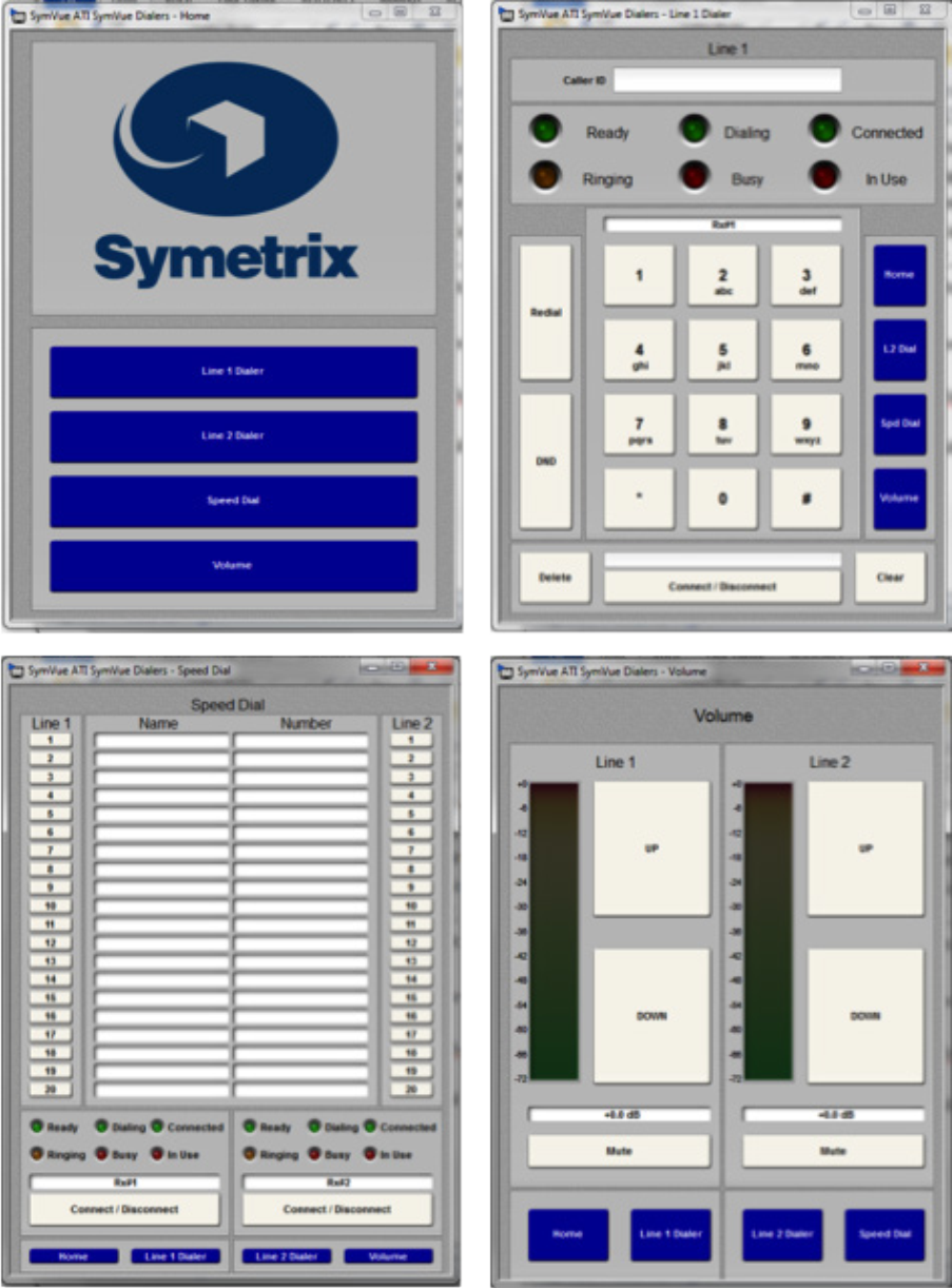
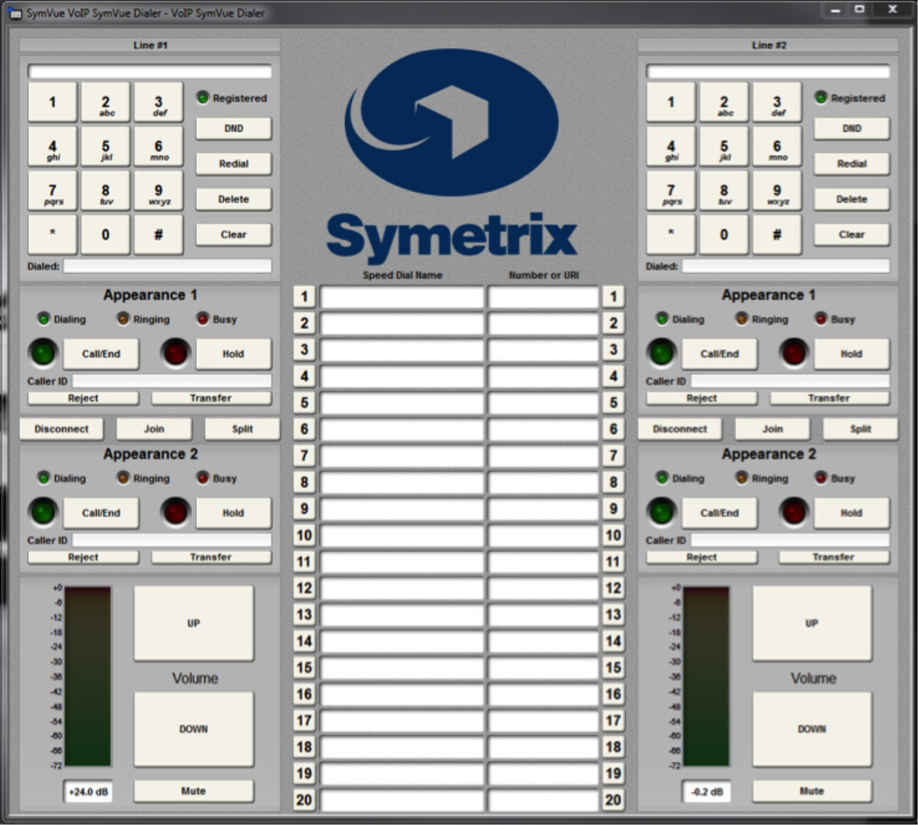
The Input Modules for both the 2 Line Analog Telephone Interface Card (ATI) and 2 Line VoIP Interface Cards can be exported to Control Screens. These Control Screens can be used to provide remote control interfaces (Dialers) for the ATI and/ or VoIP cards without the need or use of complicated 3rd party control systems. SymVue Dialers can be custom tailored to perform any or all of the functionality of the ATI and VoIP modules. These functions can include, but are limited to:
- Detect and answer incoming calls
- DTMF tone dialing
- Speed-dialing (edit and recall)
- Redial
- Do not disturb
- Caller ID
- Call transfer
- Call hold
- Call reject
- Local three-way audio conferencing
- Conferencing and splitting of call appearances
Here are some examples of the different styles of Dialers that can be created:
Instructions
1 Make sure the ATI or VoIP Interface Card has been properly installed into the Radius AEC or Edge Hardware.
install
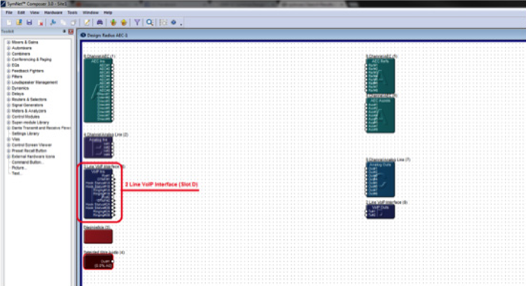
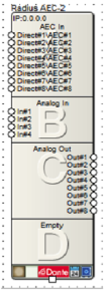
Once the card has been properly installed, the Input Modules will appear on the Design View screen of the site file.
Note: The Input Module will reflect the card slot location (A, B, C, or D). The SymVue Dialer being created will be linked to that specific card slot.
Note: SymVue Dialers can be created without having the ATI or VoIP card installed. Simply right-click the Radius or Edge in the Site View screen of the site file and select “Configure I/O Cards”. Then select the correct card for the specific card slot.
2, Double click and open the Input Module for the ATI or VoIP Interface.
3. Right-click on an open section of the module and select “Copy Entire Layout to Control Screen”.
4. Select “New Control Screen”, unless a Control Screen has already been created and it is being added onto.
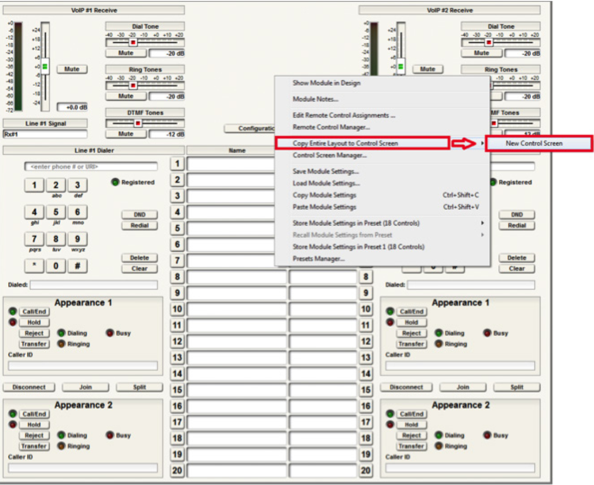
Note: individual pieces can be selected by right-clicking on the desired piece (i.e. button or fader)
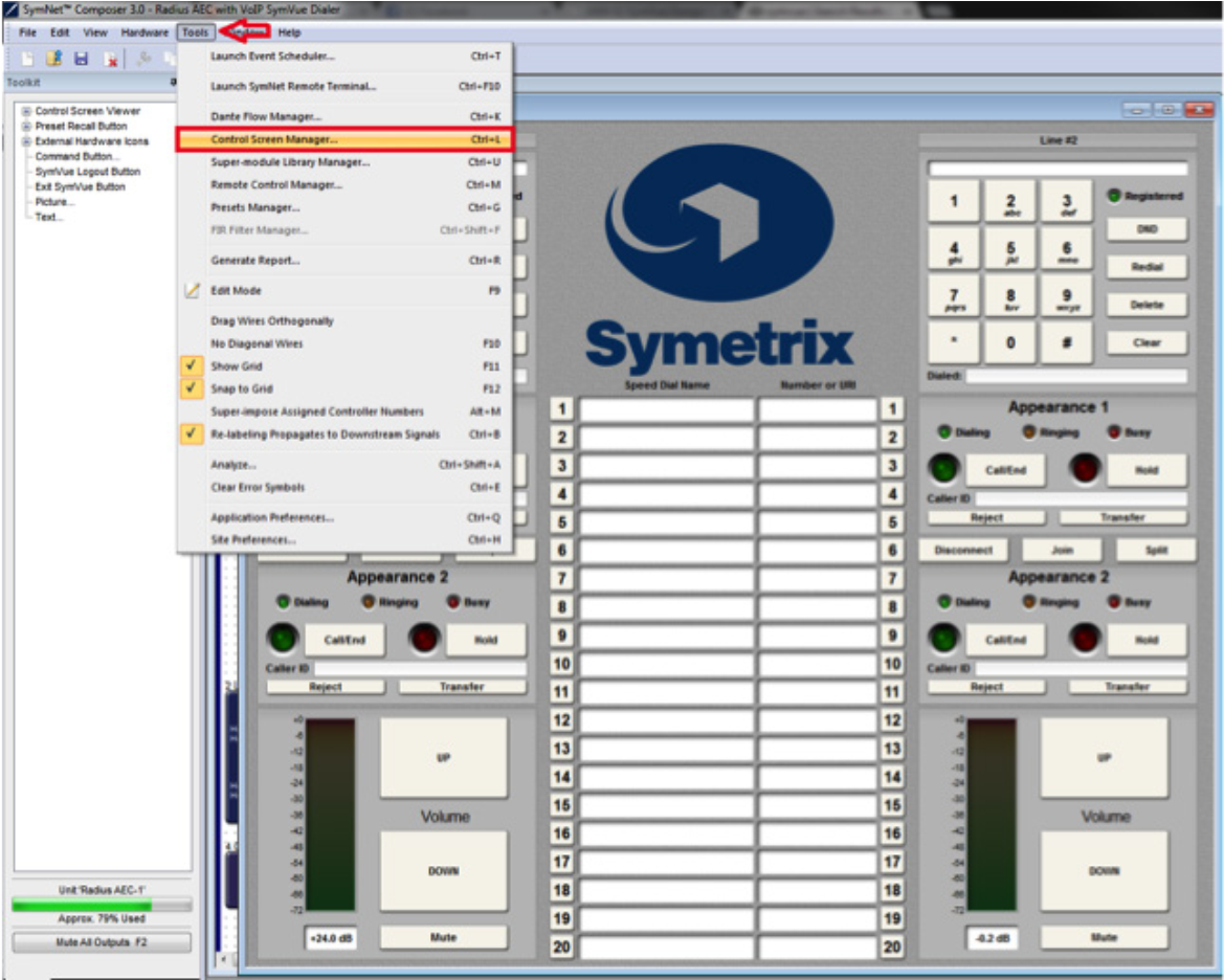
The pre-built example SymVue Dialer has been tailored to use buttons instead of faders for volume control. A “2 Button Momentary” module is used connected to a “Button Ramp” Super Module (available in Super Module Tools folder). The Super Module is then connected to “Output Control Number” modules. The control numbers used by the “Output Control Number” modules are assigned to the volume fader. The “On” buttons for the “2 Button Momentary” module are copied to the control screen.
5. The functions of the Input Module have now been copied to the Control Screen and can now be tailored for specific look and operation.
export
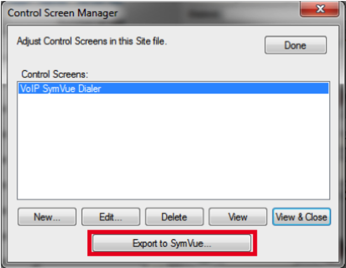
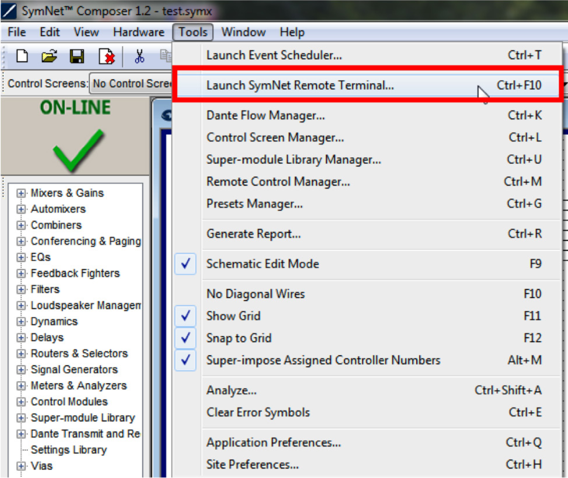
6. Once the Control Screens have been created go to Tools>Control Screen
Manager and export the Control Screens to SymVue.
For additional information on creating SymVue Control Screens click here.
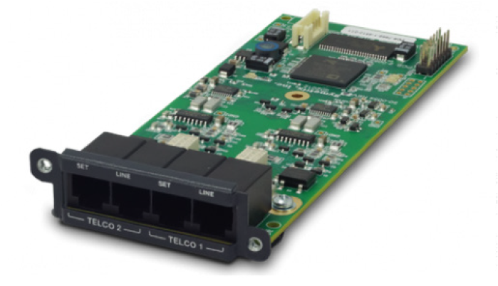
The 2 Line Analog Telephone Interface Card integrates a complete set of PSTN telephony functions into Symetrix conferencing systems. This card provides two analog telephone interface inputs to an EDGE or Radius NX with standard PSTN telephony functions. Up to four of these cards may be installed in a single EDGE for up to eight channels of local input, or one card may be installed into a single Radius NX for up to two channels of local input. Levels, mutes, inversions and formats are controllable via Composer software.
ATI 1
Audio inputs are accessed via rear panel RJ11 (6P6C) connectors. A variety of control options including PSTN telephones, SymVue, and third-party control devices allow intuitive end-user operation and design management. The 2 Line Analog Telephone Interface Card is suitable for a multitude of applications including conferencing, paging, remote monitoring, and broadcast.
Features
- Integrates analog telephone lines into Symetrix conferencing systems. Use up to four cards per Edge, one per Radius NX.
- Standard PSTN telephony functions include:
- Detect and answer incoming calls
- DTMF tone dialing
- Speed-dialing
- Redial
- Do not disturb
- DTMF decoding
- Caller ID reception
- Call progress detection
- Continuous line status and fault monitoring
- Standard RJ11 ports with parallel “set” connections per line for a physical handset, dialer, or ADA compliant visual or audible device connection.
- Field swappable by certified technicians.
- Also suitable for typical audio applications such as paging, broadcast feeds, and remote system monitoring.
Dialers
Standalone dialers can be used in conjunction with the “Set” port on the ATI card for an extremely cost effective solution for end user control. These dialers can be used to provide telephony features such as dialing, redial, onhook / offhook, etc. Listed are a few examples of standalone dialers.
- Accutone T3 Professional Telephone Dialer
- Luminous LH-8001D – Phone Dialer
- Revolabs Tabletop Dialer for Fusion Wireless Microphone System
External controllers (ie, Crestron Pro2) can also be used to control the telephony interface over network (TCP/IP and UDP/IP) control; it does also support serial (RS-232) control. For more information on programming, refer to the Tech Tip for “Crestron Symetrix Dialer Example.”
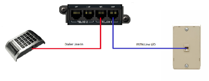
Connecting to the ATI card
- Connect the “Telco 1 – Line” port to the local PSTN wall jack using a standard telephone cord terminated with RJ11 connectors. Optionally, connect a standard analog telephone, dialer, audible and/or visual ringing device, to the “Telco 1 – Set” port of the ATI card. Repeat instructions for “Telco 2” port use.
ATI 2
2. Open Composer and drag an Edge or Radius NX into the configuration. For this example, a Radius NX was used.
ATI 3
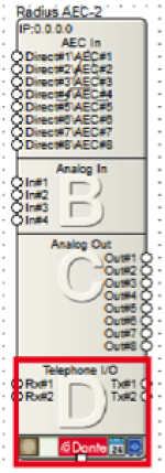
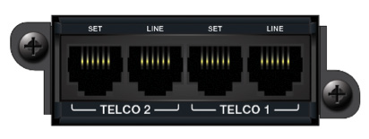
3. Make sure that the bottom box shows “Telephone I/O” with “Rx#1”, “Rx#2” and “Tx#1”, “Tx#2.”
ATI 4
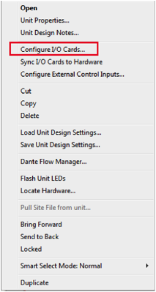
4. If the box does not show “Telephone I/O”, right click and select “Configure I/O Cards…”
5. Select “2 Line Analog Telephone Interface” for Card Slot D, and then click OK.
Note: When setting up an Edge make sure each card slot matches the cards installed into the unit. Each card slot has the following options: No Card Installed, 2 Channel Analog Mic / Line Inputs, 4 Channel Analog Line Outputs, 4 Channel Digital Inputs, 4 Channel Digital Outputs, 4 Channel AEC Inputs, and 2 Line Analog Telephone Interface.
ATI 5
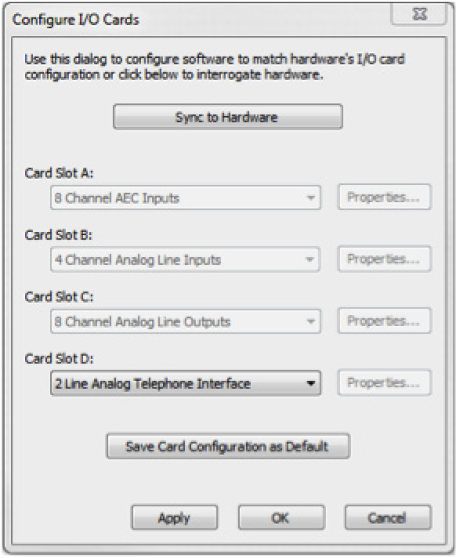
Once the I/O card is added, open the Site File and begin the design.
Overview
With the Two-Line Analog Telephone Interface Card, Symetrix offers a complete conferencing solution within the Composer architecture. The Two-Line Analog Telephone Interface Card (ATI card) is compatible with both the Edge and Radius NX. The Edge is a card-based DSP with four card slots available, allowing it to support up to four ATI cards per unit. Radius NX has one optional card slot available, allowing it to support one ATI card per unit.
Conferencing applications are the most common designs in which the ATI card will be specified; however, there are several other applications that may benefit from the addition of the ATI card and the functionality it provides.
These additional ATI card applications include, but are not limited to:
- Telephone Paging
- Remote System Monitoring
- System Soft Reset
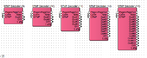
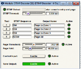
All three of these applications are accomplished by using the ATI card in conjunction with the DTMF Decoder module provided in the Composer Toolkit under ‘Conferencing & Paging’. The DTMF Decoder Module provides a way to trigger logic events in a system using custom DTMF tone sequences from a telephone. Most often the DTMF Decoder will be used to trigger a preset, but it can also be used to trigger any logic function, such as a bell, message player, logic output, etc. In Composer there are 1, 2, 4, 8, and 12 output versions of the DTMF Decoder. When more than 12 DTMF sequences are needed, multiple DTMF Decoders can be used in parallel.
Telephone Paging
line 1
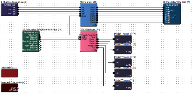
In a paging application, the DTMF Decoder can trigger routing presets based upon DTMF sequences. In the provided example, the DTMF Decoder is set to trigger individual zone paging to zones 1 through 3, with a “Page All” preset also included on the DTMF Decoder output #4. The ATI card Telephone Ins module DTMF output connects to the DTMF input on the DTMF Decoder.
The Hook Status output of the ATI card connects to the CtrlIn (control input) of the DTMF Decoder, which will monitor when the call is ended and then trigger the Off output of the DTMF Decoder. The Off output triggers a preset that will reset the routing matrix so that no zone selections are active between each page.
Remote System Monitoring
Similar to triggering a routing preset for paging applications, a routing preset could be triggered to allow remote monitoring of a system by an event manager, concierge, or integrator under a service contract. This would allow for remotely calling a venue and actively listening in on a current meeting or event. Additionally this solution could be used by a technician for hearing a problem first hand, such as noise or distortion from a speaker or mic that an end user is experiencing, potentially eliminating a long drive to a venue when a problem is related to user error.
System Soft Reset
Many times an audio system is tuned by an integrator or acoustician and the end result is an amazing sounding system. While ideally these tuned parameters would be static so that the audio system will always sounds its best, the end user will need to be able to reconfigure routing, control gains, and mutes, not to mention any other esoteric control functions the end user requires.
As such, sometimes a system ends up in a state, after weeks or months of end user adjustments, in which the end user perceives that the audio system “no longer sounds as good as it once did.” With an ATI card included with the system, some very basic logic can be used to set the entire system back to the tuned “default state” of all parameters without power cycling the hardware. This is known as a “soft reset.”
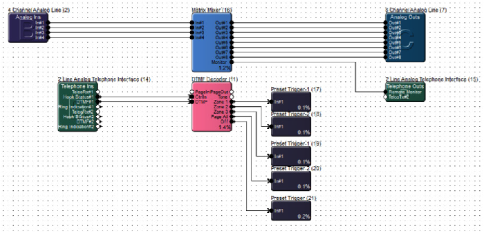
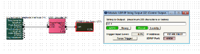
The programming is simple. In a Composer Site File, an ATI Telephone Ins DTMF output connects to a DTMF Decoder. The DTMF Decoder module output connects to a UDP/IP String Output Module or RS-232 String Output module that is used to send a “soft reset” command back to itself. With the UDP/IP String Output Module the command is simply sent to the DSP’s IP address on port 48630. When using a RS-232 String Output module, simply connect the RS-232 phoenix connecter Tx to Rx, such that the command is sent by a DSP to itself. The command to be sent to the DSP for a soft reset is “LC 1” which stands for Load Configuration 1 and will cause the DSP to load the archived Site File. The archived site file is the state of all parameters exactly where they were when the last “Push” was performed from Composer.
This article will demonstrate Composer control logic for automatically hanging up a call if no DTMF signal is received within a period of time. The logic is designed to function with both VoIP and ATI option cards for Radius NX and Edge.
Logic Demonstration
How It Works
There are five key modules used in this design. This section will go through them one by one:
- The Flip-Flop module keeps track of whether or not a DTMF signal has been received from the far end. Normally, the “Set” input would be wired to the “DTMF#1” output of the 2 Line VoIP Interface module, but here it is simulated by a 1 Button Momentary module. The “Reset” input is wired to the “Hook Status#1A” output of the 2 Line VoIP Interface module, with an inverter in between. This will reset the Flip-Flop after the call ends.
- The 2 Input Logic module outputs “True” when the call is active and a DTMF signal has not been received from the caller. Otherwise, the module outputs “False”. The “In#1” input is wired to the “NOT Q” output of the Flip-Flop. The “In#2” input is wired to the “Hook Status#1A” output of the 2 Line VoIP Interface module. The logic type of this module should be set to “AND”.
- The Ramp Processor module takes in the control signal from the “True” output of the 2 Input Logic module and outputs a control signal that ramps up over a specified period of time. Here, it is set to 10 seconds, but this can be set to any desired value. This represents the amount of time the caller will have to enter a DTMF signal before the call automatically hangs up.
- The Threshold Detector module takes in the ramping control signal from the Ramp Processor module, but only outputs a control signal once the ramping control signal reaches 100%. In order to do this, the “Threshold A” value must be set to “100%”.
- The 1 Output Remote Control Number module takes in the control signal from the “True” output of the Threshold Detector module and outputs a high (100%) control signal to Remote Control Number 1. Note that the “Call/End” button in the 2 Line VoIP Interface module has been set up to Remote Control Number 1. This button will be activated when the 1 Output Remote Control Number sends its control signal, ending the call.
Troubleshooting VoIP issues by performing a data packet capture
For VoIP problems that may be experienced when deploying a Symetrix VoIP Interface Card, a useful tool for troubleshooting problems is a network protocol analyzer. Problems are likely taking place on the network or SIP PBX outside of the VoIP Interface Card and a network protocol analyzer allows examination of the communication between the VoIP Interface Card and the VoIP PBX. In most cases, a very short capture of network traffic is enough information for a Symetrix engineer to scrutinize and begin diagnosing a problem. To perform the capture, a computer with a wired Ethernet connection, Wireshark network protocol analyzer software and a managed Ethernet switch with port mirroring are needed.
Installing Wireshark
Start by going to http://www.wireshark.org and clicking on the DOWNLOAD link. Please click the download appropriate for your operating system. Complete the installation process.
Using Wireshark to capture packets
To capture network traffic between the Symetrix VoIP Interface Card and the SIP PBX, a secondary managed Ethernet switch that supports port mirroring will be used. If a secondary managed Ethernet switch is not available, then arrange for a port to be mirrored on the main Ethernet switch that connects back to the SIP PBX.
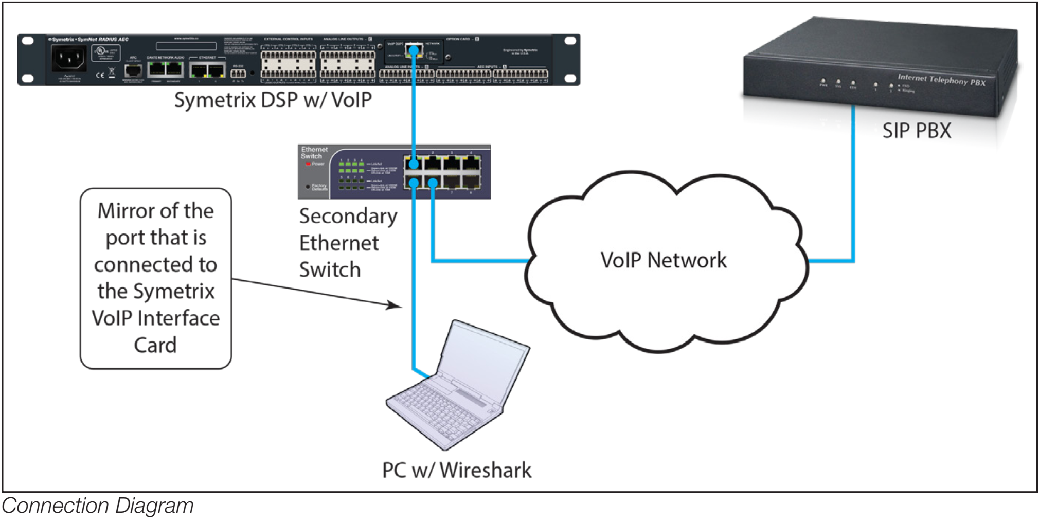
- First setup port mirroring on the managed switch. Port mirroring setup is performed differently for different makes of switches and directions on setting up a mirrored port should be directed to the switch manufacturer
- Connect the computer running Wireshark to the port to which traffic is mirrored.
- Connect the Symetrix VoIP Interface Card to the port of the switch from which traffic is mirrored.
- Connect a port from the main Ethernet switch that connects back to the SIP server to the Ethernet switch being used for the port mirroring.
Proceed to “Capture a Wireshark Trace”
There are just a few more steps to complete before we begin recording network
traffic with Wireshark.
- We recommend closing all other applications at this time, especially any connections to the network. This helps to keep the enormous number of packets recorded to a minimum and makes it simpler to read the traffic.
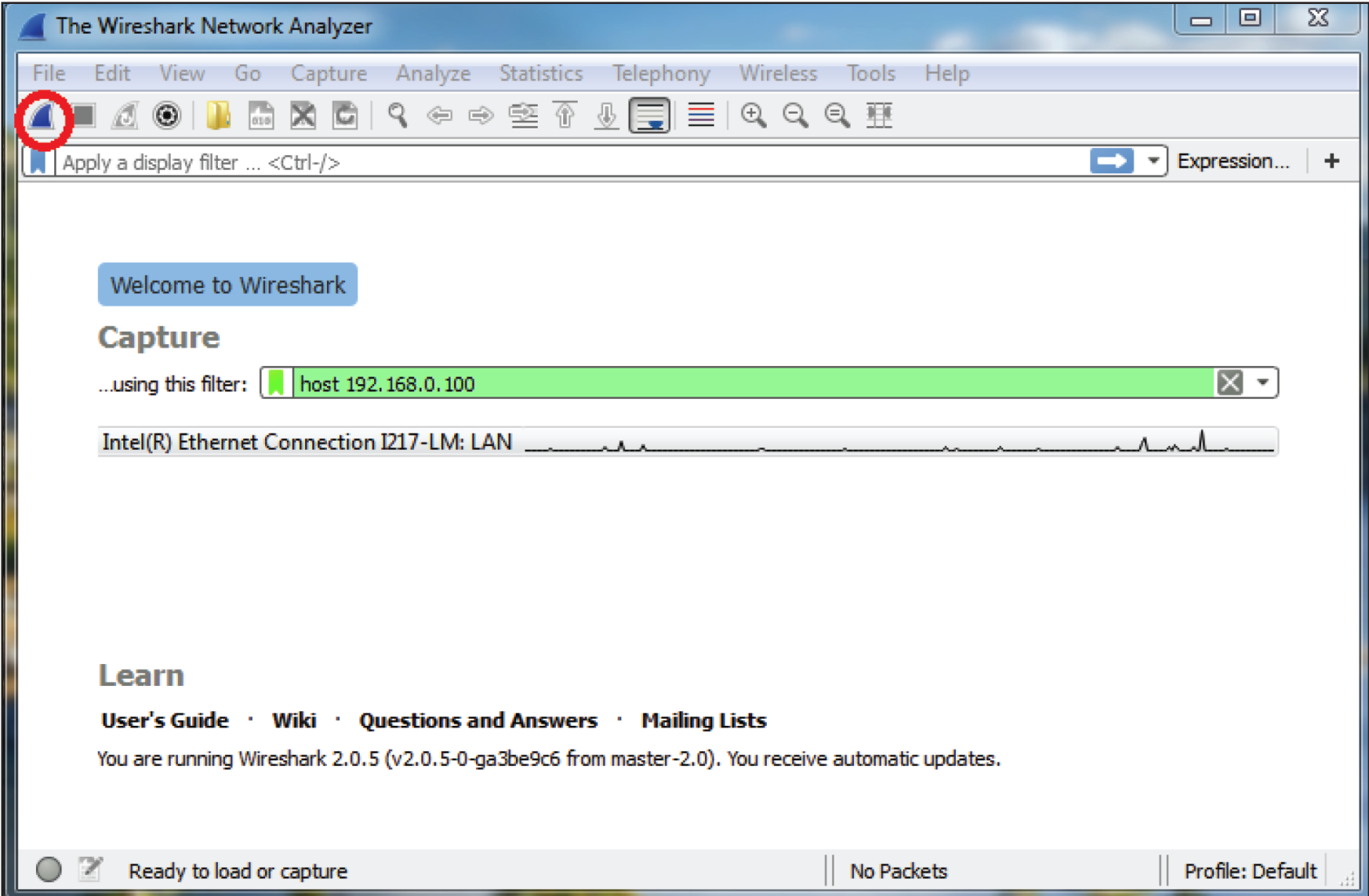
- Wireshark needs to know where to look for packet traffic. At the main window of the Wireshark Network Analyzer, click Capture on the Menu Bar and select Interfaces from the list of options. (Capture > Options: Interface drop-down, promiscuous mode).
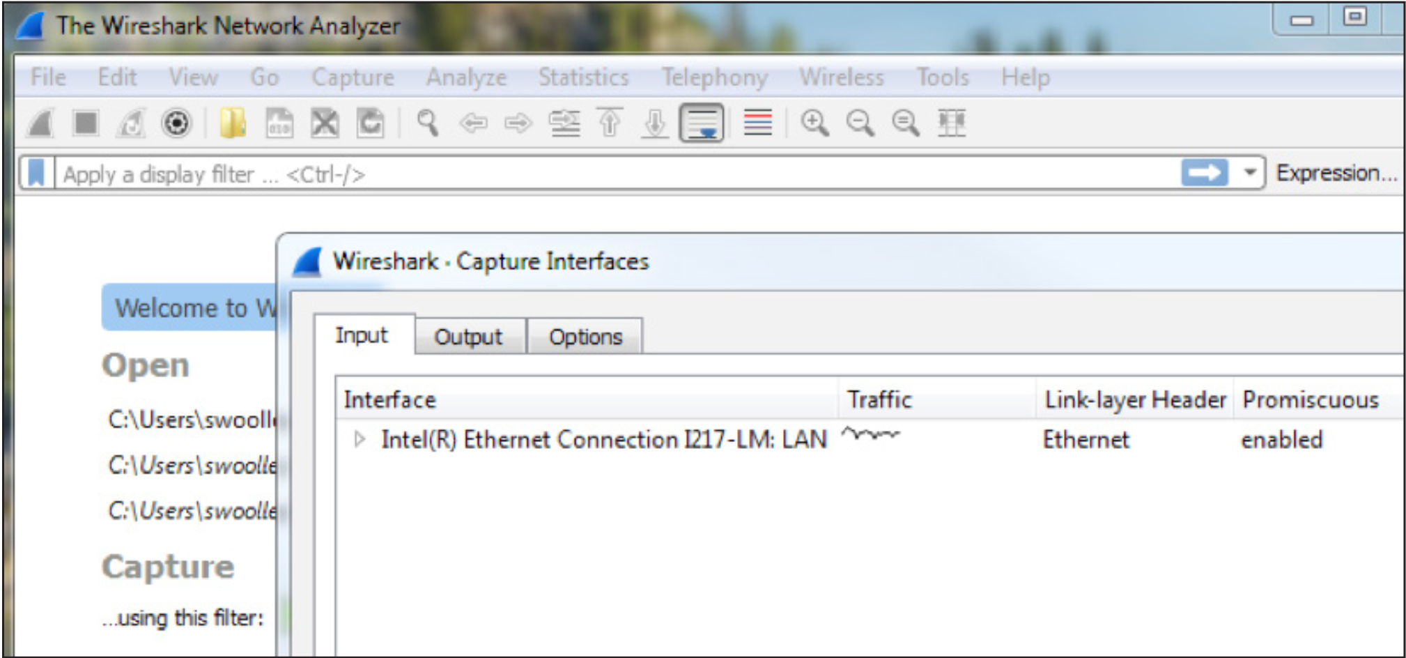
Select the Ethernet card the PC uses as its information access.
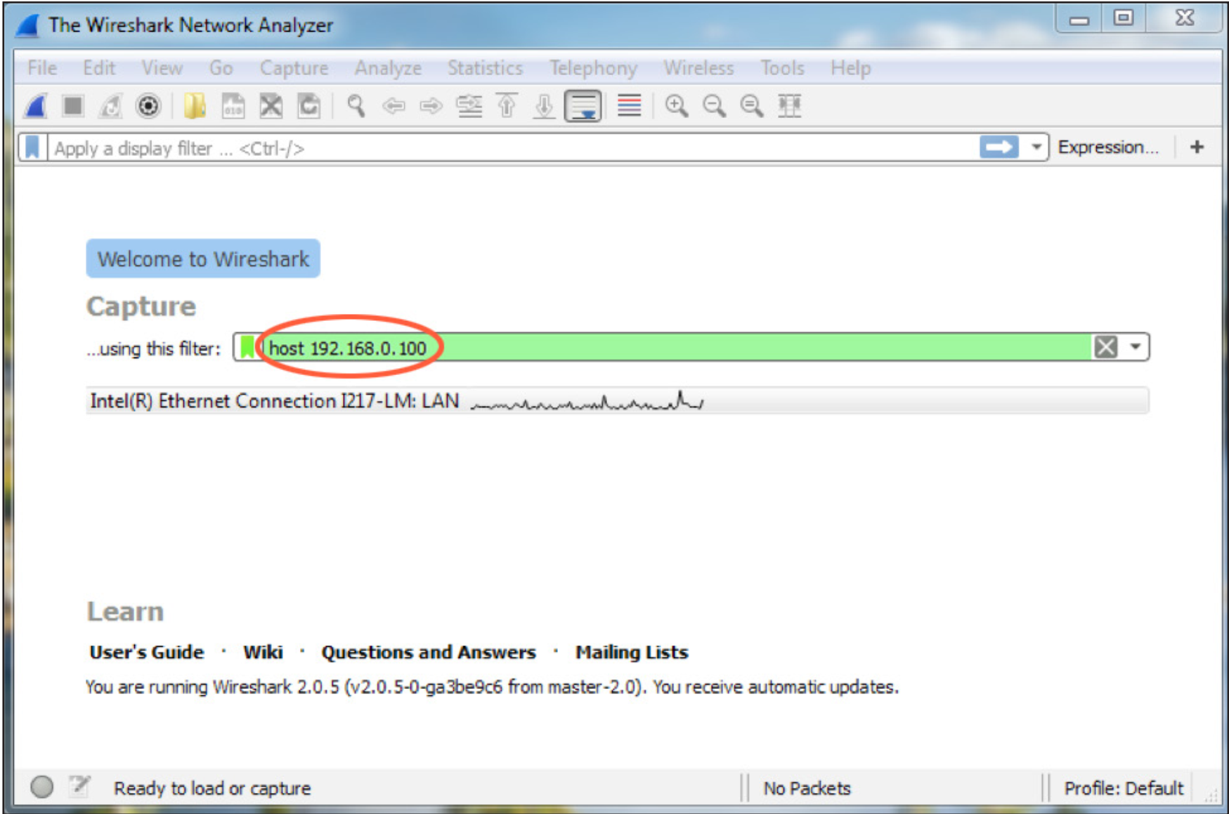
3. Set the capture filter to only capture network traffic to and from the VoIP
Interface Card by typing “host” followed by the IP address of the VoIP Interface
Card in the “Capture …using this filter:” box.
4. Power down the Symetrix DSP which hosts the VoIP Interface Card.
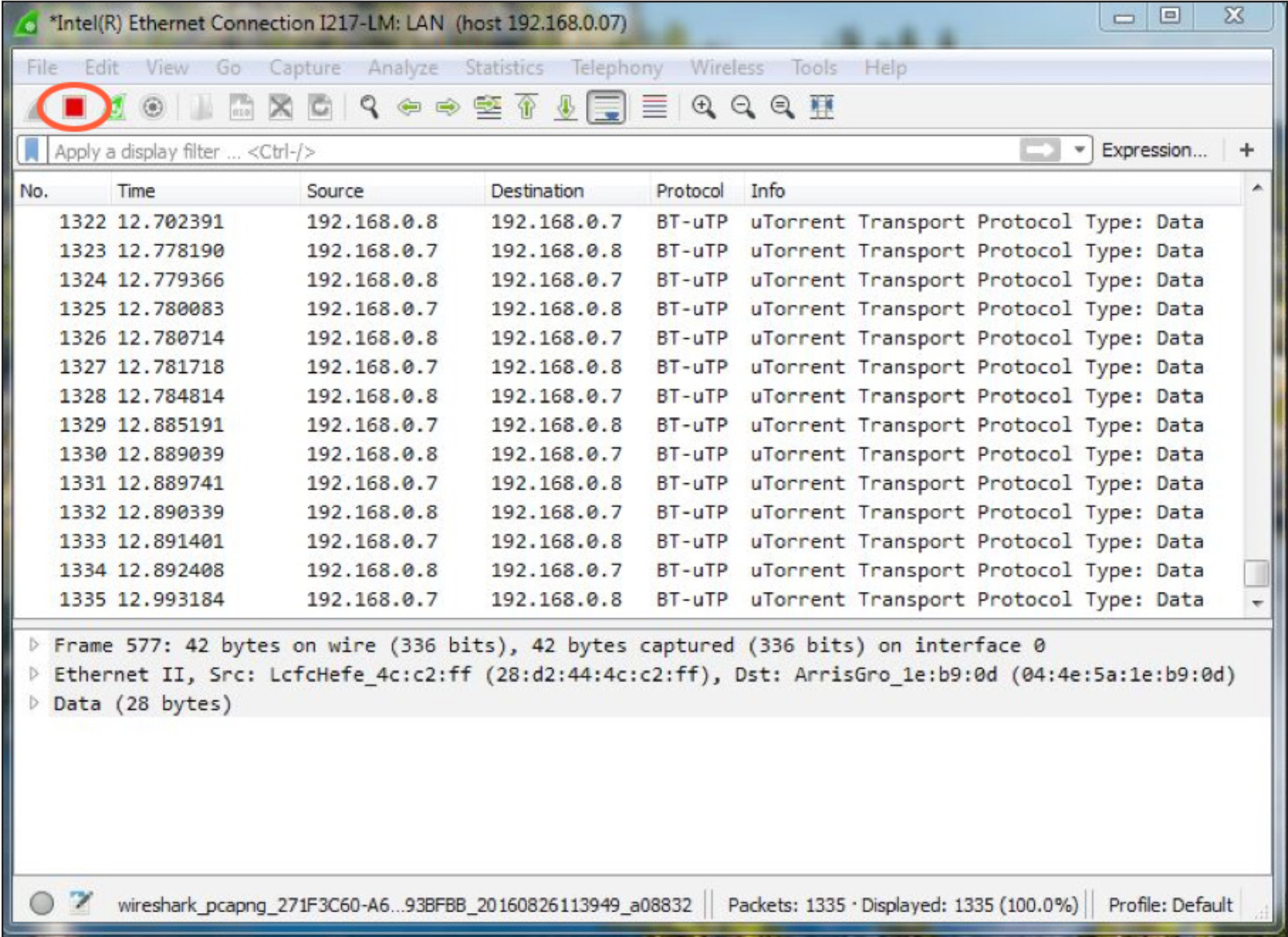
5. Start the Wireshark capture by clicking the Start Capture icon in the Tool Bar
6. Next, power up the DSP and leave the capture running until the DSP has completed boot-up. This will cause the VoIP interface to start the registration process with the SIP PBX.
7. Once the DSP has completed booting, check in Composer and verify if the VoIP interface is registered.
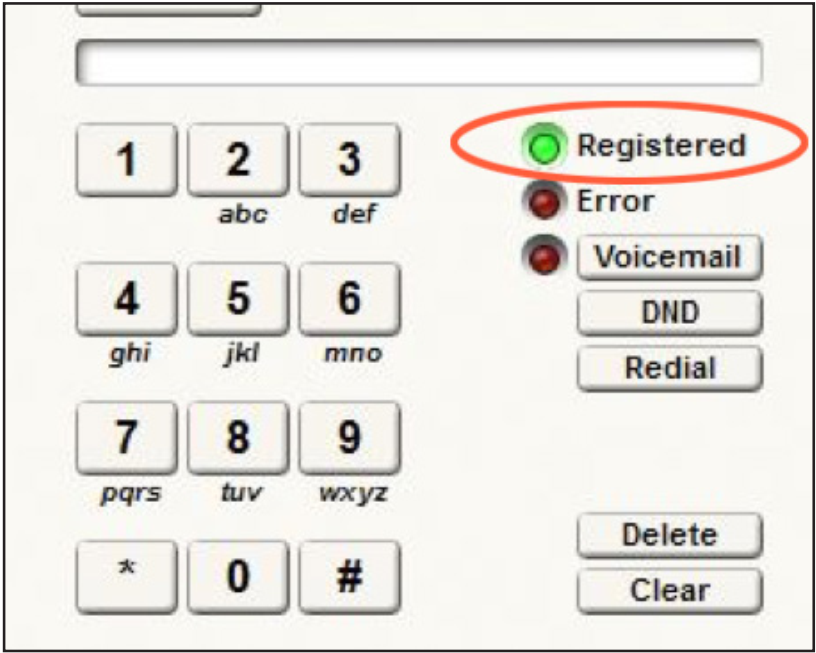
If it is not, stop the capture by clicking the Stop Icon on the Wireshark Tool Bar.
If it is registered, while the capture is still running make a call from the Symetrix DSP to another extension and answer the call at the other extension if it rings. Then hang up the call at the extension. Next, call the Symetrix DSP from another extension and answer the call if it rings. Depending on the problem, additional calls may need to be made for troubleshooting.
8. Once the capture is completed, stop the capture by clicking the Stop Icon on
the Wireshark Tool Bar.
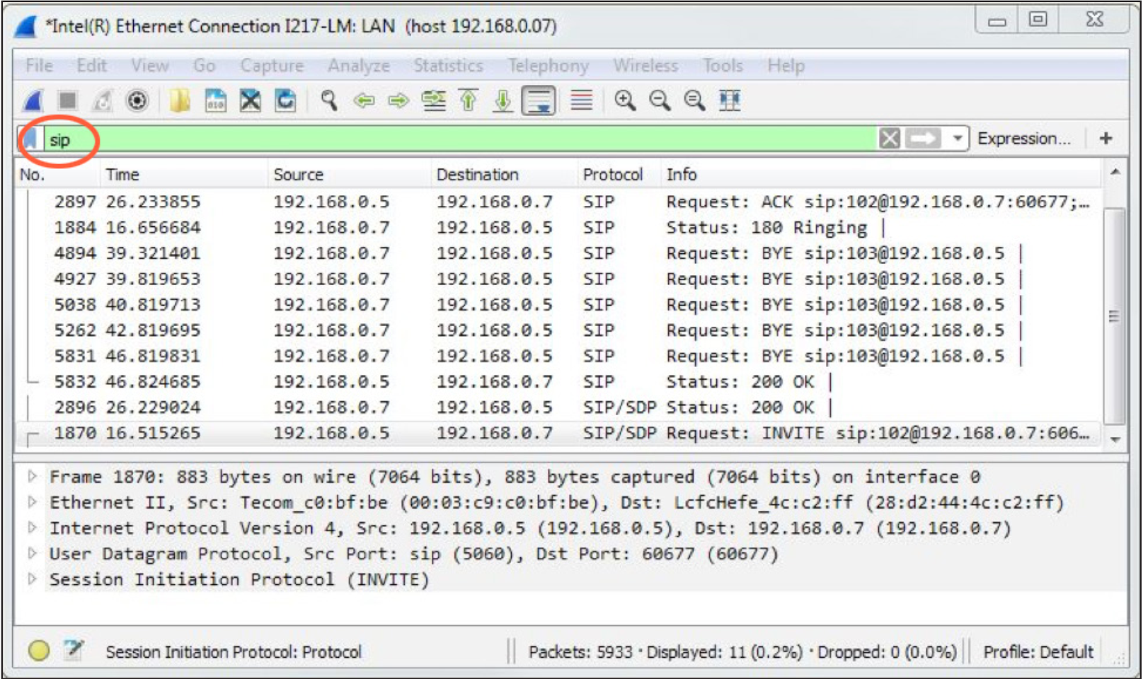
9. Wireshark’s top window should be populating with packet information. Verify
that the data needed has been captured by typing the word “sip” (lowercase) in
the display filter box.
If there are no SIP messages shown, the capture was not correctly performed and will need to be redone once correct capture settings have been set.
10. Once the capture has been stopped, save the information in a file that can be e-mailed to Symetrix. Click on File in the Menu Bar and choose Save from the list of options. When the Save File As dialogue window appears, leave all fields at their default settings (Packet Range information and File Type) and enter a memorable name for the .pcap file. It might be useful to include your company
name or some other unique identifier for association. In addition, make sure you know where this file is being saved so that you can retrieve it for e-mail attachment (the desktop is always easy to find, for example).
That’s it. We are now in a much better position to help you solve any technical difficulties you may be experiencing concerning VoIP troubles related to your Symetrix hardware
This guide provides the detailed steps required to both create an account on a CUCM v9.x with the bare minimum required/recommended settings, and to register a Symetrix 2 Line VoIP Interface card to the CUCM.
Navigating to the CUCM
- Enter the IP address of the server into a browser’s address bar and press
Enter (example: 10.30.0.50) - Click on Cisco Unified Communications Manager
- Type in your Username and Password and select Login.
Preparing the CUCM
Note: : All fields marked with an ‘*’ in CUCM are required for proper setup, some of these fields are set by default
The steps to create a user account and the related phone information are described next
1) Create a Phone Security Profile
a. Select System>Security>Phone Security Profile
b. Click Add New
c. Under Phone Security Profile Type select Third-party SIP Device v(Advanced) and select Next (Basic – single line device)
i. Enter the Security Profile Name under “Name*” (Symetrix VoIP UDP, in this example)
ii. Select the desired Transport Type (UDP in this example)
iii. Check Enable Digest Authentication (we recommend using authentication credentials)
d. Click Save.
2) Create an End User
a. Select User Management>>End User
b. Click Add
i. Create User ID (Symetrix, in this example)
ii. Last Name (Inc. in this example)
iii. Digest Credentials (used for authentication) (12345 in this example)
c. Click Save
3) Create a Phone
a. Select Device>Phone
b. Click Add New
c. From Phone Type, Select Third-party SIP Device (Advanced) and then click Next
d. Device Information box
i. Enter the MAC Address of the Symetrix 2 Line VoIP Interface card, and description (optional, will default to SEP+MAC Address if left blank)
ii. Device Pool = Default
iii. Phone Button Template = Third-party SIP Device (Advanced)
Note: If only a single line registration is required, we may be able to support the Third-party SIP Device (Basic) option.
e. Protocol Specific Information box
i. Device Security Profile = Name of security profile created in step 1)
ii. SIP Profile = Standard SIP Profile
iii. Digest User = End User Created in step 2)
f. Click Save
4) Setup Directory Numbers (DN) for the device (this is the extension number)
a. Click on Line [1] – Add a new DN link on left of page
b. Directory Number Information box
i. Enter a Directory Number (311 in this example)
ii. Enter an Alerting Name (Note: ASCII Alerting Name field will auto fill when this is entered)
c. Line 1 on Device (description given previously) box (Optional)
i. Enter Display (Caller ID) (Note: ASCII Display (Caller ID) field will auto fill when this is entered)
d. Click Save
e. Click GO next to “Related Links: Configure Device (description given previously) to return to the Phone Configuration page
f. Click on Line [2] – Add a new DN link and follow steps b through e above to register the second line on the Symetrix 2 Line VoIP Interface card.
g. Click Save
Registering the Symetrix 2 Line VoIP Interface
Now that the Cisco CUCM is ready for the Symetrix 2 Line VoIP Interface card, it is time to put the appropriate CUCM credentials into the Symetrix Web Admin tool.
1) Setting up Line 1
a. Identification tab
i. Display Name (any display name you want)
ii. User Name (this will be the Directory Number for one of the lines created in CUCM, 311 in this example)
iii. Domain Name (server IP address, 10.30.0.50 in this example)
iv. Local Phone Number (This is the number which a far end would dial to call the card)
b. Server tab
i. Server Name
ii. Server Address (this is the address of the CUCM)*To set up Line 2 follow the same steps as Line 1, but the User Name will be the Directory Number created for the second line of the device in CUCM
Once you’ve installed the Symetrix driver (Symetrix USB Audio v4.14.0 Setup) on your Windows machine and configured the USB Audio Card to run in 8×8 mode, switching to 1×1 modes may result in interrupted audio. After you’ve pushed a 1×1 configuration:
- Navigate to the Windows Control Panel.
- Select Sound.
- On the Playback tab, double-click the Symetrix USB Audio device “Echo Cancelling Speakerphone”
- Select the Advanced tab.
- Ensure that “1 channel 16 bit 48000 (DVD Quality)” is selected for the Default Format. If correct, it will be un-selectable as the above example shows. If the selection is missing the (DVD Quality) tag, click on the correct option in the dropdown menu.
- Select OK to close the USB Card Audio “Echo Cancelling Speakerphone Properties”.
- Repeat steps 3 thru 6 for the Recording tab.
- Select OK to close the Sound menu.
The Digit Map (also called the Dial Plan) defines a collection of digit pattern templates that are used to match valid dial strings, for example 7-digit or 10-digit dialing, as the user enters digits. Once a pattern has been matched, the call is placed using the digits that have been entered. These patterns are used to make it easy for an end-user to dial the requisite digits including internal extensions, emergency numbers and external numbers and have the system dial automatically once the proper number and type of digits have been entered.
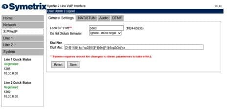
A quick reference can be accessed by placing the pointer of the mouse over the Digit Map field.
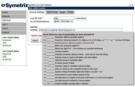
The following table provides a quick summary for all possible Digit Map parameter values.
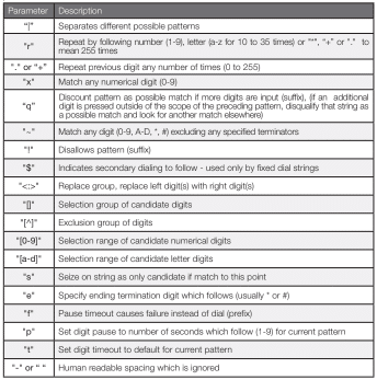
Each of the above parameters, when not used as an informational character, will represent a single digit. This includes if the parameter uses multiple characters for informational reasons.
Below is a detailed view of the default Digit Map:
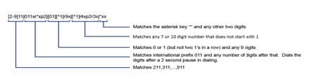
The following examples show how individual patterns are matched:
[3469]11
Allow 311,411, 611 and 911
Each of the items represented in the [] are seen as a single digit. This means “3 or 4 or 6 or 9” plus “11”
1900r7x!
Disallow a 1-900-XXX-XXXX number.
This will tell the system to look at the first four (4) digits of the entered number, and if they match “1900” drop to a failed tone.
976r4!
Disallow a 976-XXXX number from being dialed
This will tell the system to look at the first three digits of the entered number, and if they match “976” drop to a failed tone.
1800r7x
Allow a 1-800-XXX-XXXX number
This will tell the system to look at the first four digits of the entered number, and if they match “1800” dial using 1800 plus the remaining seven digits.
[^1]r6x
Allow a seven digit number not starting with 1, (2XX-XXXX – 9XX-XXXX)
This will tell the system to look at the first digit, if it is a “1” discount the input as a possible match. However if the string starts with any number between “2-9”, then dial using that digit plus the remaining 6 digits.
11[02] Allow 110 and 112
This tells the system to match the digits “11” and either “0” or “2”. For German emergency services, 110 is the Police and 112 is the Fire Brigade.
Some examples for various extensions:
“4xxq” – Matches 3 digit extension beginning with ”4”
“4xxxq” – Matches 4 digit extension beginning with ”4”
“4r4xq” – Matches 5 digit extension beginning with ”4”
“4xxp1xq” – Matches 3 and 4 digit extension beginning with ”4”
“4xxp1xp1xq” – Matches 3, 4, and 5 digit extension beginning with ”4”
The final “q” in the above strings tells the system that if an additional digit is pressed outside of the scope of the preceding pattern, disqualify that string as a possible match and look for another match elsewhere.
1010Se#e*p2r*x
This pattern tells the system to match a “0”, then after pushing a “*” or “#”, allow the user to enter in as many digits as the system can handle, then dial the entire string.
To set up a dial pattern that would allow the user to easily dial between two services, use the <:> symbol. By putting <[89]:> as part of the dial pattern, the system will replace an ”8” or ”9” with a null value, and continue pattern matching as necessary. For example: “<[89]:>r7x”, as long as the first digit is an ”8” or nine ”9”, this pattern will take the set of numbers, remove the first number, and dial out using the remaining seven digits. The user can then put an ”8” as part of the pattern recognition string for one provider, and ”9” as part of the pattern recognition for another provider. This will allow users to easily dial between providers with similar numbers. If one enters two different patterns which could be easily confused, the system will choose the first pattern that is matched. For example, if two patterns, one for eleven digits followed by one for twelve digits, the system will not wait for the twelfth digit, as it will match to the eleven digit pattern first.
Having a general understanding of the AEC module parameters prior to reading this Tech Tip is essential for success during the programming and commissioning stages of the conferencing system. All parameter definitions are covered in the Composer Help file. This Tech Tip outlines some tips and tricks to get great results fast from the Radius NX and 4 Channel AEC Input Card. Keep in mind, room acoustics, mic and speaker placement, and gain structure are the cornerstones of getting the best results in any AEC installation.
Essential Concepts for Successful AEC
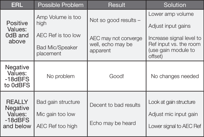
ERL: Echo Return Loss is the difference in signal level between the audio which is present at the reference input and the same audio measured in the room by the microphones. For best results the ERL should be maintained between +/- 10 dB. A 0 dB reading would indicate that the algorithm is working with optimum efficiency.
Reference: The reference should be tapped off the signal path as close as possible to the local reinforcement outputs so that any processing latency, filtering, or delay that are applied to the analog outputs are also applied to the reference input.
Reference Offset: In order for the ERL to be maintained at +/- 10 dB, it is sometimes necessary to offset the level of the audio sent to the reference input at 7-10 dB louder than the same audio entering the microphones. When the room gain is turned up, the level of the far end audio at the microphones is turned up as well. Using a two channel gain module’s master fader for room gain will turn up the reference and the room gain together, maintaining the necessary offset between the reference and the same audio at the microphone input. See Example 1. If the ERL is reading more than +/-10 dB, turn down the speakers in the room or turn the reference signal slightly up using the reference offset gain module.
Example 1: AEC Basic
Notice in this example the reference is tapped off after all dynamics and filtering has been applied to the far end audio. This means the audio at the AEC reference is as acoustically close as possible to the far end audio as it enters the AEC microphones.
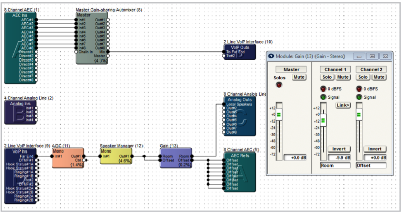
In a best case scenario the room volume would be set to a static operating level tuned for best AEC results. However, if the customer requires level control, you can include a gain module prior to the reference input and room outputs. Remember, the reference should be 7-10 dB louder than the same audio being picked up by the mics from the speakers. In the example above, gain module (13) gives the end user the ability to adjust the room level with the master fader. The individual input 1 and 2 faders create and maintain the 7-10 dB offset between the reference and the room volume. As the end user turns up the room volume, the reference signal also goes up with it.
Example 2: AEC with Local Mic Reinforcement + Mix Minus
The AEC algorithm adds 11 ms of latency which would be distracting if used for the local sound reinforcement. For local reinforcement use the direct outputs of the 4 channel AEC input card instead of the AEC outputs. Each set of outputs should be feeding their own Gain-Sharing Automixer before passing through a matrix mixer, which provides the mix minus capabilities and routing to the local sound and far end.
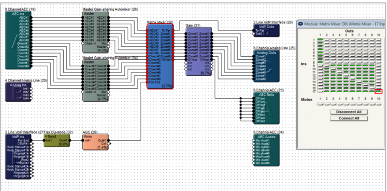
Again, the AEC reference point and local speaker outputs need to be tapped after all processing, and right before the outputs.
Example 3: AEC Dante Flow to Aux inputs (using Shure Dante MXWAPT8 mics)
The Radius AEC and/or SymNet 4 Channel AEC Input card can apply the AEC algorithm to either the analog inputs or any source routed to the AEC Auxes.
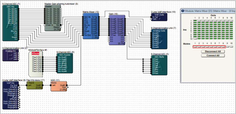
In this example, the AEC is applied to Shure Dante MXWAPT8 mics whose audio enters the SymNet DSP through the Dante bus, while the physical inputs on the AEC Ins module are utilized for additional non-AEC sources via the direct inputs, such as PC audio.
Gain Structure
Follow these steps to set up an AEC Conferencing system with proper gain structure.
- Start with the power amps turned down all the way.
- In the AEC module, adjust the mics input gains so that the meters are showing about -20 dBFS during normal talking level into the mics. Start with the level, and then use the fine trim control.
- Adjust the rest of the gain structure through the entire system for unity gain (-20 dBFS).
- Then establish a connection to the far end, and then slowly bring up the level on the amplifiers, until the appropriate loudness is obtained.
- Adjust the near end mics levels and far end transmit receive levels as required.
- Check the ERL (Echo Return Loss) values. ERL is a measure of how loudly the far end signal is coming out of the near end speaker, and entering the near end mics. This is a visual indication of how hard the AEC process must work to remove echo. ERL will normally be negative; if it is positive or too negative, it may indicate a gain structure problem.
- Once operational, make minor level changes as required, but do not change the level of the amplifiers.
- Engage NLP (Nonlinear Processing) if in a particularly troublesome environment and you still hear echo. Nonlinear processing is useful for removing the secondary indirect echo, often heard as reverb NLP can be very useful and transparent to the participants; however, use of heavy NLP in troublesome environments can reduce double-talk performance and clarity.
- Engage Noise Cancellation if needed to control steady state background noises such as computer fans and HVAC systems.
- Engage AGC (Automatic Gain Control) to compensate for varying distances between the near end participants and their mics. It attempts to maintain a consistent level for better intelligibility.
Troubleshooting Residual Echo:
- Amplifier is turned up too high.
- Mics may be too close to the speakers, or pointed directly towards the speakers
- Input gain on the mics could be set too high.
- Not a high enough signal is being fed to the AEC reference.
- Gain structure is not optimized.
Routing
Here’s a quick reference routing checklist for the site file listing where items should be routed.
- Direct mic inputs are routed to local speakers only.
- AEC mic inputs are routed to the far end only (ATI, VoIP, Codec, etc.).
- Far end inputs are routed to local speakers and refs.
- Audio sources, PC, BGM inputs are routed everywhere (local speakers, far end, and refs).
Troubleshooting
These troubleshooting techniques can be used when implementing an AEC design.
Top reasons for bad AEC result:
- Bad gain structure
- Incorrect mic and speaker placement
- Bad room acoustics
- Local reinforcement is too loud
- ERL showing more than +/-10 dB
- The reference signal tapped off prior to dynamics, filtering, or delay processing
Troubleshooting Residual Echo:
- Verify that the routing to the AEC reference is correct.
- Meter the signal feeding the AEC reference and make sure it is within the recommended range (average -20 dBFS).
- Adjust NLP settings from off to low. If echo is still being heard, switch to high.
- If customer is using an analog phone line. Try removing the Radius AEC from the equation. The use of a “Butt Set” or standard analog phone can help to quickly determine if the echo is being caused with the AEC or on the actual phone system itself. If an analog line is an extension of an IP phone system, the system itself can have an echo. Simply unplug the phone line from the Radius and connect it to the “Butt Set” or standard analog phone. Make a call into the system and out from the system. If you still have an echo, the problem is not within the AEC. If the echo goes away, the problem is within AEC.
The Symetrix 2 Channel Analog Telephone Interface card (ATI card) provides a simple and intuitive solution for audio conferencing applications. Acting as a built-in telephone hybrid, the ATI card provides the means for a Edge or Radius AEC to interface directly with an analog telephone line from the local
telephone company or an analog port from a digital PBX. The graphic user interface for the ATI card within Composer hosts all user controls for dialing a phone number, speed dialing a number, as well as picking up or disconnecting a phone call. The telephony controls are usually accessed by the end user via a SymVue control system or a 3rd party control system.
Crestron and AMX dialer modules have been created and can be downloaded from the Symetrix website. The downloadable folder for each includes the 3rd party dialer module as well as an example Site File:
https://www.symetrix.co/products/audio-io-and-control-expansion/#2-lineanalog-telephone-interface-card
There are two different methods in which a phone number can be dialed using the 2 Channel ATI card
Dialing a Phone Number One Digit at a Time:
When programming a 3rd party control system to dial the ATI card, each digit of the telephone number can be triggered one digit at a time by assigning a controller number to each of the ATI dialer buttons and then triggering them using the CS command outlined in the 3rd party protocol available here: https://www.symetrix.co/?wpdmdl=8
Controller Set Command = CS <Controller Number> <Controller Position> <CR>
The advantage to this method is that no special module need be created to dial the phone number. Instead, each digit on the dialer is treated the same as controlling any button or Boolean control in SymNet with a 3rd party control system.
This means the same control code that turns on or off a mute button can also be used to dial a number button on the ATI card dialer GUI.
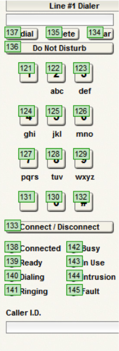
Below is a picture of the ATI card GUI, in Composer, showing the telephone dialer. This picture was taken from the example Site file included with the Crestron and AMX ATI dialer modules. Controller #121 through #133 has been assigned to 1-9,0, *, #, and the connect/disconnect button, respectively.
Best Practice:
In Composer, number the controller numbers on the Dialpad sequentially to make it easier to control
and debug the control strings. Controller numbers can be added by right clicking on the control in Composer and selecting
Edit Remote Control Assignment.
As an example, in order to dial the Symetrix phone number, 1-425-778-7728, the third party control system would send the following commands:
Analog Telephone Interface Dialer
CS 121 65535\r
CS 124 65535\r
CS 122 65535\r
CS 125 65535\r
CS 127 65535\r
CS 127 65535\r
CS 128 65535\r
CS 127 65535\r
CS 127 65535\r
CS 122 65535\r
CS 128 65535\r
After each digit is entered, the Symetrix device will respond with an “ACK” if the command was interpreted correctly or a “NAK” if the controller number does not exist.
After the phone number digits have been entered, the call can be triggered to dial by sending the connect/disconnect button the following command:
CS 133 65535\r
The phone call may be hung up (placed on-hook) by sending the same command again:
CS 133 65535\r
Note: the function of the connect/disconnect button changes depending on if you are connected or
not. Always send 65535 for this value and it will toggle the connect states.
Dial a Phone Number Using a Speed Dial:
Some 3rd party programmers may prefer to create a custom dialing module that sends the entire phone number to the ATI card using a single command string, at which point the phone number can be dialed using a second command that dials the speed dial. The basis of using this two command method is that an ATI card speed dial slot is used as a phone number loading dock, and once the phone number has been loaded into the speed dial location, it can be dialed with a single command.
The ATI card has 20 speed dial locations, so if this method is used one speed dial location must be dedicated to the control system and the end user will 19 remaining speed dial entries.
The command to load the telephone number is the (SSYSS) Set System String command. It is important to note that this command assigns a system string, such as a name or phone number, to one of the speed dial locations and when applicable executing this command will over-write any previous data in the specified speed dial location. Set System String Command =SSYSS <Unit>.<Resource>.<Enum>.<Card>.<Channel>=<Value>
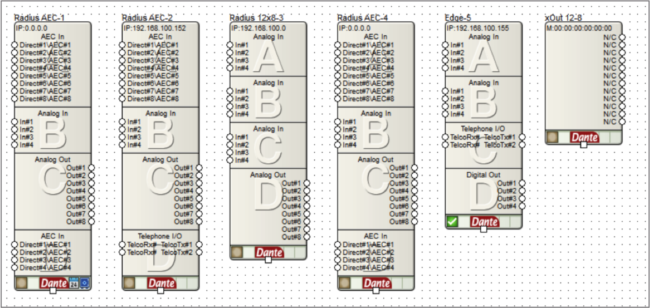
<Unit>=In the site view of the Composer site file, above each unit icon is a number after the dash, e.g. “Edge-1” means =1. (See picture)
<Resource>= 1000 for speed dial number, 1001 for speed dial name.
Some 3rd party programmers may prefer to create a custom dialing module that sends the entire phone number to the ATI card using a single command string, at which point the phone number can be dialed using a second command that dials the speed dial. The basis of using this two command method is that an ATI card speed dial slot is used as a phone number loading dock, and once the phone number has been loaded into the speed dial location, it can be dialed with a single command.
The ATI card has 20 speed dial locations, so if this method is used one speed dial location must be dedicated to the control system and the end user will 19 remaining speed dial entries.
The command to load the telephone number is the (SSYSS) Set System String command. It is important to note that this command assigns a system string, such as a name or phone number, to one of the speed dial locations and when applicable executing this command will over-write any previous data in the specified speed dial location. Set System String Command =SSYSS <Unit>.<Resource>.<Enum>.<Card>.<Channel>=<Value>
<Unit>=In the site view of the Composer site file, above each unit icon is a number after the dash, e.g. “Edge-1” means =1. (See picture)
<Resource>= 1000 for speed dial number, 1001 for speed dial name.
<Enum>= 0 based count of 0-19, where 0-19 equals speed dial slots 1-20.
<Card>= 0 based count of 0-3 for card slots A-D. (A-D in Edge frame, D only in Radius AEC).
<Channel>=Not applicable for the SSYSS command since both ATI ch 1 and 2 share all 20 speed dial locations. Use a zero for this portion of the command.
<Value>= the phone number that should be assigned to the speed dial slot defined by <Enum><Card>
Example of SSYSS:
Notice the ATI card, “Telephone I/O”, in both the Radius AEC-2 and the Edge-5. If the intention is to store the Symetrix phone number into speed dial slot 20 on the Edge-5 unit’s ATI card in card slot C, the command would be determined as follows:
<Unit>=5
<Resource>= 1000
<Enum>= 19
<Card>= 2
<Channel>=0
<Value>= 425-778-7728
SSYSS 5.1000.19.2.0=425-778-7728
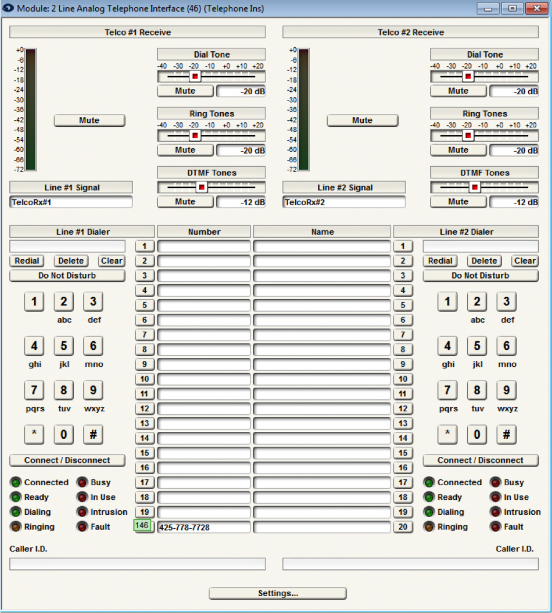
With Composer online with the hardware, the ATI card GUI would show 425-778-7728 in speed dial entry 20:
Then, once the phone number has been loaded into the speed dial entry, the ATI card can be triggered to dial the number by using the CS command to trigger the speed dial location. In the above example controller number 146 is assigned to speed dial #20 location. As such, CS 146 65535\r would dial speed entry 20
As another example, if the intention is to store the Symetrix phone number into speed dial entry 20 on the Radius AEC’s ATI card in card slot D, the commands would be as follows::
<Unit>= 2 (Device is Radius AEC-2)
<Resource>= 1000 (This is for the speed dial entry)
<Enum>= 19 (This is for speed dial 20)
<Card>= 3 (This is for slot D)
<Channel>= 0 (Channel is 0)
<Value>= 425-778-7728
To set the speed dial:
SSYSS 2.1000.19.3.0=425-778-7728\r
To dial the call:
CS 146 65535\r
In review, this two command method can be used to load a phone number into an ATI card speed dial location using the SSYSS command, and then the phone number can be dialed using a single CS command.
Testing the API commands
To help understand the command API, it can be helpful to manually type in commands to control the system. The easiest way to do this is with the built-in Remote Terminal application.
To send a command, type it into the command window as shown in the following figure and press enter to send the string to the device. The command acknowledgments will appear in the window below.