


-
Type
- Dante
- Networking
- Control
-
System Management
- Composer Management Software
- SymVue Screen Authoring
- AV-Ops Center Remote Monitoring
- ARC-WEB Control Interface Signal Processing
- D100 AVoIP DSP Server
- Radius NX AVoIP DSP
- Prism AVoIP DSP
- Edge AVoIP DSP
- DSP I/O Expansion Cards
- Jupiter DSP
- Zone Mix 761 DSP I/O Connectivity
- xIO Bluetooth Endpoints
- xIO XLR Endpoints
- xIO AVoIP DSP Audio Expanders Control Systems
- T-Series Touchscreen Controllers
- W-Series Controllers
- Control Server
- xControl GPIO Expander
- ARC-Series Controllers
-
Type
- Dante
- Networking
- Control
-
System Management
- Composer Management Software
- SymVue Screen Authoring
- AV-Ops Center Remote Monitoring
- ARC-WEB Control Interface Signal Processing
- D100 AVoIP DSP Server
- Radius NX AVoIP DSP
- Prism AVoIP DSP
- Edge AVoIP DSP
- DSP I/O Expansion Cards
- Jupiter DSP
- Zone Mix 761 DSP I/O Connectivity
- xIO Bluetooth Endpoints
- xIO XLR Endpoints
- xIO AVoIP DSP Audio Expanders Control Systems
- T-Series Touchscreen Controllers
- W-Series Controllers
- Control Server
- xControl GPIO Expander
- ARC-Series Controllers
SymVue Screen Authoring Tech Tips
The purpose of this Tech Tip is to provide information on creating SymVue Dialer Control Screens for both the 2 Line Analog Telephone Interface Card and 2 Line VoIP Interface Card. Step by step instructions will be given on how to create the Control Screens and export them to SymVue.
SymVue is a real-time user control panel application that displays Control Screens exported from Composer functioning as a multiuser, multi-point control environment for Symetrix systems.
SymVue runs on any Windows XP or newer compatible device, including touch screen enabled PCs and tablets. The computer communicates directly with Symetrix hardware over a network connection. The desired user control interface is created in Composer as a Control Screen then exported to one or many Windows devices for tailored operation of the Symetrix system.
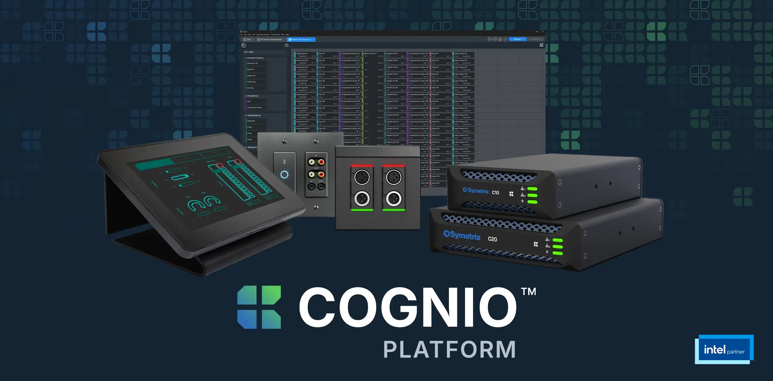
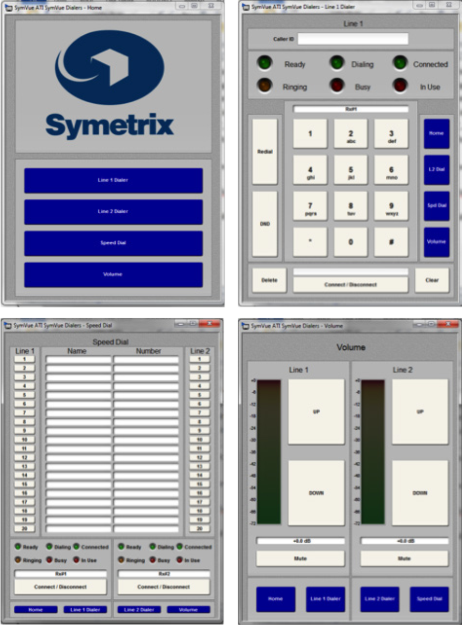
The Input Modules for both the 2 Line Analog Telephone Interface Card (ATI) and 2 Line VoIP Interface Cards can be exported to Control Screens. These Control Screens can be used to provide remote control interfaces (Dialers) for the ATI and/ or VoIP cards without the need or use of complicated 3rd party control systems. SymVue Dialers can be custom tailored to perform any or all of the functionality of the ATI and VoIP modules. These functions can include, but are limited to:
- Detect and answer incoming calls
- DTMF tone dialing
- Speed-dialing (edit and recall)
- Redial
- Do not disturb
- Caller ID
- Call transfer
- Call hold
- Call reject
- Local three-way audio conferencing
- Conferencing and splitting of call appearances
Here are some examples of the different styles of Dialers that can be created:
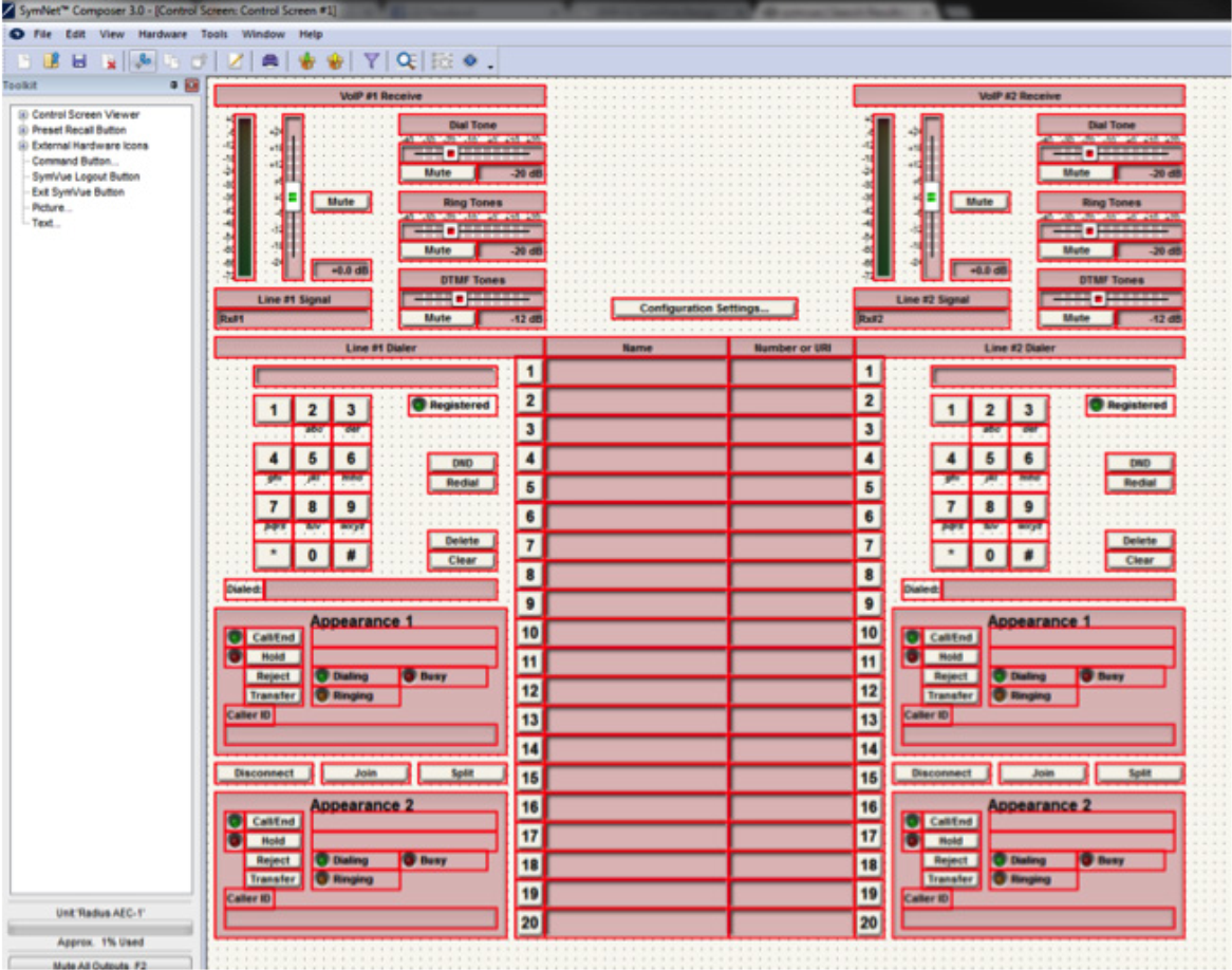
Instructions
1 Make sure the ATI or VoIP Interface Card has been properly installed into the Radius AEC or Edge Hardware.
install
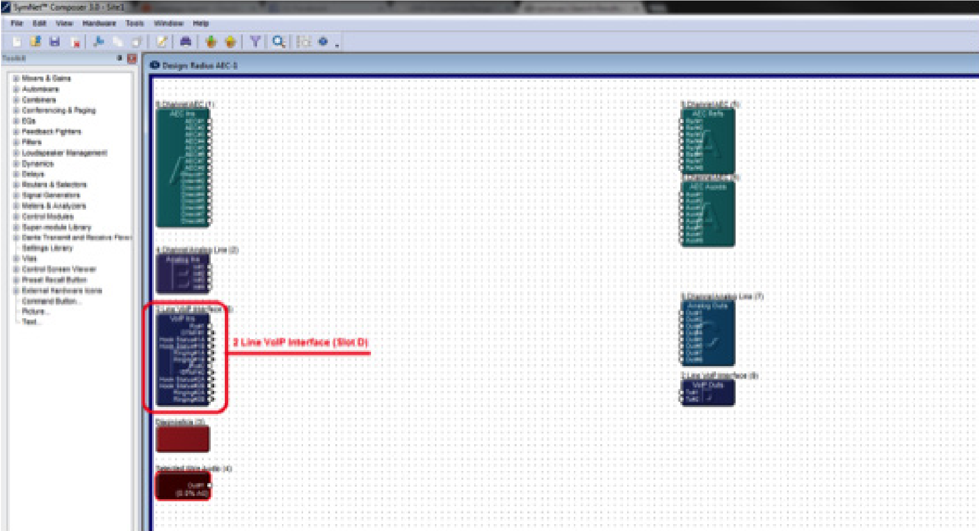
Once the card has been properly installed, the Input Modules will appear on the Design View screen of the site file.
Note: The Input Module will reflect the card slot location (A, B, C, or D). The SymVue Dialer being created will be linked to that specific card slot.
Note: SymVue Dialers can be created without having the ATI or VoIP card installed. Simply right-click the Radius or Edge in the Site View screen of the site file and select “Configure I/O Cards”. Then select the correct card for the specific card slot.
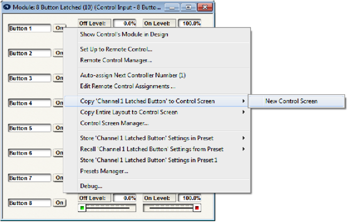
2, Double click and open the Input Module for the ATI or VoIP Interface.
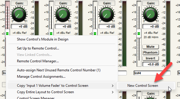
3. Right-click on an open section of the module and select “Copy Entire Layout to Control Screen”.
4. Select “New Control Screen”, unless a Control Screen has already been created and it is being added onto.
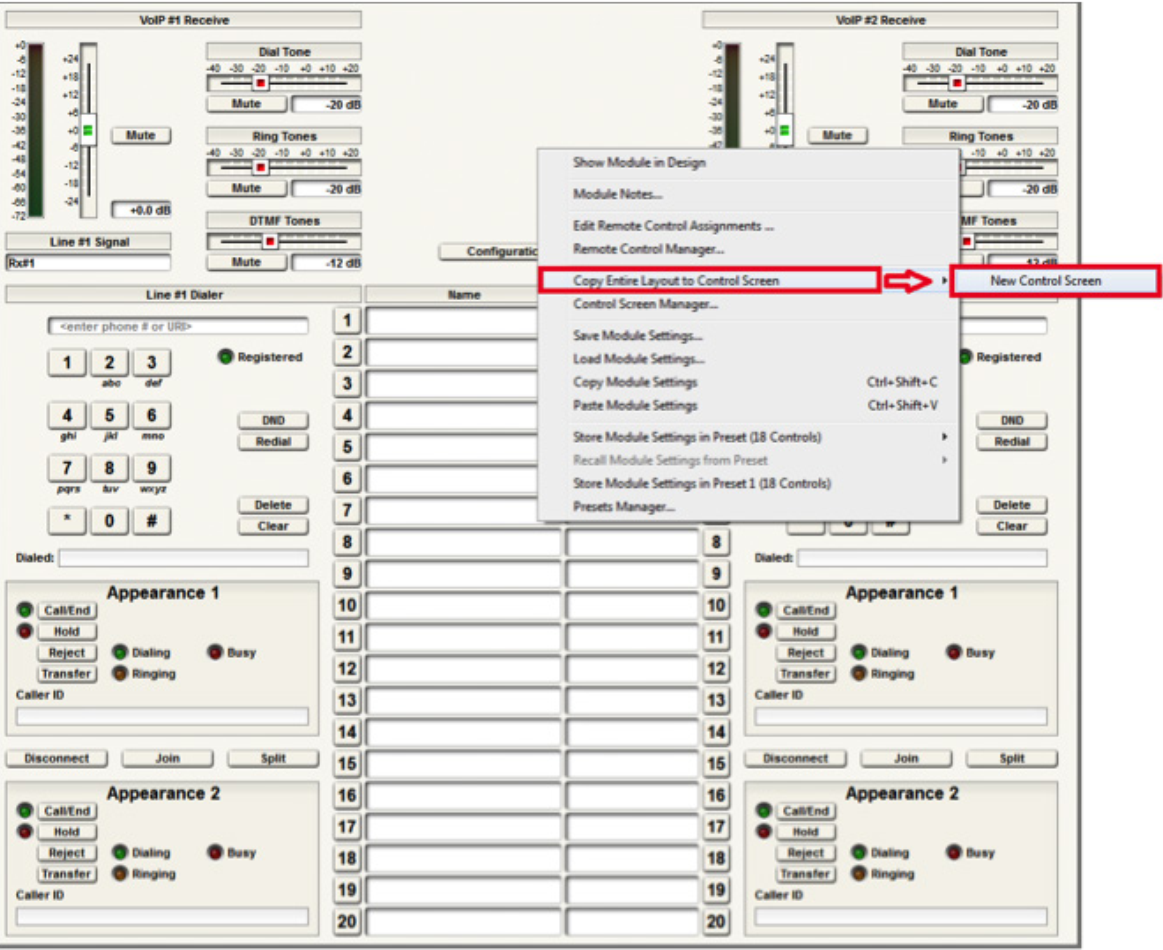
Note: individual pieces can be selected by right-clicking on the desired piece (i.e. button or fader)
The pre-built example SymVue Dialer has been tailored to use buttons instead of faders for volume control. A “2 Button Momentary” module is used connected to a “Button Ramp” Super Module (available in Super Module Tools folder). The Super Module is then connected to “Output Control Number” modules. The control numbers used by the “Output Control Number” modules are assigned to the volume fader. The “On” buttons for the “2 Button Momentary” module are copied to the control screen.
5. The functions of the Input Module have now been copied to the Control Screen and can now be tailored for specific look and operation.
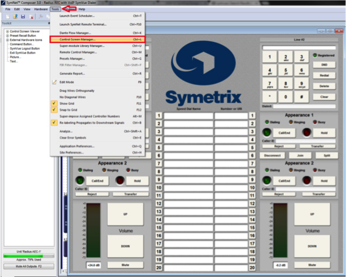
export
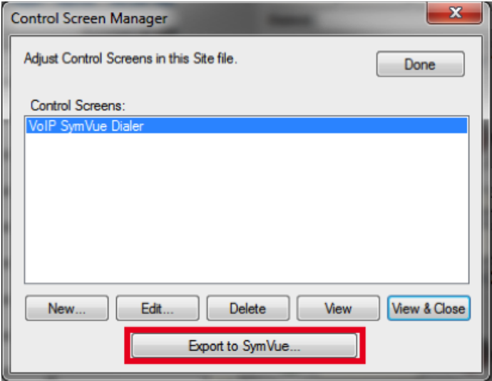
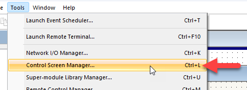
6. Once the Control Screens have been created go to Tools>Control Screen
Manager and export the Control Screens to SymVue.
For additional information on creating SymVue Control Screens click here.
Due to the inherent nature of touchscreens, the use of momentary buttons on control screens in SymVue may result in some unexpected behavior – when the user touches a button on the screen, the “on” action isn’t sent to the DSP until the user actually releases their finger from the button. This can make the use of momentary buttons somewhat confusing for the end-user, in that a swiping action is required to trigger them on touchscreens. For some users, simply letting them know that a “swiping action” is required is good enough. For others, a workaround may be needed to give them expected touch functionality. Fortunately, this default touchscreen behavior does play nicely with latching buttons.
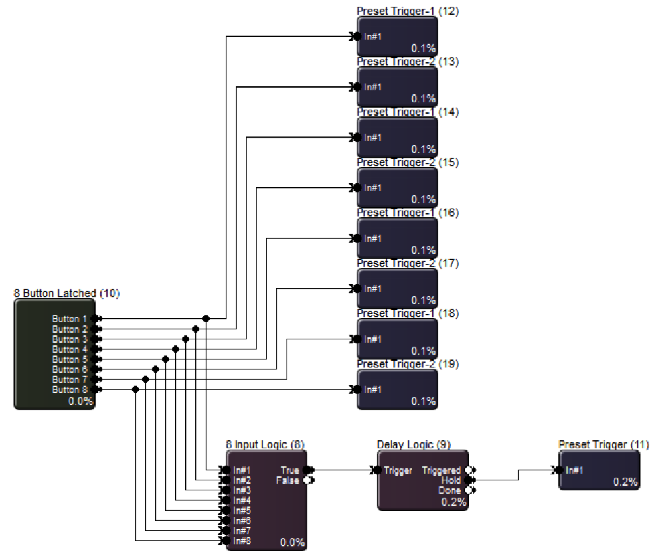
We’ve outlined a procedure that uses latching buttons in the place of momentary buttons as triggers – these latching buttons ultimately will act as if they are momentary buttons. This is accomplished by the use of a single Preset Trigger module which is triggered every time a latched button is pressed. It fires a “button off” preset to reset the state of the latching buttons to their off state. The preset is fired so quickly after the touch that the latched button appears to act as a momentary button.
For most applications, this workaround will do the trick nicely. The only drawback to creating a momentary button in this fashion is that you cannot hold it down. Therefore, this process is best used for controlling modules that are triggered via an impulse, such as preset triggers.
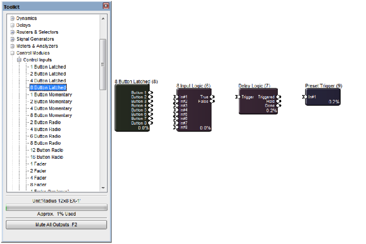
1. Drag the following modules into the design from the Toolkit (all are found
under the Control Modules heading):
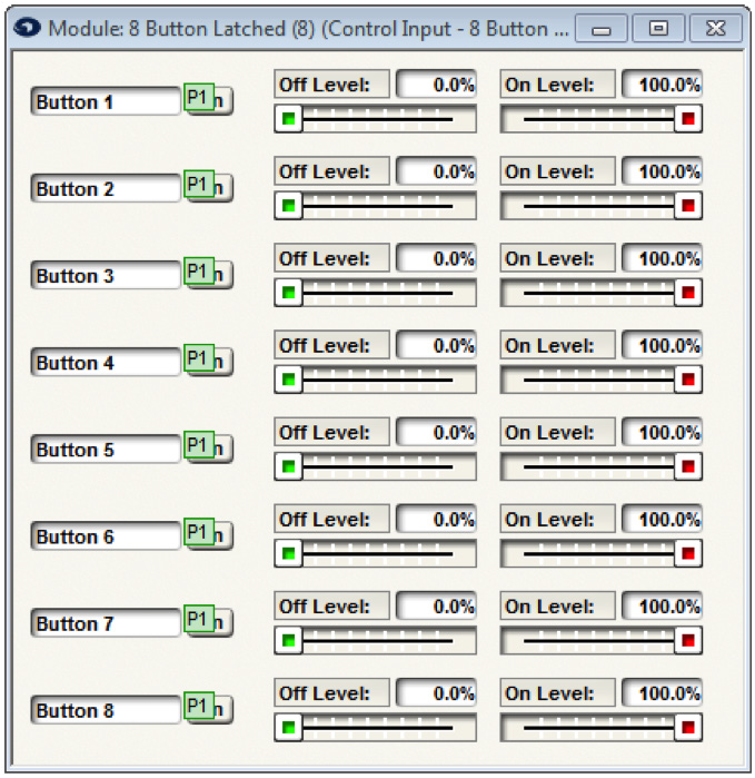
a. 8 button Latched
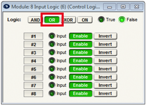
b. 8 Input Logic
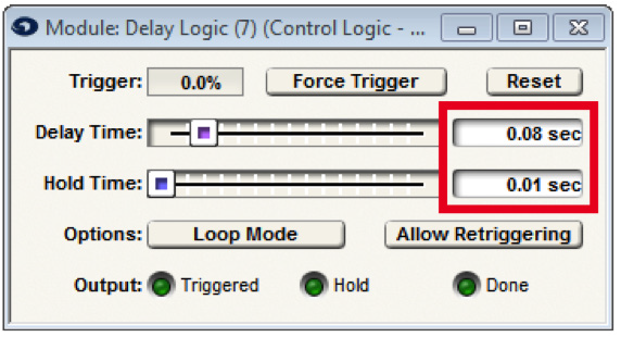
c. Delay Logic
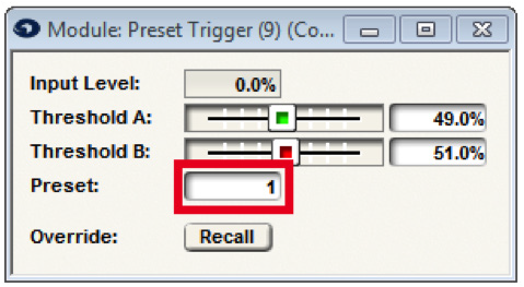
d. Preset Trigger
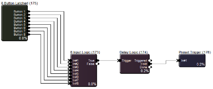
2. Wire them up as below:
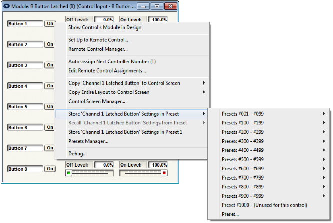
3. Next, take a snapshot of the latched buttons in their off states. Double-click the 8 button Latched module to bring up its GUI. Making sure the button is in its off state, right-click directly on the first button and store it to an un-used preset of your choice. Repeat for the rest of the buttons, making sure to use the same preset number for each.
4. All buttons should appear as below (with whichever preset number you chose). If the green indicators are not appearing over the buttons, go to the Tools menu in Composer and be sure “Super-impose Assigned Controller Numbers” is checked.
5. Open the 8 Input Logic module and set the logic operation to OR.
6. Next, double-click the Delay Logic Module. Set its delay time to .08 seconds and its hold time to .01 seconds.
7. In the Preset Trigger module, enter the preset number from step 3.
8. Wire in some modules to be controlled. In this example, Preset Triggers are used.
9. The 8 Button Latched module contains the buttons to be controlled from SymVue. Re-open this module in Composer and copy the “On” buttons over to a new or existing control screen. These buttons will now function without the need for a “swipe” motion to engage them.
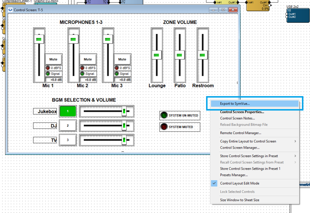
SymVue Control Screens are a powerful and flexible option for system control. This Tech Tip explains how to export a control screen to a T-5 touchscreen, Control Server, and Windows PC.
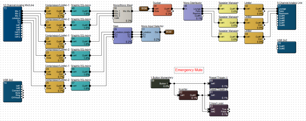
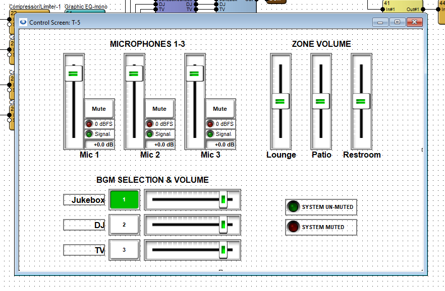
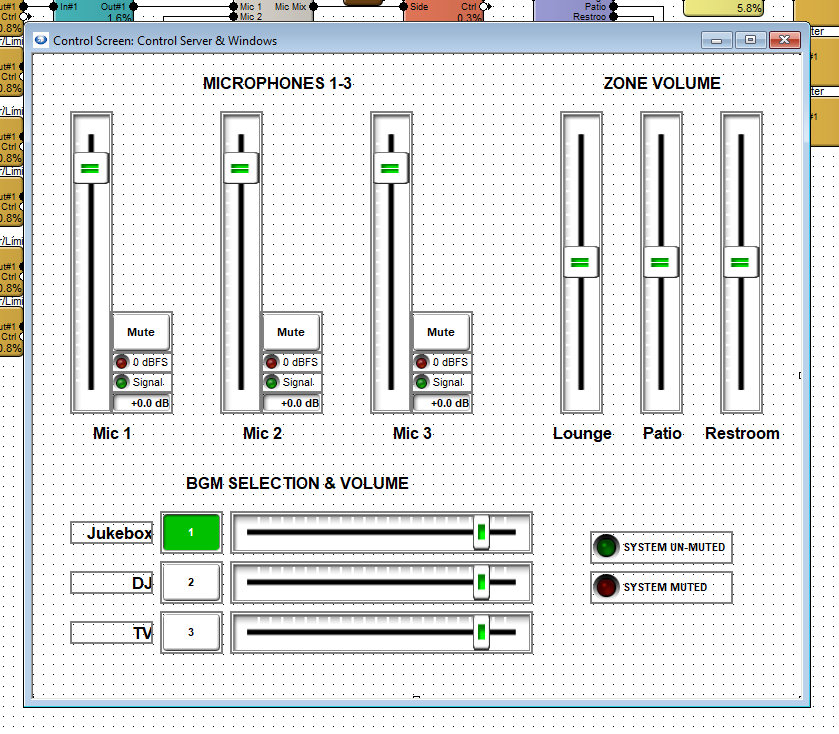
This example is for a three-zone venue with six inputs. User controls should include microphone level control, background music selection and level control, zone volume control, and an indicator if the emergency system mute is engaged.
In this example, we will only need to create two control screens; one for the T-5 touchscreen and one that can be used for both Control Server and Windows PC. Once both control screens have been populated with controls and designed according to the available space, open the touchscreen control screen.
T-Series Export:
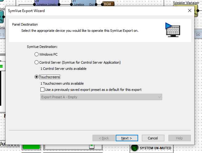
Right click in the background area and select Export to SymVue. Then select Touchscreens and click Next.
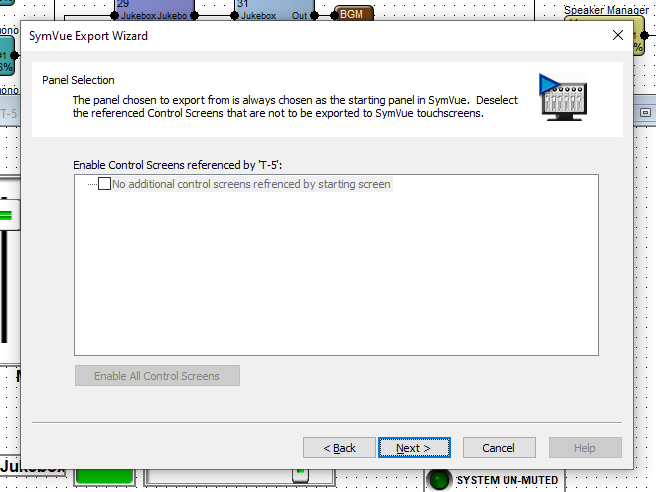
If there are more than one control screen intended for this configuration, this Panel Selection dialogue will allow you to select which screens should be included and referenced by this screen. When preferred selections are made (or if no other control screens are included), click Next.
Note: the “Home” control screen of a configuration is the one that is first exported through right-click > Export to SymVue.
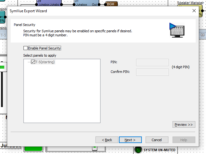
Panel Security allows you to set a PIN code for the desired control screens. This PIN will be used for all selected control screens. Control screens in a given configuration may not have varying PINs.
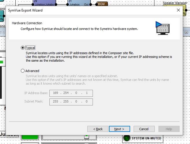
Hardware Connection allows for two options of locating the T-5 touchscreen. Select which is most appropriate for the installation – in the vast majority of cases, Typical is the appropriate selection.
Export Options is the last step. Export to Touchscreens should automatically be checked. The drop down provides options to export this configuration to a specific T-5 or a group of touchscreens.
Note: We strongly suggest selecting “Go Online with Composer site file” to avoid control subscription errors which can be caused by the touchscreen and Composer/DSP not sync’ing parameters.
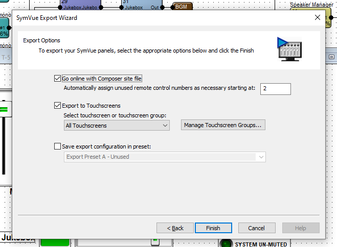
When ready, click Finish. This will export the configuration to the T-5 and push/update the archive on the DSP and go online.
Control Server / Windows PC Export:
Open the control screen for Control Server and Windows PC. Repeat the steps for T-5 touchscreen, making the appropriate selections for either.
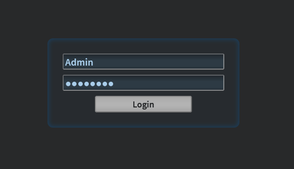
Once the configuration has been exported to Control Server, open up the Control Server’s WEB GUI and log into the Admin account.
Double-click on the Control Server or right-click > open in Site View.
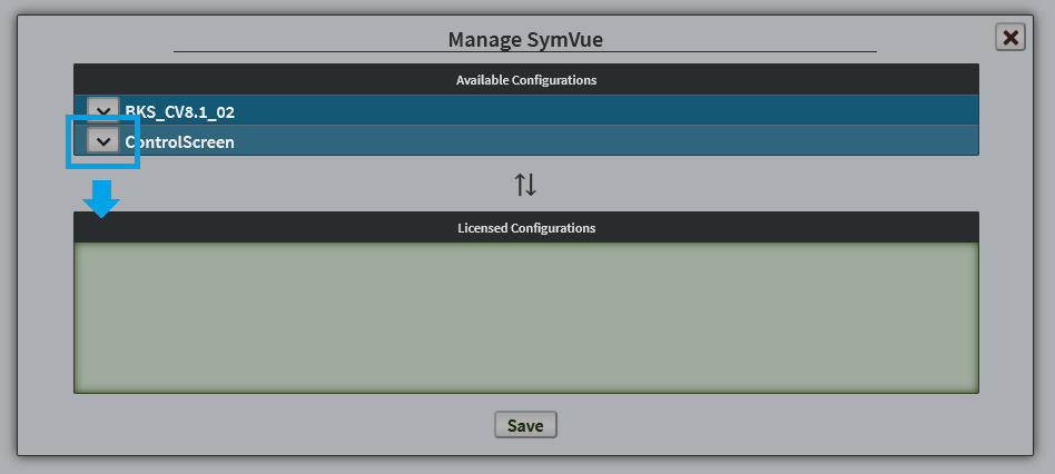
Once viewing the Status page, in the top right corner, go to Menu > Management > Applications and select SymVue from the App list. This will expand the available configurations list.
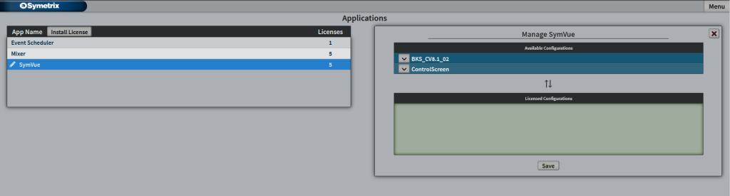
Click the down Arrow (or click and drag) on your control screen – this example “ControlScreen” – and click Save.
Then go to Menu > Management > Users. If you haven’t created a user account for the Control Server, you can do so here. Click on the user that will be accessing the exported configuration.
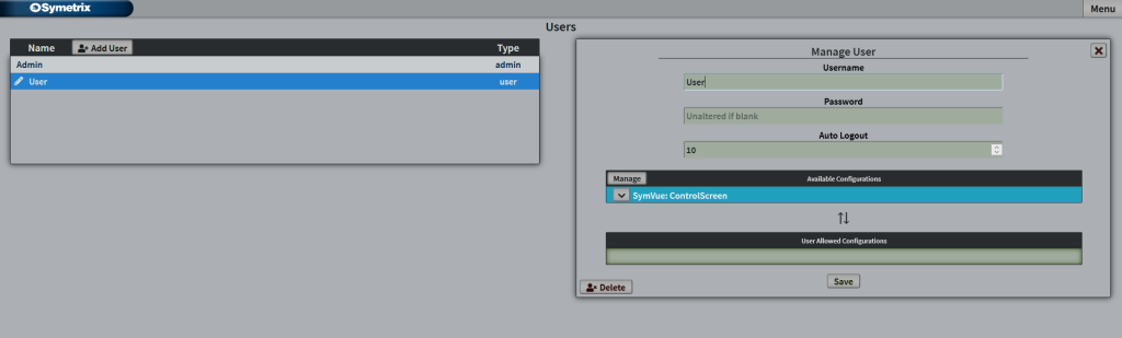
Click on the down arrow for the configuration that this user will access to place it into the User Allows Configurations and click Save.
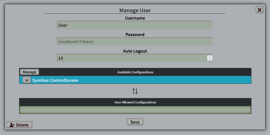
This user now has access to this control screen.
Additional note; Configurations, Licenses, and Applications:
A configuration is any number of single control screens grouped/exported together that act as one “set” of pages or screens. You can have any number of available configurations (sets of control screens) loaded into the Control Server. The number of licensesavailable determines how many of those configurations are allowed to be available to users. You can have any number of users with varying access to any number of the available licensed configurations. Every Control Server comes with 5 licenses, but more can be purchased if necessary.
These control screens are used through the SymVue Application, which is the same medium we use for our export to touchscreen or Windows PC. The Event Scheduler and Mixer apps you may see in Control Server or on export are not related to these control screen configurations.
In Symetrix DSPs, the word “active” isn’t quite the right term to describe presets. Presets are simply a snapshot of one or more parameters in a particular state, and are more so recalled than they are “active”.
However, when using a SymVue Control Screen, there is a way to offer what looks like an “active preset” indicator using the LEDs from an Input Logic module.
Let’s say, for example, that we want three volume presets that can be recalled depending on the time of day for an entertainment venue – low, medium, high – which could correspond to before, during, and after a performance.
In this example, we’ll use a 4 Channel Gain module that would control 4 zone volumes within the venue. Set the gain faders (and any other desired parameters) to the desired position for “Before” the performance.
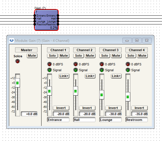
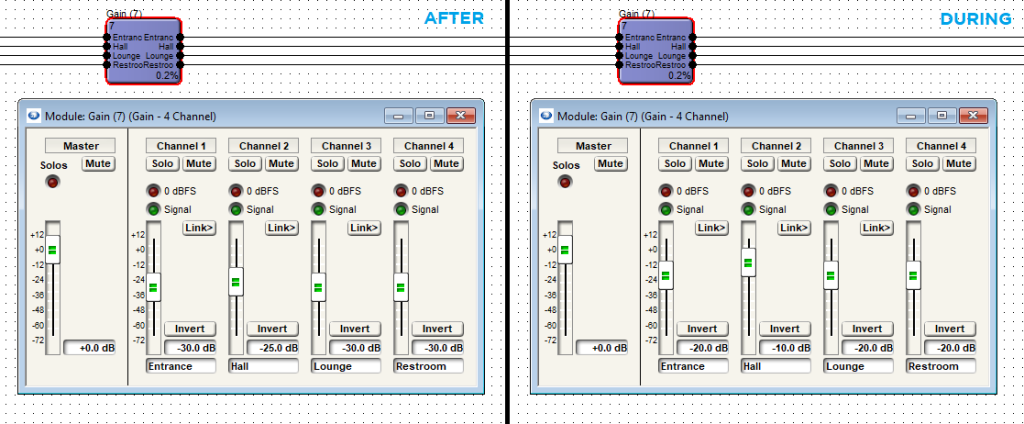
Next, set the gain faders to the other two desired levels for “After” and “During” performance.
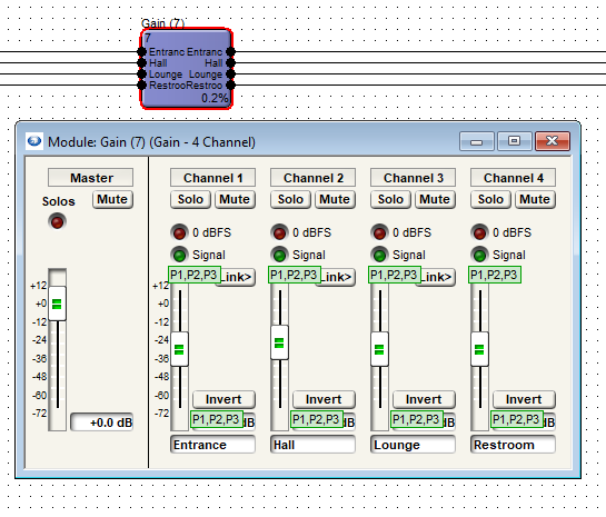
We can now see, with Super-impose Assigned Control Numbers engaged, that all faders have been assigned to Presets 1, 2, and 3.
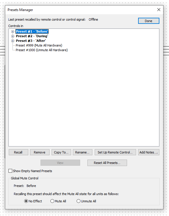
Now, we will rename these presets for easier identification later.
Tools > Presets Manager or Ctrl+G. Highlight the preset and click “Rename…” near the bottom.
Next, drag in a 4-Button Radio and a 4 Input Logic module, and wire them together. We only need the first three outputs to inputs as we only have three presets. We won’t be using the fourth output on the 4-Button Radio or the fourth input on the 4 Input Logic.
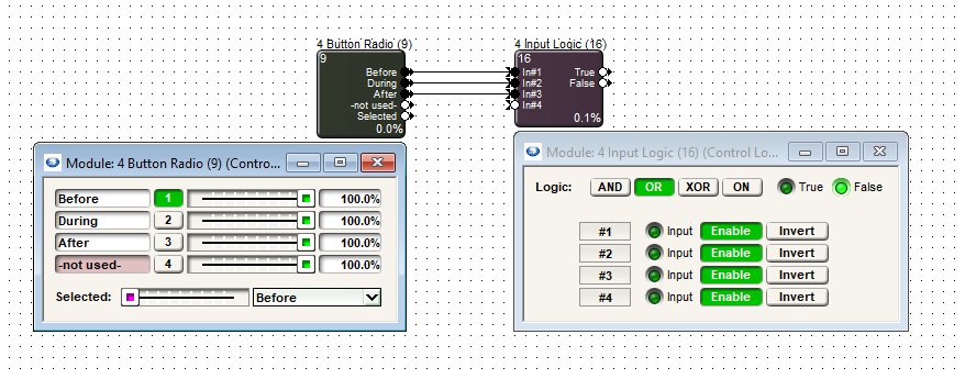
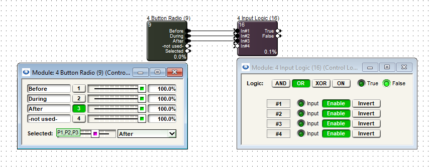
Set the 4 Input Logic module to the “OR” mode and then 4-Button Radio module slider to settings 1, 2, and 3, and add it to Presets 1-3 accordingly. The image below shows the module in the Preset 3 position.
Now, when a given preset has been triggered there will be a 100% control signal sent from the 4-Button Radio to the 4 Input Logic which will light up the LED for that given input.
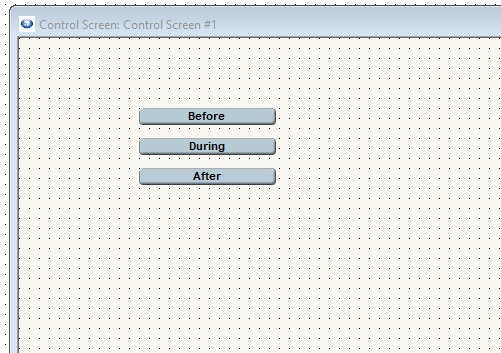
In your Control Screen, place Preset Recall buttons for all three of the created presets.
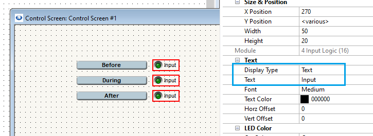
Next, copy each LED from Inputs 1, 2, and 3 in the 4 Input Logic module.
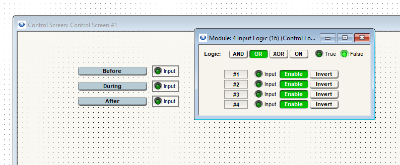
The “Input” text is still showing here. We can remove that in the parameter properties window and then resize the right margin to fit to the LED size. We can also resize the LED to the desired size.
Display type can be changed to “Symbol” or we can remove the text “Input”.
Now that we have the basic functional elements in place, we can Push and Go Online to test – Logic functions (these LEDs) don’t actively show while Offline in Composer.
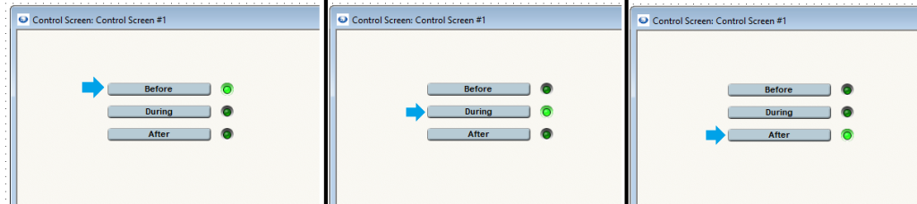
Additional note: While this method offers a way to indicate what looks like an “active” preset, it only shows the last recalled preset of these three that we have LEDs for. If a preset is recalled and any adjustments are made to any parameters included in these presets, the LEDs will not indicate this and will remain in the current state until the same or another Preset Recall button is pushed.
Unlike ARC Series remotes, W Series remotes do not have a built-in method for setting upper and lower boundaries for fader control. Fortunately, there is a way to do this in Composer using Control Screens.
1. Right click the desired fader and select “Copy to control screen”. Create a new control screen if necessary:
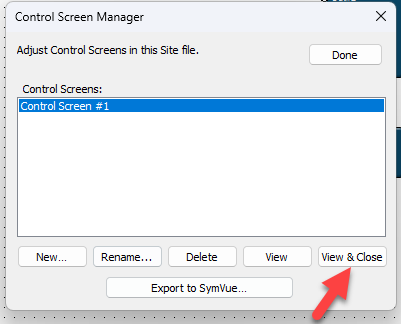
2. Go to Tools > Control Screen Manager:
3. Highlight the control screen created in the first step and select “View & Close”:
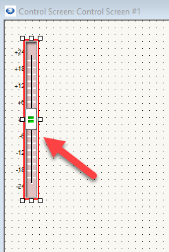
4. The fader in question will appear. Left click it to select it:
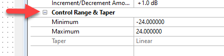
5. On the right side of the screen under “Properties”, locate “Control Range & Taper”:
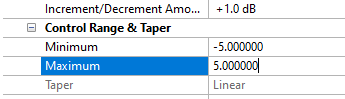
6. Under “Minimum” and “Maximum”, set the minimum and maximum values for the fader:
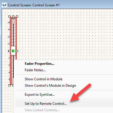
7. From here, right click the fader, select “Set Up to Remote Control”, and set it up to the W remote as normal:
Command Buttons in Composer can be used to launch 3rd party applications. The purpose of this Tech Tip is to illustrate how to set up the Control Screen Command Buttons to launch and control parameters in these applications. By making use of a script language named AutoIt and an associated script editor
named SciTE, functions such as mouse clicks, cursor movement and key strokes in 3rd party applications can be executed by Command Buttons. The 3rd party application could be virtually any Windows program. Windows Sound Recorder is being controlled by Composer in the following example:
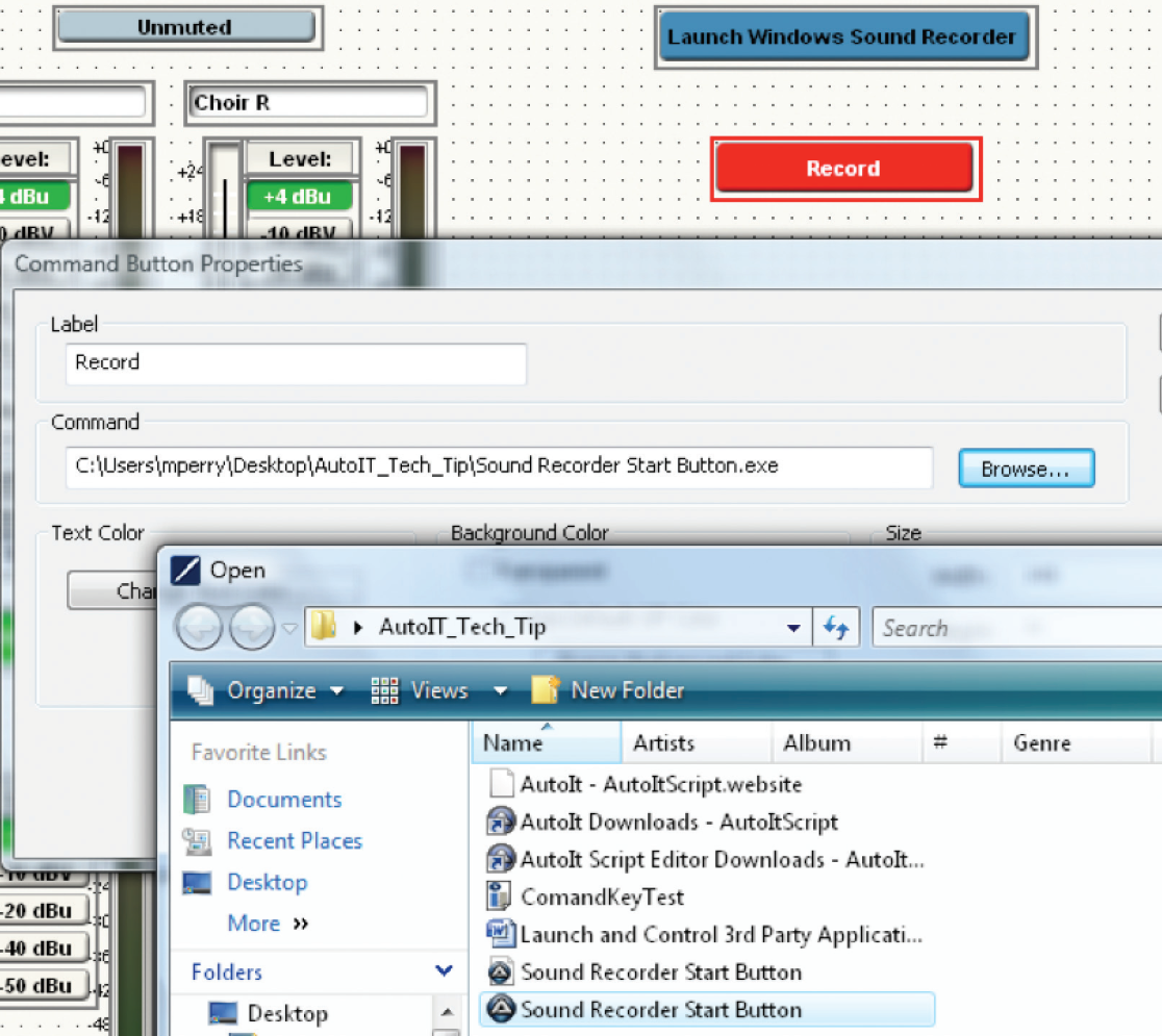
- First, set up a Control Screen in Composer.
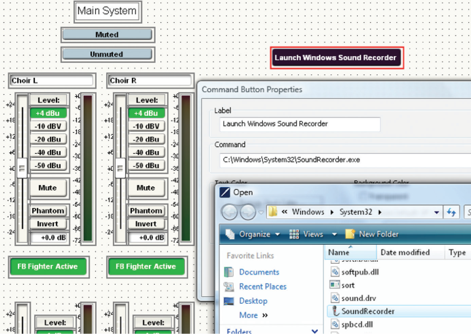
- Place a Command Button on the Control Screen. The “Command Button Properties” automatically opens after placement, in order to label the button. Choose “Browse” in order to direct the command button to the location where the desired program’s executable lives.
C:\Windows\System32\SoundRecorder.exe
By using the recommended script editor, SciTE, AutoIt is able to produce an .exe file which can execute a mouse click among many other functions. If one associates a Command Button with the executable file created in SciTE, the user can control the 3rd party application with the Command Buttons
- AutoIt and the recommended script Editor SciTE can be downloaded
from the following links:
http://www.autoitscript.com/site/autoit/downloads/
http://www.autoitscript.com/site/autoit-script-editor/downloads/ - Start SciTE from your Start Menu/All Programs/AutoItv3/SciTE Script Editor. Check the AutoIt Help File for the language’s syntax rules. Check the SciTE Help File for tips regarding the editor’s capabilities.
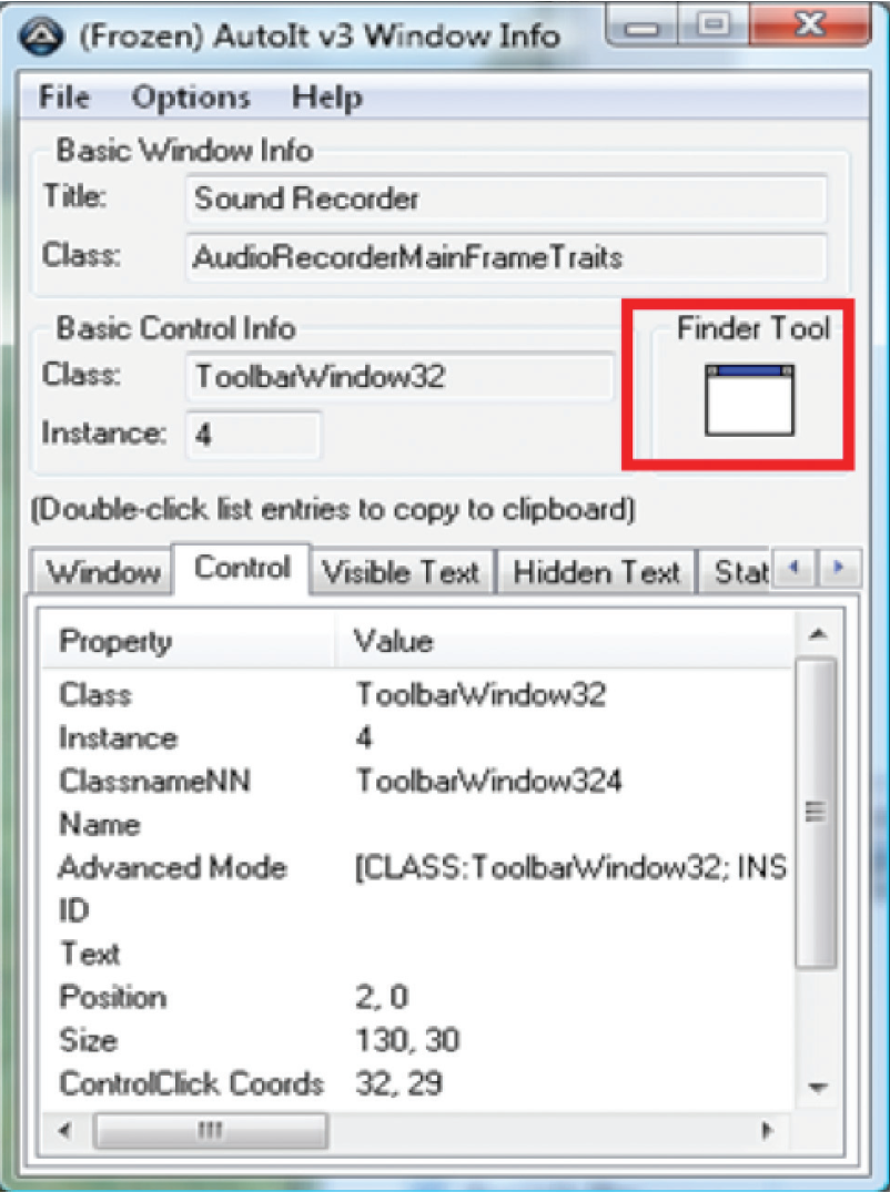
Open the program named AutoIt Window Info. Click and drag the order, or any button parameter in your chosen application. Make a note of the information on the line labeled “Advanced Mode,” which can be found on the Control tab.
- The first line of code entered into the SciTE editor in this example is an optional title line: Opt(“WinTitleMatchMode”, 2)
- The information required in order to activate the “Start Recording” Button can be gathered from the “Advanced Mode” line of the Control tab in the program AutoIt Windows Info, after the Finder Tool’s target has been dropped on the parameter to be controlled.
Below is the line of code to be entered into the script editor to activate the record button with a function:
ControlClick (“Sound Recorder”, “”, “[CLASS:ToolbarWindow32; INSTANCE:2]”)
ControlClick is an AutoIt script command to execute a mouse click.
http://www.autoitscript.com/autoit3/docs/functions/ControlClick.htm
- Convert the .au3 script document which you created in SciTE into an executable in the same directory by hitting F7 while the SciTE file is open. An .exe with an identical file name will be created in the existing directory, next to the .au3 file.
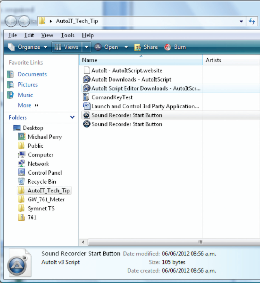
- Create another Command Button on your control screen in Composer which will be the “Start Recording” button execution.
- Right click on this new Command Button and choose “Command Button Properties”. Direct the browser for this button to the AutoIt executable file which you just created in SciTE.
- Once this is complete, save the Composer file. You may also export the control screen to SymVue at this time.
When the “Launch Windows Sound Recorder” button is clicked, it will initiate the Sound Recorder. When the “Record” button is activated, Windows Sound Recorder will begin recording.
Selecting the Control Server networking mode is an important step in the device configuration process. Each mode may be the ideal choice for a given circumstance.
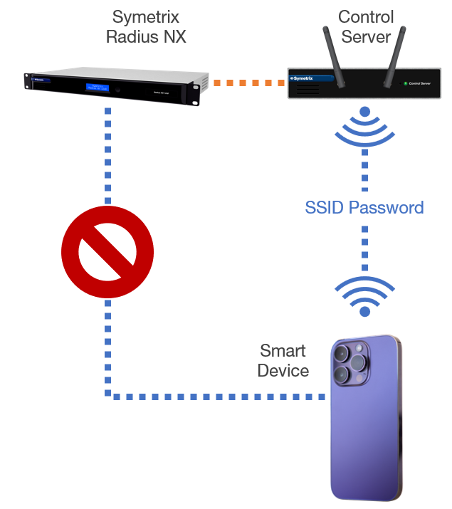
Control Server Networking Mode: Access Point (AP) Mode
In AP mode the Control Server is acting as its own WiFi Access Point “island.” With the Control Server and Radius connected over the network, configure the Control Server in AP Mode through its web interface. Any device with WiFi capability and a web browser can connect to the Control Server’s WiFi network through its SSID and password – just like any other WiFi network. An exported SymVue for Control Server control screen can be accessed from the smart device by visiting the Control Server’s IP address in a web browser. The Smart Device will not be able to connect directly to the DSP wirelessly.
Choose 1
AP Mode Notes:
- The Control Server and DSP can be connected directly or through a switch.
- The smart device must remain on the Control Server’s WiFi network to continue controlling the system.
- Control Server can allow control for any of our open-architecture DSPs.
Control Server Networking Mode: Client Mode
Choose 2
In this mode the Control Server is acting as an extension to an existing WiFi network. Meaning, the controlling device may connect to the existing network and still be able to control the system. With the Control Server and DSP connected over the network, configure the Control Server in Client Mode through the web interface.
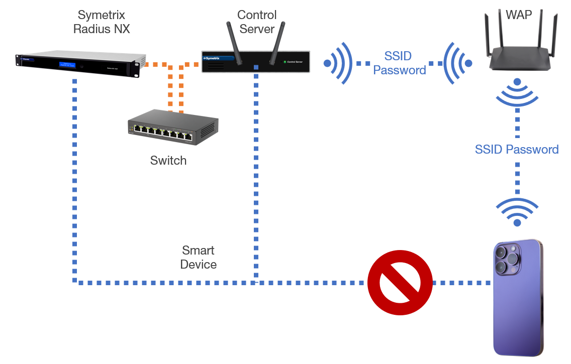
In the Control Server web interface, scan for networks and connect it to the existing WiFi network on site with the SSID and password. Then connect the smart device to the same existing WiFi network. Any device with WiFi capability and a web browser can access an exported SymVue for Control Server control screen by visiting the Control Server’s IP address in a web browser – the IP address given to the Control Server by the existing Router/WAP. The smart device will not be able to connect directly to the DSP wirelessly.
Client Mode Notes:
- The Control Server and DSP can be connected directly or through a switch.
- The Smart Device must remain on the existing WiFi network to continue controlling the system.
- Control Server can allow control for any of our open-architecture DSPs.
SymVue is a real-time user control panel application that displays control screens exported from Composer functioning as a multi-user, multipoint control environment for Composer systems.
SymVue runs on any Windows compatible device (XP, Vista, W7, W8, and any embedded version), including touch screen enabled PCs and tablets. The computer communicates directly with Composer hardware over Ethernet. The desired user control interface is created in Composer as a Control Screen and then exported to SymVue where it may be launched from one or many Windows devices for tailored, simultaneous operation.
When creating control screens within Composer to be exported to SymVue and opened on an end users Windows laptop, touch panel PC, tablet, or Surface Pro, it may be desired to create the control screen at a larger set of dimensions than the PC running SymNet Designer. Currently, Composer only supports control screen dimensions that will fit on the PC that the control screens are being designed on. There is however a method for creating a larger control screen dimension, locking the larger dimension which then creates scroll bars for navigation of the control screen being edited.
Here are the steps to creating a control screen with larger dimensions than the designing PC’s screen resolution:
1) Open a matrix mixer module and copy its connect matrix to a new control screen. If no matrix mixer is in the current design, add one temporarily for this step.
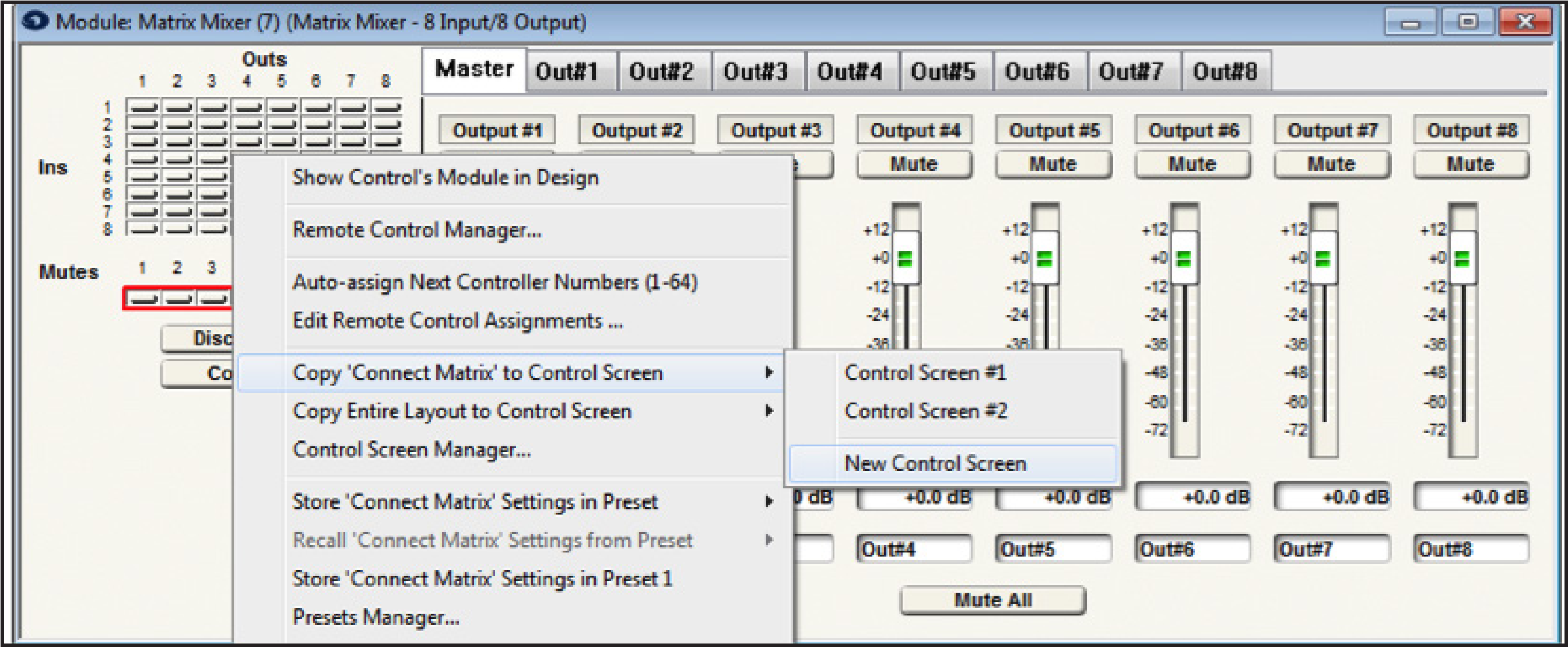
2) Position the connect matrix so that it is upper left hand justified as close to the control screen border as possible.
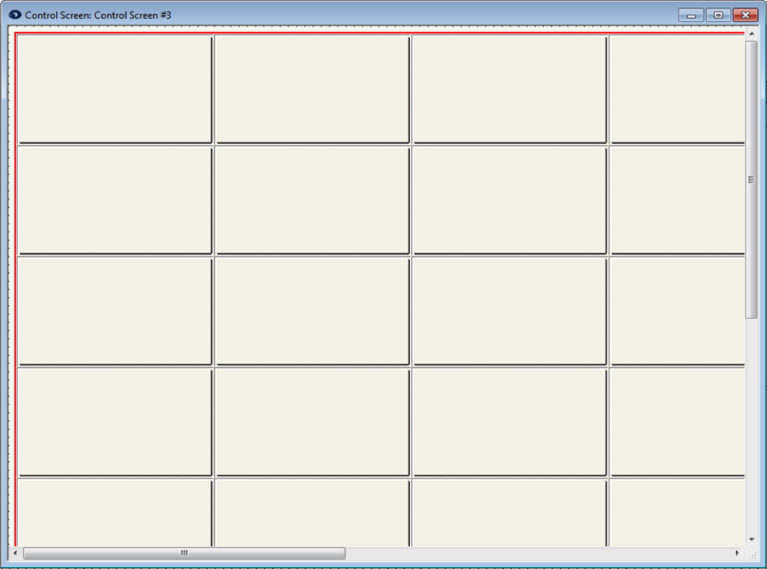
3) On the connect matrix on the control screen, double click to open its properties, or right click and choose “Properties – Matrix Button.”
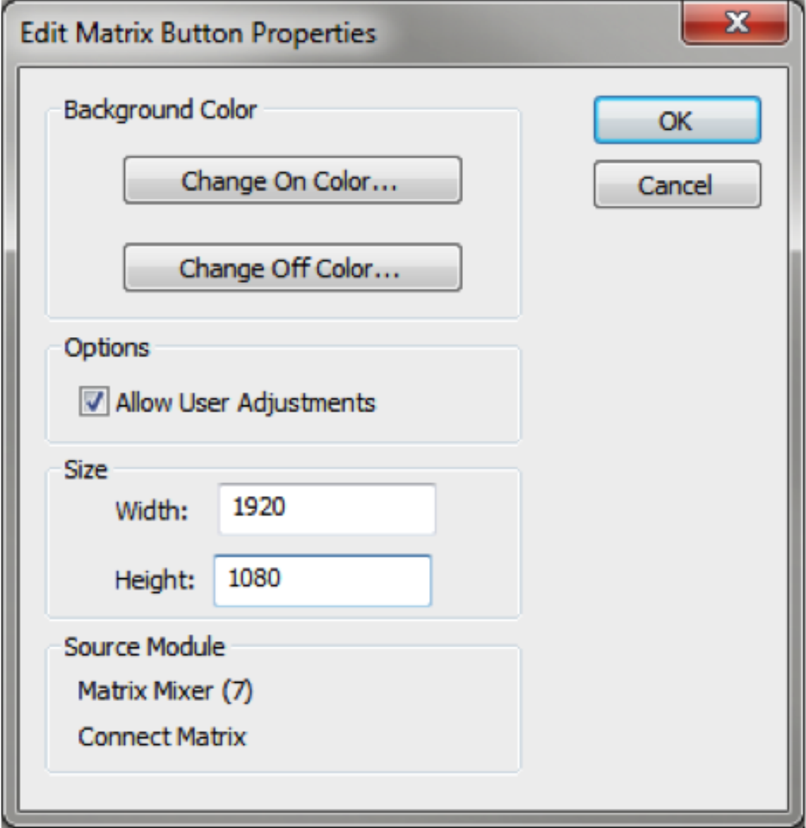
4) Set the width and height to the desired control screen dimensions.
5) Grab the bottom right corner of the control screen and adjust the control screen window slightly in size. This should instantly create scroll bars.
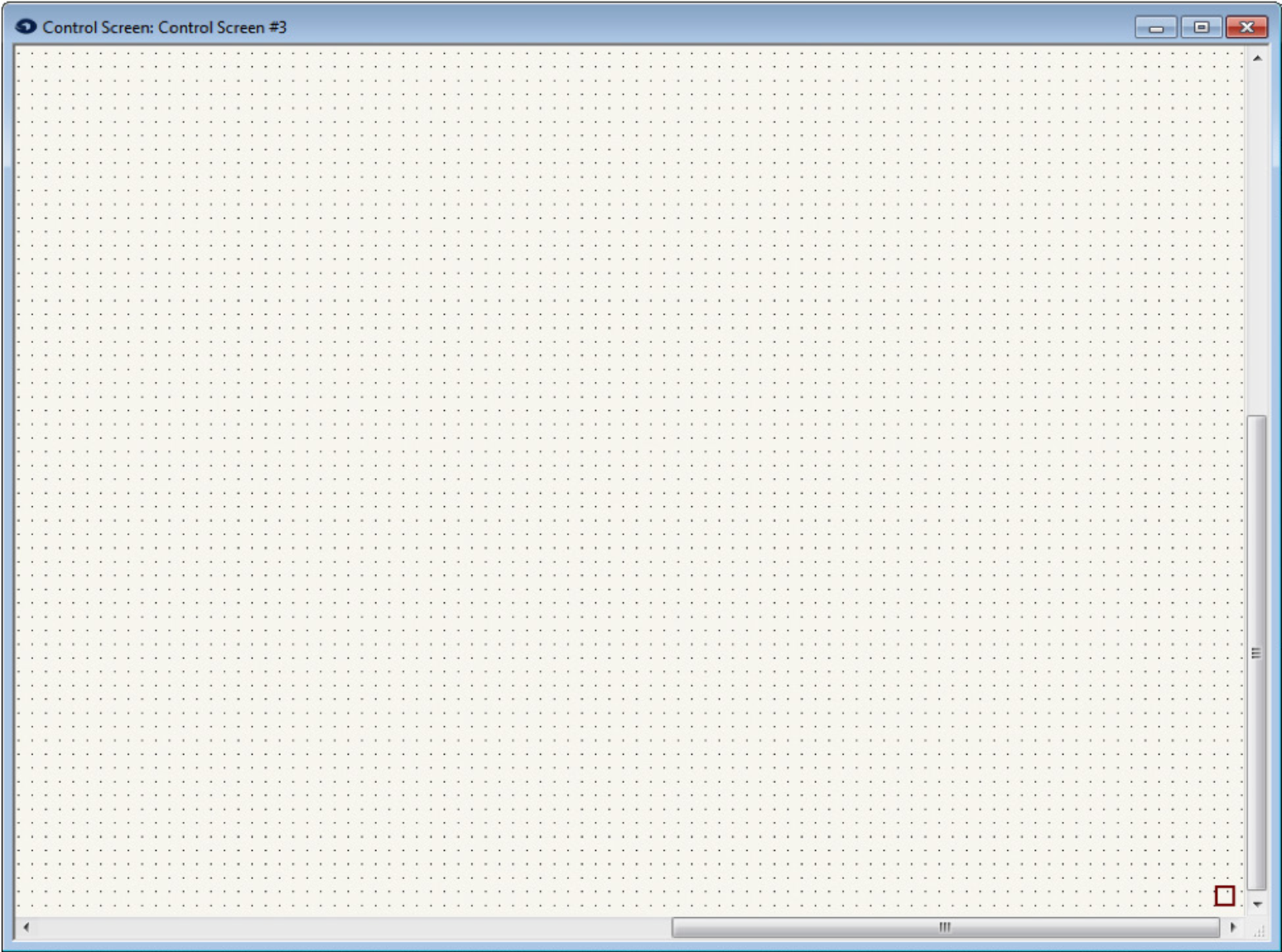
6) Using the scroll bars navigate to the bottom right corner of the control screen and drop an empty text field into the lower right corner. The example text box does have text in it for clarification, but in the design the text box should be empty.
.
7) Right click the text box to lock its position.
8) Delete the connect matrix from the control screen. If a matrix was added for this process, the module can be deleted from the design now.
9) The control screen dimensions are now locked and scroll bars will always be on the control page for as long as the empty text box is locked in the bottom right hand corner.
10) Populate the control screen with the desired controls and position them.
11) Once completed designing the control screen, “Export to SymVue” and then transfer the .svlx file to the Windows device that will run SymVue control system.
SymVue is our custom control screen software that comes packaged with Composer. Oftentimes, an installer will set up a Windows tablet to execute a SymVue file upon boot up, thus making things simple for the end-user and creating a fully immersive control screen environment. In this type of scenario however, it is best to give the end-user a means to shut down Windows properly, rather than doing a “hard” shutdown of their device at the end of the night.
This can be accomplished by the simple process of creating a .BAT file that resides on the device. This .BAT file can then be executed via a Command Button placed directly on the SymVue control screen.
Create the .BAT file:
- Open the Notepad application on a Windows PC.
- Type in the following command:
c:\windows\system32\shutdown -s -f -t 00
What the parameters mean:
-s: Tells the computer to shutdown
-f: Forces running applications to close.
-t: How long the device waits before shutdown is initiated (in this case, 0 seconds)
- Go the File menu and click Save As. From the “Save as Type” dropdown menu, choose “All Files”. For file name, type in “shutdown.bat”. Make sure to include the .bat file extension.
- Drop the .BAT file into a directory on the tablet or PC that will be running SymVue. Make note of this file path. For example “C:\Users\ndanielson\Desktop\shutdown.bat”.
Create the Command Button:
- In Composer, bring up the control screen to which you want to add a shutdown option. From the Toolkit, double-click or drag in a Command Button.
- The Command Button Properties windows will appear – In the Label field name it “Shutdown”. In the Command field type in the file path from step four above. Again, this needs to be the file path on the device that will be running SymVue.
Other button parameters such as color and size may also be edited in this screen.
- Position the Command Button on the control screen in the choice position. Of course, care must be taken on where to place the command Button, as you don’t want the end user to accidentally trigger the button and shut down their tablet until they actually mean to do it. Therefore, it may be best to create an isolated control page just for the shutdown button.
Use your best judgement.