


-
Type
- Dante
- Networking
- Control
-
System Management
- Composer Management Software
- SymVue Screen Authoring
- AV-Ops Center Remote Monitoring
- ARC-WEB Control Interface Signal Processing
- D100 AVoIP DSP Server
- Radius NX AVoIP DSP
- Prism AVoIP DSP
- Edge AVoIP DSP
- DSP I/O Expansion Cards
- Jupiter DSP
- Zone Mix 761 DSP I/O Connectivity
- xIO Bluetooth Endpoints
- xIO XLR Endpoints
- xIO AVoIP DSP Audio Expanders Control Systems
- T-Series Touchscreen Controllers
- W-Series Controllers
- Control Server
- xControl GPIO Expander
- ARC-Series Controllers
-
Type
- Dante
- Networking
- Control
-
System Management
- Composer Management Software
- SymVue Screen Authoring
- AV-Ops Center Remote Monitoring
- ARC-WEB Control Interface Signal Processing
- D100 AVoIP DSP Server
- Radius NX AVoIP DSP
- Prism AVoIP DSP
- Edge AVoIP DSP
- DSP I/O Expansion Cards
- Jupiter DSP
- Zone Mix 761 DSP I/O Connectivity
- xIO Bluetooth Endpoints
- xIO XLR Endpoints
- xIO AVoIP DSP Audio Expanders Control Systems
- T-Series Touchscreen Controllers
- W-Series Controllers
- Control Server
- xControl GPIO Expander
- ARC-Series Controllers
Jupiter DSP Tech Tips
This tech tip will explain how to properly integrate the External Control Inputs of Symetrix DSP units (Radius NX, Prism, Edge, xControl, Jupiter, Zone Mix 761). Both the physical hardware connections and programming setup will be covered.
Each External Control Input, also known as an Analog Control Input or GPIO, can be configured in one of two modes; as a dual switch closure or a potentiometer.
Dual Switch Closure mode is most commonly used with PTT/PTM (Push To Talk/Push To Mute) buttons on microphones, for an Emergency System/fire alarm relay connection that will mute or override the audio system, and for Room Combining that use switches on moveable wall partitions. The potentiometer mode is typically used to create an inexpensive, volume control for an input, source, zone, or output.
Zone Mix 761
Note: The Jupiter or the Zone Mix 761 supports a combination of up to 2 potentiometers or 4 switch closures.
Radius NX/Prism/Edge, xControl
Note: Edge, Prism, Radius NX, supports a combination of up to 4 potentiometers or 8 switch closures. xControl supports a combination of up to 8 potentiometers or 16 contact closures.
Using standard shielded twisted pair terminated with a terminal block on one end, External Control Inputs may be freely assigned to parameters in the Symetrix DSP hardware. The operational mode (switch closure vs. potentiometer) must first be configured while on-line or off-line using the Configure External Control Inputs dialog. While on-line with the DSP using the Symetrix software, a potentiometer can be calibrated for maximum travel or scaled as described later in this document.
Typical Control Switch Wiring
Note: +V(OUT)=A, INPUT=B
Typical Control Potentiometer Wiring
Configuring External Control Inputs in a Jupiter or Zone Mix 761:
Example 1: Switch Closure
This example will step through the setup of an Emergency System fire alarm mute in the Zone Mix 761 where the fire alarm relay connects to External Control Input 1A. The process is virtually identical for the Jupiter software/hardware.
First, make the physical connections using the above picture as a guide. Then, once the Zone Mix 761 software is online with the hardware, launch the External Controller Wizard. It should be noted that configuring the External Control Inputs on a Jupiter or Zone Mix 761 is straight forward since the External Controller Wizard simplifies the process.
Choose Add New External Controller, select Switch or Control Voltage and then click Next.
Now give the switch a descriptive name based on where in the venue it is located or based on what function it will provide. For example, the name could be as simple as “Switch” or as descriptive as “Fire Alarm relay”. Select the “Emergency” option for the Switch Function and click Next.
On the next page choose the desired function that will trigger based on the state of the input connection provided by the emergency fire alarm system. The two options are: Mute All Outputs or Route Input 3 to Specified Outputs at a Pre-Determined Volume Level. Select the appropriate function and click Next.
For an Emergency Fire Alarm Mute select the “Mute All Outputs” option and click Next.
On the next page, remember to select the correct physical External Control Input that the emergency system relay will connect to. This example uses Switch Closure 1A.
Once the correct input is selected, click Next.
Now, select the emergency route logic based upon how the Emergency relay functions. For reference, the software presents a few practical examples: Normally Open/Active Low and Normally Closed/Active High. Click Finish to close the External Controller Wizard or Next to return to the first page and setup another ARC remote.
Example 2: Potentiometer
This example will step through the setup of a potentiometer in the Zone Mix 761 where the RC-3 connects to the External Control Input 1. The process is virtually identical for the Jupiter software/hardware. Once connected, you can launch the External Controller Wizard and add it to your configuration.
Choose Add New External Controller, select Potentiometer (RC-3) and then click Next.
The RC-3 can control any of the twelve input volumes, the two program volumes per zone, the six zone volumes, the six output volumes, or sets of linked volumes. The particular gain stage the RC-3 will control is selected with the Parameter drop-down menu.
It may be a good idea to give the RC-3 a descriptive name based on where in the venue it is located or based on what function it will provide, especially if both External Control Inputs have a potentiometer or RC-3 connected. Click Next when done.
Select the appropriate External Control Input and click Next.
On the calibrate page, the range of the controller fader can be restricted or scaled by typing the value in Upper and Lower Limits. When finished, click Next.
In this step, calibrate the potentiometer to the 761’s External Control Input to ensure the full travel of the pot is utilized. The Zone Mix 761 software must be on-line for the calibration function to work. Rotate the pot fully counterclockwise (CCW) and click the Set Minimum Position button. Now, rotate the pot fully clockwise (CW) and click the Set Maximum Position button. Once completed, click Next and the software will return to the External Controller Wizard’s opening screen. Continue to add controllers or edit existing
ones if needed. If finished, click the Finish button to exit the External Controller Wizard.
Configuring External Control Inputs in Radius/Prism/Edge, or xControl:
Example 1: Switch Closure
This example will step through the setup of an Emergency System fire alarm
mute for a system using Composer software, where the fire alarm relay output connects to External Control Input 1A on an xControl. The process is identical for setup and assigning External Control Inputs on an Edge, Radius or Radius AEC.
After making the physical connections, while in Schematic Edit Mode, configure the External Control Inputs by right-clicking on the unit in Design View and select “Configure External Control Inputs…”:
Remember to select “Dual Switch Closure for the input the Fire Alarm relay connects to.
Now that the External Control Inputs are configured, here is one example of control logic programming for an emergency mute/unmute function in Composer 2.0 software.
Note: Alternative logic programming examples are located at the end of this section.
Double click the “1 Button Latched” module to open its user interface. Then assign the selected Analog Control Input to the “On’ button by right-clicking directly on the “On” button and selecting “Set Up Remote Control.”
Click the drop down arrow under Remote control device and select “Remote Analog Input – ‘xControl’” to assign an External Control Input from the xControl. For assigning an External Control Input from an Edge or Radius choose the “Local Analog Input –“Radius12x8-9” or whatever “Remote Analog Input” is appropriate.
Click the drop down arrow under Select Analog Control and choose the switch input that matches the physical wiring on the External Control Input. This example uses Switch 1A. Select OK when finished.
Once the External Control Input is assigned to a fader or button an A1 “Highlighted Assigned Control Indicator” appears super imposed on the “On” button.
Note 1: Alt+M or Tools->Super Impose Assigned Controllers must be checked.
Note 2: If the system mute performance is inverted set the Off Level to 100% and On Level to 0.0%.
Double click the “2 Input Logic” module and select “OR”. When the button is triggered, it will set the output signal to True or False when the button is On or Off, respectively.
Double click the “Preset Trigger 1” module and assign Preset #999. Composer 2.0 automatically creates Preset#999 to mute the hardware without affecting the individual output mute states. This will mute all hardware when the latched button is triggered by the fire alarm relay.
Double click the “Preset Trigger 2” module and assign Preset #1000. Composer 2.0 automatically creates Preset#1000 to unmute the hardware without affecting the individual output mutes states. This will unmute all hardware when the fire alarm relay is reset.
Note: In the Preset Manager for Composer 2.0 Preset #999 and #1000 are pre-configured for the emergency mute/unmute function, equivalent to the F2 button in Composer. 999 = Mute All Hardware. #1000 = Unmute All Hardware.
Alternative Methods:
In this example an “Inverter” module is used in place of the “2 Input Logic” module and will perform the same function as the “False” output of the 2 Input Logic (11) module from the previous example.
Here, a Super Module from Tools->Super-Module Library Manager is used for the Emergency System Mute.
Once completed, Push the file to the system.
Example 2: Potentiometer
This example will step through the setup of a potentiometer in the system using Composer 2.0 software, where the RC-3 connects to the External Control Input 1on an xControl. The process is identical for setup and assigning External Control Inputs on an Edge, Prism, or Radius.
Note: In potentiometer mode, A is the +V output and B is the voltage input.
After making the physical connection, configure the External Control Inputs by right-clicking on the unit in Design View and select “Configure External Control Inputs…”:
To configure the input for use with a potentiometer, select the appropriate input tab, and then select the “Pot – Connect a variable voltage input (0-5V)” radio button. Select “OK” when finished.
Pot Calibration:
Note: SymNet Composer must be connected to the DSP hardware with the input configured as a “Pot” in order to calibrate the input. The potentiometer must be physically wired to the External Control Input as well.
Calibrating the External Control Input determines the way the 0-5V potentiometer affects Composer parameters. There are two separate areas that can be altered:
- Compensation for pots that don’t get all the way down to 0V or all the way up to 5V. This could happen because of characteristics of the pot itself, or resistance in the connection between the pot and the unit, especially with long wire runs. This is referred to as Calibrating Pot
Range below. - Limiting the range of parameters controlled by an analog input. This is referred to as Calibrating Control Range or scaling the range.
This setting should match the control input of the pot being calibrated. If a pot is connected and the settings are correct, turning the pot should move the small indicator along the Current input position line. The value of the pot (0-255) is also updated to show the current level generated by the pot. Zero represents GND or 0V, 255 represents 5V, and the range is linear.
Calibrating Pot Range:
To compensate for a pot that does not cause its assigned fader in software to travel the entire range when the physical pot is turned to is lowest and highest position, make sure the pot is connected to the one of the 8 External Control Inputs and the correct input tab is selected in the Config External Control Inputs Window of Composer 2.0. Turn the pot to its minimum value (usually all the way counterclockwise). Click the “Set Minimum Position” button. Next, turn the pot to its maximum value (usually all the way clockwise). Click the “Set Maximum Position” button.
Note: These settings can be used to compensate for a reverse-wired pot. To reset the calibration, click the Reset Min/Max Positions and they will be returned to their defaults.
Calibrating Control Range:
It may be desirable to limit the end user range of a potentiometer connected to an External Control Input and its effect on a gain stage. For example, if a pot is controlling a volume fader, it may be preferred to limit the fader range the end user can access from -30dB to 0dB rather than the full -72dB to +12dB range allowed in the software.
To limit the upper range of a control, enter a value less than 100% for the maximum level. To limit the lower range of a control, enter a value greater than 0% for the minimum level. When set to 100% and 0%, the control is allowed to travel the entire range shown in the Composer GUI. Other values reduce this range accordingly. Some experimentation may be required to find the percentage values that limit a range appropriate the current application. As an example, for a fader with ranges -72db to +12db, 84% is equal to 0dB.
Important Notes:
By setting the minimum value to a number larger than the maximum value, it is possible to reverse the operation of the pot or compensate for a reverse-wired pot. To reset the calibration, enter 100% for the maximum level and 0% for the minimum level.
If it is desired to reset all analog calibration data for a unit, use the Erase Memory command found under Hardware->Upgrade Firmware. Select only Analog Calibration Settings and hit ERASE.
All settings made using this dialog box are stored in the hardware, not in the site file. Changes made take effect immediately without the need to download the entire site.
Assigning a Parameter:
Right-click directly on the parameter and select “Set Up Remote Control.”
Click the drop down arrow under Remote control device and select “Remote Analog Input – ‘xControl’” to assign an External Control Input from the xControl. For assigning an External Control Input from an Edge or Radius choose the “Local Analog Input –“Radius12x8-9” or whatever “Remote Analog Input” is
appropriate.
Click the drop down arrow under Select Analog Control and choose the pot that matches the physical wiring on the External Control Input. Select OK when finished.
Once the External Control Input is assigned to a fader a P1 “Highlighted Assigned Control Indicator” appears super imposed on the GUI. Note: Alt+M or Tools->Super Impose Assigned Controllers must be checked.
Once completed, Push the file to the system.
Inspired by the ‘apps’ paradigm of smart phones, Jupiter is a turn-key audio DSP solution utilizing pre-designed apps – each optimized for a specific venue or application. A powerful component of Jupiter is the ability to create Custom Presets. This Tech Tip will take you through this process step-by-step using a
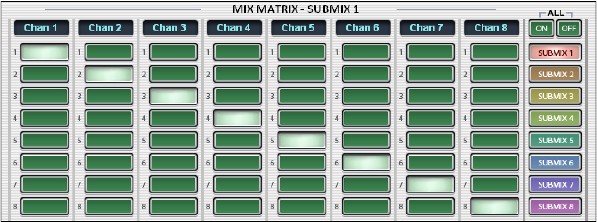
Mix Matrix for an example.
The Custom Preset allows Jupiter users to narrow and capture any parameter or combination of parameters to a recallable preset. (A Global Preset is also available. This captures the current state of the entire app.) Custom Presets are commonly used in mix matrices so that routing changes (source select,
output assignments, etc.) can be made without affecting other real-time controlled parameters like volume.
Step-by-Step
1 Set up the Mix Matrix in the exact configuration that needs to be recalled by the preset.
2. Go to the Tools menu and choose Store Preset.
3. Name the preset and select a location (50 available). Select Custom Preset and click Choose Parameters.
4. Use the browser categories to narrow the parameters to only those you wish to capture in the app, in this example the Matrix. Take careful note of which Matrix buttons to select as you may need to include ones that aren’t currently connected to ensure that the intended channels are ‘on’ or ‘off’.
5. Click ‘OK’ to confirm your parameter selections. Then click ‘OK’ again to confirm preset name and location.
This process is the same for any other configurations (mute, volume, EQ, etc.) in the app that you wish to isolate and capture for later recall. These stored presets are also available for triggering from your Symetrix ARC wall panels or 3rd party controllers.
Summary
Jupiter’s Custom Preset feature allows you to store the current state of any combination of parameters into a recallable preset for flexibility in real-time configuration changes. For more information contact support@symetrix.co
There are two types of presets available in both Symetrix integrator series DSP’s, Jupiter and Zone Mix 761. These preset types include global and custom presets. When setting up presets for recall it is important to understand the differences between the two options to best serve the intended purpose.
Global presets mean just that; global. Every parameter in the program file will be saved. This means no matter what changes might have been made after the program was last updated to tune the speakers, set input gain, etc. a global preset may return multiple parameters back to a prior state. Global presets are most useful in situations where a “system default” state is necessary. For example, this can be used by an end-user for easy troubleshooting, returning the system back to what should be a known good state.
Custom presets on the other hand allow us to select only the specific parameters we want to include in the preset. Custom presets are useful in situations like a restaurant or multi-purpose venue where certain times of day require different routing or base audio levels, or even to mute certain outputs.
This example will show the process of setting up two different custom presets for a location that is a coffee shop in the morning and a small performance venue at night. And quickly, will cover adding these presets to the Event Scheduler so that they will automatically trigger at a given time of day. The intended purpose is that the volume levels will be lower and certain output channels will not be active in the morning. Meanwhile, in the evening, some volumes will be higher and those speakers not used in the morning will be active.
We will also first set up a global preset that will be the known working state that can be recalled at any time. This example will not cover setting up remote control for preset recall. Refer to the Help File under Help, Contents, and searching for presets for more information.
First, let’s review the current state of a few parameters, remembering that global means everything. Input levels are set as they are, given the source devices and material. Output levels are set as they are as well, given the sources and material.
The matrix and sub-mix matrix are both set accordingly that music and TV are not routed to the front of house speakers via sub-mix two, but all mic and line inputs are routed to all outputs via sub-mix one.
Let’s begin setting up the default state preset by going to tools, store preset. Global preset is selected by default and we can change the name to default and ensure the location is set to location one. Click OK to save the preset. Now to set the two custom presets for morning and evening, we need to place the parameters we want to affect into the state that we want them. We’ll then store a new custom preset, only selecting those parameters to include.
Opening the sub-mix matrix we can see columns for the sub-mixes that then rout to the analog outputs. For organization and clarity, we can rename these two sub-mixes to mic line and BGM. The morning preset should make it so that the overall volume is lower. We can either use the sub-mix faders or the output master faders, but in this scenario we’ll use the master faders. Lower the fader from 0 dB down to -20 dB. Then lower the output two master to -20 dB, and then three and four. Even though the BGM inputs won’t be routed to outputs five and six, we can still lower the master faders to -20 dB as well, for good measure.
Now we need to activate some mute buttons for the front of house channels, outputs five and six, because these speakers don’t need to be active in the morning. We could simply mute these output channels at the analog output, however these mutes are post-limiter. This can potentially put the downstream sound system at risk of being overloaded with too much signal if the mute is suddenly disengaged. Engage the master mute button on channels five and six in the sub-mix matrix. Now that we have all desired parameters in the state the we want them, let’s review and begin building presets.
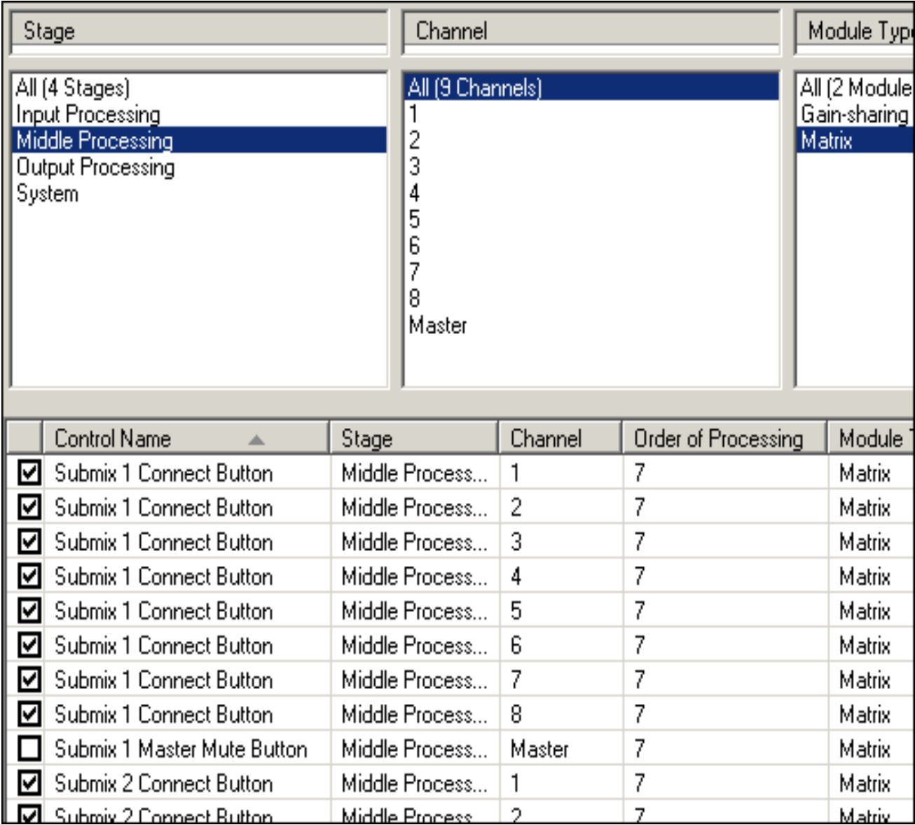
Go to tools, store preset. Edit the name to morning and select custom preset. Then select choose parameters. We need to include the sub-mix master gain faders for channels one through six as well as the mute buttons for channels five and six of the sub-mix matrix.
We can narrow down our available results by the filters at the top. The sub-mix matrix is middle processing. We are only considering channels one through six, but all channels won’t get in our way. Select sub-mix matrix from the module type.
Now we’ve filtered out hundreds of parameters, but still have quite a number of them left. Initially, let’s grab the master faders. Select fader from the control type. The control name we’re looking for is sub-mix one master gain fader. Check the box for this control and then for sub-mix two gain fader, and three. And then four, five, and six.
Now that we have the faders included in the preset we can add the two master mute buttons. From the filter area, click button. Similar to the fader, the control name we want is sub-mix master mute button. For this preset we only need to mute channels five and six. Check the boxes to include them in the preset.
To double-check our work, we can click All in the control type filter and then select “included in preset”. There should be eight parameters; six master faders and two master mute buttons. When all required faders and mute buttons are included, click OK to save this parameter selection. Then click ok again to save this preset.
Now, to save the evening preset we need to move the master faders and mute buttons into the desired position.
Move the faders of channels one through six to -10 dB and disengage the master mute buttons for channels five and six. Now go again to tools, store preset. Name this preset evening, select custom preset, and click choose parameters. Filter the results as we did before. Middle processing, sub-mix matrix, button and fader accordingly.
When all required controls are included, click ok, and then ok again to save the preset. Now that we have all three presets saved we can test them to make sure we’ve included the correct parameters and that they move to correct position.
Looking at the sub-mix matrix, go to tools, recall preset. Then select preset one for the default state and click ok. All sub-mix master faders should be now set to 0 dB and mute buttons disengaged. Once all presets have been confirmed we can set up the event scheduler for the morning and evening presets.
Go to tools, event scheduler. Here we can select a particular day and click add event. Name the event morning, select preset two for morning, then set the time this preset should be triggered. This example will leave the time at 8 am.
Now select recurring event. Choose daily and select all days of the week except Sunday. Then click ok. Now the morning preset will trigger every morning Monday through Saturday at 8 am. Click add event again. Name the event evening and select the evening preset. Change the time to 5 pm. Then choose recurring event and daily. This time only choose Thursday, Friday, and Saturday. Click ok to save this event trigger.
Now click ok in the event scheduler to save these triggers.
That’s it! You can now create your own custom preset as well as set them up to automatically trigger.
Applies to Radius NX, Edge, Prism xControl, Jupiter, and Zone Mix 761
This tech tip will explain how to properly integrate the Logic Outputs of the above DSP units into your installation. Typically these outputs would be utilized in a couple of ways – driving LEDs in order to give visual feedback to an end user, or controlling an external relay for switching other equipment, such as a projector screen or rack of other equipment. In order to do this is as seamlessly as possible, it is first necessary to know some basic facts.
First, each of these logic outputs is the open collector of a switching transistor that has its emitter tied to ground. What does this mean to you? These are not dry contacts that are simply open or closed. When the transistor is inactive, 5V is present at the logic output. When the transistor is activated, the 5V is shunted to ground through the transistor’s emitter, which results in 0V at the logic output.
Here are the specs for the logic outputs that we’ll be referring to in this tech tip:
- The logic output is pulled high (5V) when inactive.
- The logic output goes low (0V) when active.
- The maximum logic output source current is 10mA.
- The maximum external power supply voltage is 24 VDC.
- The maximum external power supply current sinking is 50mA.
How to Drive an LED
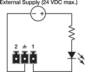
With a max output current of 10mA, it is possible to drive an LED directly from the logic output without needing a current-limiting resistor (there is an internal 500 ohm resistor). This of course depends on the forward voltage and forward current of the LED you choose (check the datasheet for your LED). In this case, simply connect as below:
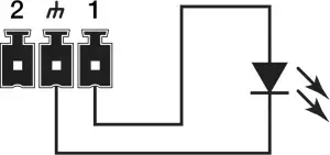
If you have an LED that requires a higher voltage/current demand, an external power supply will be needed. As stated above, the max external power supply voltage is 24 VDC with 50 mA sinking current. Hook it up as below:
You can calculate the resistor’s value by using Ohm’s law:
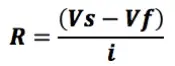
Vs = Supply Voltage
Vf = LED forward voltage drop
I = LED forward current (in Amps)
Round up your value to the nearest standard resistor value.
Note: Various styles of LEDs (from standard through-hole to panel-mounted) in a seemingly endless variety of values are readily available. The best approach would be to identify your needs in terms of LED type, then use the extensive search functions of sites like Digikey.com or Mouser.com to see what is available.
Driving Relays
There are two types of relays we’ll work with to control external devices, the most common being a non latching mechanical relay. Taking into consideration the 10 mA output current of the logic outputs, this type of relay will typically need to have its coil driven by an external power supply. As noted earlier, the external supply should not exceed 24 VDC, while the relay coil current should not exceed 50 mA. A relay such as the Omron G5LE-1A4 DC12 should do nicely.
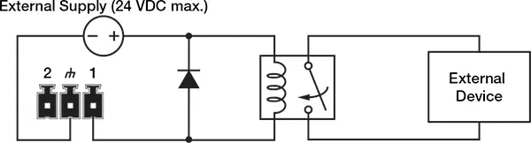
Take note of the flyback diode placed in parallel across the relay coil. This provides a path for discharge current to flow when the coil is switched off. Without this diode, there is the risk of damaging or destroying the internal transistor of the Symetrix device. Think of a flyback diode as the cheapest equipment insurance policy you’ll find anywhere. Use a 1N4004 or equivalent.
Another relay option would be to use a Solid State Relay (SSR), which typically has a lower current requirement for activation. Most installers use mechanical relays, but some of the advantages of SSRs are worth noting:
- Low turn-on requirements. There is no inductive coil to drive in an SSR. Instead there is an internal LED that toggles the relay, which typically requires very little current to turn on. If you choose one that requires less than 10 mA to activate, there is no need for the external power supply that you might need to power a mechanical relay coil.
- No mechanical wear-and-tear, arcing, or contact bouncing.
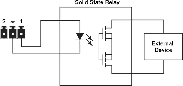
For a general use SSR, try a Panasonic AQV252G (max load voltage 60 VDC/VAC, max current of 2.5 A).
Triggering the Logic Outputs in SymNet Composer (Radius, Edge and xControl)
As a basic example, we’ll set up a logic output to be toggled on and off by an external device such as a Crestron or AMX controller.
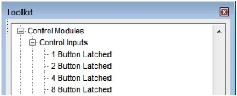
1 In Composer’s Design View, drag in a single Latched Button from the Toolkit.
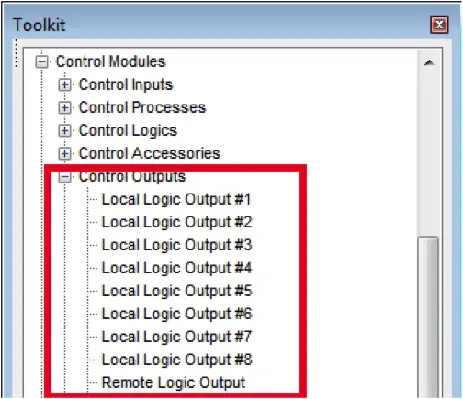
2. Drag in a “Local Logic Output #1” Module from the Toolkit. To use an xControl’s logic outputs, select the “Remote Logic Output” module instead.
3. Wire the output of the latched button module to the input of the logic output module.
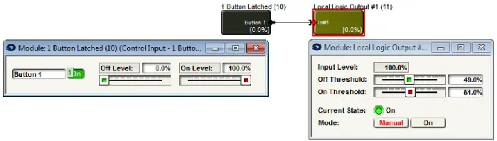
4. Right-click the “On” Button in the latched button module and click “Set Up to Remote Control.”
5. Select “Generic Controller Number Assignment” from the drop-down menu. Either keep the “Auto-assign controller number” checkbox selected, or un-check to type in your own controller number. Click OK, then push the site file to hardware.
6. You will now be able to control the button with your external controller.
- To enable the button, send this command to the DSP: CS <CONTROLLER NUMBER> 65535 <CR>
- To disable the button: CS <CONTROLLER NUMBER> 0 <CR>
Be sure to download the Composer Control Protocol from our website for full command details.
Triggering Logic Outputs for Jupiter and Zone Mix 761
Use the “External Controller Wizard” in the software to walk through programming your logic outputs.
- Setting up analog volume knobs and switches.
- LED clipping indicators for visual feedback.
- Triggering a power sequencer at 6AM every day.
These are just a few of the many things that can be accomplished with Symetrix hardware. All of our DSP units provide some degree of General-Purpose Input/Output (GPIO) via the External Control Inputs and Logic Outputs.
This document provides a side-by-side comparison of the GPIO counts for each piece of current Symetrix hardware, so you can spec the right gear for the job. Keep in mind that each individual External Control Input can either be configured to use a 10K potentiometer as its input, or two switches.
| Hardware | External Control Inputs | Logic Outputs |
| D100 | 0 | 0 |
| Edge | 8 switches / 4 pots | 8 |
| Radius NX 12×8 | 8 switches / 4 pots | 8 |
| Radius NX 4×4 | 4 switches / 2 pots | 4 |
| Prism | ||
| xControl | 16 switches / 8 pots | 16 |
| Jupiter | 4 switches / 2 pots | 4 |
| Zone Mix 761 | 4 switches / 2 pots | 4 |
For full details and walkthroughs on integrating GPIO, see the below Tech Tips:
Introduction
The purpose of this document is to provide a technical understanding of the Symetrix Control Protocol for Jupiter DSPs. It will define and illustrate the protocol used to communicate with the Jupiter products via a third-party interface.
Jupiter devices can be controlled by third-party controllers such as certain AMX or Crestron models, or any Ethernet equipped device that can be adapted to this protocol. The protocol consists of humanly readable text commands and responses. It is based on the Symetrix Control Protocol (described in a separate document) and inherits many of the features from that system.
Control is achieved by using a scheme of pre-assigned controller numbers. Nearly anything that can be adjusted from the Jupiter software can be controlled externally by referencing the appropriate controller number. The controller numbers for each Jupiter App may be browsed in the Custom Preset Parameter Browser. Refer to the Jupiter software help file for more information.
Conventions Used in this Document
- A dollar sign ($) preceding a set of alphanumeric characters denotes a hex value. All other number values should be considered decimal values. Example: “$A0” represents the decimal value of “160.”
- Values enclosed in [square brackets] are optional parameters and do not need to be include. If omitted, default values will be used as described for each command.
- The term “control application” is used to refer to the Windows-based graphical user interface software provided by Symetrix to configure Jupiter devices.
General Notes
Connections
All Jupiter products are equipped with Ethernet ports. The same port is used for host control (Jupiter software) and third-party control (with this control protocol).
Ethernet Port Configuration
Generally, no special configuration is required for the Ethernet port. The single Ethernet port on the device may be used for both the control application and for external control. Take note of the device’s IP address (listed in the Connection Wizard), as you will need to send all commands to this address. The commands Set Quiet Mode and Set Echo affect the Ethernet port. The device’s default settings (Quiet Mode ON, Echo OFF) are typical for most applications, so most users will not need to know about these commands. However, they are also documented for reference.
Ethernet Control
The Ethernet protocol allows the use of the existing human-readable command language over an Ethernet network. The protocol is similar to Telnet in use. However, instead of using TCP as Telnet does, it uses UDP. And, it does not use any of the options or escape sequence found in Telnet. To use this feature, command strings following the command language can be sent as the payload of a UDP packet. The following rules should be observed in sending commands:
- Commands should be sent to UDP port number 48630 of the proper Symetrix device’s IP address. The IP address may be found using the Connection Wizard.
- Commands should be formatted exactly as defined in this document.
- Command strings may or may not include a zero termination character.
- Commands should not be broken up across multiple packets
- If high reliability communications are required, responses to commands should be analyzed for success.
Responses to commands will exhibit the following behavior:
- Responses to each command issued are returned in a single packet unless the response is larger than a single packet can hold. Responses will not have any single carriage return-terminated line broken up across packets unless there is no carriage return in the response.
- Responses are returned to the IP address and source port number that sent the packet.
- Responses follow the configuration of the port (echo mode, quite mode and deaf mode).
- Responses do not include a zero-termination character.
- All transmissions originating from Symetrix devices will either be responses to commands or pushed data.
Each command sent to a Symetrix device contains information in the Ethernet packet header as to who sent the command, and hence, where a response will be sent. This source information is saved when a packet is received by a Symetrix device. All responses go to the last received IP address and port and this IP address and port number are saved in non-volatile memory across power cycles.
Until the first command is received, responses will not to know where they are supposed to be sent. This normally not an issue as communication from the Symetrix device is generally a response to a command. However, if the Symetrix device is set up to push control data, it will also be pushed out this UDP port. If no valid packets have ever been received by a Symetrix device, pushed data will not be sent out the Ethernet port.
RS-485 Control
RS485 control is generally done using one or more of the Symetrix ARC (Adaptive Remote Controller) devices. Further discussion of RS485 and the ARCs can be found on the Symetrix web site.
Parameter Notes
Faders
Faders can be controlled to the limits of their minimum and maximum values shown in the control application screens. A controller position of zero (0) will cause the minimum fader position to be realized. A controller position of 65535 will cause the maximum fader position to be realized. Increasing positions will move the fader linearly in dB.
Most volume faders have a range of -72 dB to +12 dB. In these cases, the following formula can be used to convert from controller position to dB:
Volume dB = -72 + 84*(CONTROLLER POSITION/65535)
If CONTROLLER POSITION = 0, Volume dB = OFF
Note that some faders have a different range than –72 to +12 dB. In this case, the formula will depend upon the actual fader range. The more general formula is shown below:
Volume dB = MINIMUM VALUE + (MAXIMUM VALUE – MINIMUM VALUE)*(CONTROLLER POSITION/65535)
Where MINIMUM VALUE is the fader’s lower limit in dB and MAXIMUM VALUE is the fader’s upper limit in dB.
Buttons
Buttons such as a mute or bypass can be controlled similarly with controller positions by sending the minimum value (0) to turn the switch off (button not pushed) and sending the maximum value (65535) to turn the switch on (button pushed). In some cases, the buttons use negative logic, i.e. 0 turns it on. These exceptions are noted in the Appendix for each product.
Input Selectors
A value of zero (0) will select the first input or output and a value of (65535) will select the last input or output. Other values are selected by sending evenly spaced (linear) values as shown by the formula below:
Controller Value = (INPUT NUMBER – 1)*65535/(NUMBER OF INPUTS – 1)
Meters
Meters can be read via Ethernet. The read back value will be linear in dB with 65535 representing +24 dBu (0 dBFS) and 0 representing -48 dBu (-72 dBFS) (or less). The formula below can be used to calculate a dB reading from a controller value:
Level dBu = 72*(CONTROLLER VALUE/65535) – 48
If CONTROLLER VALUE = 0, Level dBu <= -48 dBU
Input and output meters in some other modules such as Compressors, and AGCs can also be read via Ethernet. In this case, the read back value will be linear in dB with 65535 representing the maximum value shown on the meter and 0 representing the minimum value shown on the meter (or less). The formula below can be used to calculate a dB reading from a controller value:
Level dB = (MAXIMUM VALUE – MINIMUM VALUE)*(CONTROLLER VALUE/65535) + MINIMUM VALUE
If CONTROLLER VALUE = 0, Level dB <= MINIMUM VALUE
Note: Meters are a “read-only” parameter. Attempting to change the meter value will have no effect.
Other Parameters
Many other parameters such as compression ratios, delay times, EQ settings, and pans can also be controlled externally. For other parameter types, as in the above examples, sending a value of zero (0) will set the parameter to its minimum value and sending a value of (65535) will set it to its maximum value. Ratios, frequencies, width/Q, and attack/release/hold times all use a logarithmic scale. Pans and delay times use a linear scale. Quantities expressed in dB such as gains, volumes, thresholds, and depths are linear in dB. When in doubt, experiment by changing a value from the control application and reading it back via Ethernet.
Getting Started
Protocol
The Control Protocol is a text-based (ASCII string) protocol. Commands are sent with simple character strings with terms separated by spaces and completed with a carriage return character (ASCII code decimal 13 or hex $0D). The general form for commands is:
<COMMAND> <PARAMETER> <PARAMETER> … <CR>
A white space character (space, tab, etc.) must be included between the command and each parameter. Extra white space characters can be sent for readability if desired. In this document a single space will be used. If a command is accepted, the device will respond to each command with an acknowledgement string whose syntax varies with each command.
Control Commands
(CS) Controller Set
Use this command to move a controller position to a new absolute value. The command must specify the controller number and the new controller position. The syntax of the command is:
CS <CONTROLLER NUMBER> <CONTROLLER POSITION> <CR>
Where <CONTROLLER NUMBER> is the decimal controller number (1-10000) listed in the Appendix for each product, and <CONTROLLER POSITION> is a 16-bit number in decimal (0-65535).
If the command is accepted, the device will respond with the string: ACK <CR>
If the command is interpreted but fails for any reason the device will respond with the string: NAK <CR>
A typical reason for failure is that the specified controller number does not exist.
(CC) Change Controller
Use this command to move a controller to a new relative value. This command will increment or decrement a controller by a specified amount. The command must specify the controller number, whether it should be incremented or decremented, and the amount to change by. The syntax of the command is:
CC <CONTROLLER NUMBER> <DEC/INC> <AMOUNT> <CR>
Where <CONTROLLER NUMBER> is the decimal controller number (1-10000) listed in the Appendix for each product, <DEC/INC> is 0 to decrement and 1 to increment, and <AMOUNT> is the amount to increment or decrement (a decimal number, 0-65535). If the amount to be decremented or incremented causes the parameter to exceed its minimum or maximum value, the value will be limited to its minimum or maximum value. For example, if you increment a parameter by 10 and its current value is 65530, the new value will be limited to 65535.
If the command is accepted, the device will respond with the string: ACK <CR>
If the command is interpreted but fails for any reason the device will respond with the string: NAK <CR>
A typical reason for failure is that the specified controller number does not exist.
(GS) Get Controller
This command will return the controller position (value) associated with a specific controller number. The command must specify the controller number. The syntax of the command is:
GS <CONTROLLER NUMBER> <CR>
Where <CONTROLLER NUMBER> is the decimal controller number (1-10000) listed in the Appendix for each product.
If the command is accepted, the device will respond with the string: <CONTROLLER NUMBER> <CR>
Where controller position is a 16-bit number in decimal (0-65535).
If the command is interpreted but fails for any reason the device will respond with the string: NAK <CR>
A typical reason for failure is that the specified controller number does not exist.
If the value being requested is a button that only has two states, the returned values will be either 0 or 65535, regardless of the actual value sent to the controller. For example, assume controller number 1 controls a mute button. If you send CS <1> <754>, and then GS <1>, it will return 0, not 754. More generally, if the parameter you are controlling has granularity coarser than the 16-bit values used, the returned values will be quantized to the granularity of the parameter. Controls where you might observe this effect are buttons as mentioned above and input selectors.
(GS2) Get Controller with Controller Number
This command will return the controller number with controller position (value) associated with it together in the same string. This command is provided at the request of AMX/Crestron programmers to make it easier to interpret and parse returned controller positions. The command must specify the controller number. The syntax of the command is:
GS2 <CONTROLLER NUMBER><CR>
Where <CONTROLLER NUMBER> is the decimal controller number (1-10000) listed in the Appendix for each product.
If the command is accepted, the device will respond with the string: <CONTROLLER NUMBER><CONTROLLER POSITION> <CR>
Where <CONTROLLER POSITION>is a 16-bit number in decimal (0-65535)
If the command is interpreted but fails for any reason the device will respond with the string: NAK <CR>
A typical reason for failure is that the specified controller number does not exist.
(GSB) Get Controller Block
This command will return the controller position (value) of a specific range of consecutive controller numbers. The command must specify the starting controller number and the number of consecutive controllers to return. The syntax of the command is:
GSB <CONTROLLER NUMBER> <BLOCK SIZE> <CR>
Where <CONTROLLER NUMBER> is the decimal controller number (1-10000) listed in the Appendix for each product and <BLOCK SIZE> is the number of consecutive controllers. Note that <BLOCK SIZE> can be at most 256.
If the command is accepted, the device will respond with the string:
<CONTROLLER POSITION1> <CR>
<CONTROLLER POSITION2> <CR>
<CONTROLLER POSITION3> <CR>
…
<CONTROLLER POSITIONn> <CR>
Where <CONTROLLER POSITIONn> is a 16-bit number in decimal (0-65535), or -1 if a controller does not exist. The values will always be five digits, with leading zeros added as necessary (e.g. 7 would be returned as 00007 <CR> and -1 would be returned as -0001 <CR>.)
If the command is interpreted but fails for any reason the device will respond with the string: NAK <CR>
A typical reason for failure is that the requested block size is larger than 256. For more information and tips on reading back controller numbers, see the GS command.
Example command sent:
GSB 9 3 <CR>
Example Response:
32321 <CR>
00256 <CR>
00003 <CR>
(GSB2) Get Controller Block with Controller Number
This command will return the controller number with controller position (value) associated with it for a specific range of consecutive controller numbers. The command is very similar to GSB described above, but the return string may be easier to process in some systems. The command must specify the starting controller number and the number of consecutive controllers to return. The syntax of the command is:
GSB2 <CONTROLLER NUMBER> <BLOCK SIZE> <CR>
Where <CONTROLLER NUMBER> is the decimal controller number (1-10000) listed in the Appendix for each product and <BLOCK SIZE> is the number of consecutive controllers. Note that <BLOCK SIZE> can be at most 256.
If the command is accepted, the device will respond with the string:
#<CONTROLLER NUMBER1>=<CONTROLLER POSITION1> <CR>
#<CONTROLLER NUMBER2>=<CONTROLLER POSITION2> <CR>
#<CONTROLLER NUMBER3>=<CONTROLLER POSITION3> <CR>
…
#<CONTROLLER NUMBERn>=<CONTROLLER POSITIONn> <CR>
Where <CONTROLLER NUMBERn> is the decimal controller number (1-10000) listed in the Appendix for each product and <CONTROLLER POSITIONn> is a 16-bit number in decimal (0-65535), or -1 if a controller does not exist. The values for the controller number and position will always be five digits, with leading zeros added as necessary (e.g. 7 would be returned as 00007 and -1 would be returned as -0001).
If the command is interpreted but fails for any reason the device will respond with the string: NAK <CR>
A typical reason for failure is that the requested block size is larger than 256. For more information and tips on reading back controller numbers, see the GS command.
Example command sent:
GSB2 9 3
Example Response:
#00009=32321 <CR>
#00010=00256 <CR>
#00011=00003 <CR>
(GPR) Get Preset
This command will return the last preset that was loaded. The syntax of the command is:
GPR D <CR>
If the command is accepted, the device will respond with the string: PrstD=<PRESET NUMBER> <CR>
The <PRESET NUMBER> return value will be 0-50. A return value of 0 indicates that no preset has been recalled. The value for the preset number will always be 4 digits, with leading zeros added as necessary (e.g. 7 would be returned as 0007).
If the command is interpreted but fails for any reason, the device will respond with the string: NAK <CR>
(LP) Load Preset
This command will load the specified preset (1-50). The syntax of the command is:
LP <PRESET NUMBER> <CR>
Where <PRESET NUMBER> = 1-50 as defined in the control application.
If the command is accepted, the device will respond with the string: ACK <CR>
If the command is interpreted but fails for any reason the device will respond with the string: NAK <CR>
A typical reason for failure is that the specified preset has not been defined.
(FU) Flash Unit
This command momentarily flashes the front panel LEDs of the device. This command can be used as a quick test to verify communications. The syntax of the command is:
FU <CR>
If the command is accepted, the LEDs will flash and the device will respond with the string: ACK <CR>
If the command is interpreted but fails for any reason the device will respond with the string: NAK <CR>
LEDs on devices other than the one to which you are physically connected can be flashed by using the Set Device command.
Push Commands
Symetrix devices can send out unsolicited Ethernet data. All parameters that can be externally controlled can be set up to automatically send out their values whenever they change. This method, referred to as pushing data, can be used instead of or in addition to polling (asking for data). When using this feature, take care that your system can handle the volume of data you set up and that it can differentiate between responses to commands and unsolicited data. Commands used to control the push feature are described below. Also, the following questions and answers provide a detailed discussion of this feature, including real world problems and solutions.
When is data pushed?
For data to be pushed 1) the push feature must be globally enabled and 2) individual parameters must be enabled to push using the Push Enable command. Then, the controller value will be sent out 1) whenever the control’s underlying parameter changes or 2) when a refresh command is issued. Regardless of if the parameter change is made via the control application, RS-485, preset recall, analog control, or any other method, the data will be pushed. This means for example that if your control system changes a controller value set up for push, you will immediately receive notification of that change.
Where is the data pushed?
The data is sent out the Ethernet port of the Symetrix device.
What does the pushed data look like?
The format for unsolicited or “push” data is the same as the GSB2 command. Strings consist of the controller number and its value in the following format:
#<CONTROLLER NUMBER>=<CONTROLLER POSITION> <CR>
Where <CONTROLLER NUMBER> is the decimal controller number (1-10000) listed in the Appendix for each product and <CONTROLLER POSITION> is a 16-bit number in decimal (0-65535). The values for the controller number and position will always be five digits, with leading zeros added as necessary (e.g. 7 would be returned as 00007).
Up to 64 strings, separated with a as shown, may be sent out together. Example:
#00007=12321 <CR>
#00324=00128 <CR>
#10000=65535 <CR>
Should I use the push feature or poll for parameter changes?
The decision is up to you. Use whichever method makes more sense for your application and control system. In fact, some “control-only” applications may not need to use either. For example if the only thing controlling the device is your control system, then you know when anything changes. Manual polling is often simpler to implement initially because all data from the device is a direct response to command you send it, simplifying parsing. However, in situations where a large number of parameters that change infrequently need to be monitored, pushing may make more sense. You may also prefer the convenience of not needing to set up a timer to continually poll parameters for changes. Use whatever method is appropriate for your situation.
How often is data pushed?
If there is data to be pushed, it is normally sent out every 100 milliseconds. This is called the push interval. While 100 ms is the default, the push interval can be changed via a Set Push Interval command.
Can I push meter data?
Yes, meters can be enabled for push. Keep in mind that with normal audio signals connected to a meter, the meter value will most likely be changing constantly, so you will typically see the meter data being pushed at every 100 ms interval. However, a Set Push Threshold command can be used to prevent pushes until the data differs by a specified amount (by default, this amount is 1).
How can I control the amount of data pushed?
There are several methods for controlling pushed data. First, since pushed data is enabled on a per-control basis, your first line of defense is to limit it to only certain controls. Second, pushing can be globally turned on and off using a command. Third, pushing can be enabled for just a range of controller numbers. Fourth, the Set Push Threshold command can be used to prevent pushes until the data changes by a specified amount. Fifth, the Set Push Interval command controls how often the data is pushed, useful for meters and other data that changes frequently. Finally, the Push Refresh and Push Clear commands provide additional methods of control.
I want to refresh everything to make sure my control system is synchronized to the hardware. How can I receive all data even if it hasn’t changed?
Use the Push Refresh command. Alternatively, you could use the Get Controller commands to manually ask for the controls you are concerned with.
Sometimes my control system turns off push for an extended period of time. When I turn it on, will I be notified of all changes that occurred while push was turned off?
Yes, by default, all changes made while push was off will be immediately reported as soon as it is turned on. This applies to both turning push off globally or for individual controllers via the Push Disable command. Take care that your system can handle the potentially large amount of data that can be generated. It may be helpful to “gradually” turn on the push feature, enabling a small range of controller numbers at once. You can also use the Push Clear command to deal with this scenario. It allows you to effectively ignore all previous unreported changes.
What is the difference between the Global Push Enable/Disable (PU) command and the Push Enable (PUE) and Push Disable (PUD) commands? Why are there 2 different ways to specify a range of controllers?
The Global Push Enable/Disable command can be used to completely turn off push, or turn on push for all or a single contiguous range of controller numbers. In contrast, the Push Enable/Disable command allows much finer control. Individual (non-contiguous) controllers can be turned on and off, hence multiple ranges are supported.
The reason both methods are provided is for backwards compatibility. The less flexible “single range” global PU command was added first. Later, the more flexible PUE and PUD commands were added as an enhancement. The older global method was left in so existing programs wouldn’t need to be modified. We recommend that you use either one system or the other exclusively. Do not combine them. New designs should use the PUE and PUD commands and never use the PU command with a range specified.
How does push work at power-up?
When a device is first powered up, push is globally turned on but all controllers are individually disabled. All controller numbers are assumed to have changed. This means that after power-up, the first time you enable a controller to push, you will immediately receive its current value. This can be prevented by issuing a Push Clear command before issuing the Push Enable command.
I’m not receiving unsolicited data. Any suggestions for troubleshooting?
First of all, make sure that general communication is working between your control system and the Symetrix Ethernet port. Make sure you can send commands and receive ACK messages. Try the Flash Unit command.
For Ethernet, make sure the Ethernet port is connected to the same network as the control system. Verify the connection LED on the Ethernet jack and/or switch is lit. Verify you can “ping” the device using its IP address.
Make sure the push feature has been globally enabled using the Global Push Enable/Disable command. Push is globally enabled on power-up, but may be turned off via Ethernet. Power cycling the device is a quick way to verify this.
Make sure the individual controllers have been enabled using the Push Enable command. Push is disabled for all controllers on power-up, and must be turned on via Ethernet. Sending a PUE command is a quick way to enable all controllers.
Make sure the parameter to be pushed is changing. Change the parameter via the control application, a Controller Set command, or other method. You can also use the Push Refresh command to force the data to be sent. If you have changed the push threshold, make sure the parameter is changing by an amount larger than the threshold.
For Ethernet, the device needs to know the proper IP address to send the data. Make sure at least one command has been sent from the control system to the device. If the control system ever changes IP addresses, another command must be sent to establish the new address.
What are the limitations of this feature?
If multiple parameters change at the same time, up to 64 controller numbers will be sent out during each push interval (default 100 ms) until all have been sent out. If a large amount of data is being pushed, we recommend you verify your system can support the amount of data being pushed.
Commands Related to Push
(PU) Global Push Enable/Disable
This command enables or disables the push feature. When enabling, a range of controllers can be specified to allow pushing only certain values. Disabling is always global and prevents any unsolicited data from being pushed. The syntax of the command is:
PU <ON/OFF> [<LOW> [<HIGH>]] <CR>
Where <ON/OFF> is 0=OFF and 1=ON. <LOW> is the optional lowest controller number to push (only valid when enabling) and <HIGH> is the optional highest controller number to push (only valid when enabling). <LOW> and <HIGH> are both decimal controller numbers (1-10000) listed in the Appendix for each product. If no controller numbers are specified, the entire range of 1-10000 will be enabled for push. If only one controller number is specified, it is assumed to be the <LOW> value and the range from that number up to 10000 will be pushed. If two controller numbers are specified, the range formed by those values (including the values themselves) will be enabled for push. <LOW> must be less than or equal to <HIGH>. When enabling, the range specified overrides any previous ranges, i.e. it replaces the range, rather than adding to it.
If the command is accepted, the device will respond with the string: ACK <CR>
If the command is interpreted but fails for any reason the device will respond with the string: NAK <CR>
At power-on, push is always enabled. Remember that individual controller numbers must be enabled using the Push Enable command as well. Data is pushed whenever a change in that controller occurs or if forced to refresh using the Push Refresh command.
Note: Global Push Enable with a range specified, e.g. PU 1 100 200<CR> is not recommended. Instead, we recommend always globally enabling the entire range using PU 1<CR> and using the Push Enable command for individual control.
(PUE) Push Enable
This command enables the push feature for an individual controller or range of controllers. The syntax of the command is:
PUE [<LOW> [<HIGH>]] <CR>
Where <LOW> is the optional lowest controller number to push and <HIGH> is the optional highest controller number to push. <LOW> and <HIGH> are both decimal controller numbers (1-10000) listed in the Appendix for each product. If no controller numbers are specified, the entire range of 1-10000 will be enabled for push. If only one controller number is specified, only that controller number is enabled. If two controller numbers are specified, the range formed by those values (including the values themselves) will be enabled for push. <LOW> must be less than or equal to <HIGH>. Multiple PUE commands can be used to enable non-contiguous controller numbers since changes are additive.
If the command is accepted, the device will respond with the string: ACK <CR>
If the command is interpreted but fails for any reason the device will respond with the string: NAK <CR>
At power-on, push is disabled for all controllers in Jupiter devices. Data is pushed whenever a change in an enabled controller occurs or if forced to refresh using the Push Refresh command. Changes that happen while a control is disabled will be pushed immediately upon enabling that control. The Push Disable command is the inverse of this command and provides a way to turn off controllers for push.
(PUD) Push Disable
This command enables the push feature for an individual controller or range of controllers. The syntax of the command is:
PUD [<LOW> [<HIGH>]] <CR>
Where <LOW> is the optional lowest controller number to stop pushing and <HIGH> is the optional highest controller number to stop pushing. <LOW> and <HIGH> are both decimal controller numbers (1-10000) listed in the Appendix for each product. If no controller numbers are specified, the entire range of 1-10000 will be disabled for push. If only one controller number is specified, only that controller number is disabled. If two controller numbers are specified, the range formed by those values (including the values themselves) will be disabled for push. <LOW> must be less than or equal to <HIGH>. Multiple PUD commands can be used to disable non-contiguous controller numbers since changes are subtractive.
If the command is accepted, the device will respond with the string: ACK <CR>
If the command is interpreted but fails for any reason the device will respond with the string: NAK <CR>
At power-on, push is disabled for all controllers in Jupiter devices. The Push Enable command is the inverse of this command and provides a way to turn on controllers for push.
(GPU) Get Push-enabled Controllers
This command returns a list of all controllers currently enabled for push. A range may optionally be specified to limit the display to controllers enabled for push within that range. The syntax of the command is:
GPU [<LOW> [<HIGH>]] <CR>
Where <LOW> is the optional lowest controller number to inquire about and <HIGH> is the optional highest controller number to inquire about. <LOW> and <HIGH> are both decimal controller numbers (1-10000) listed in the Appendix for each product. If no controller numbers are specified, the entire range of 1-10000 will be inquired about. If only one controller number is specified, it is assumed to be the <LOW> value and the range from that number up to 10000 will be inquired about. If two controller numbers are specified, the range formed by those values (including the values themselves) will be inquired about. <LOW> must be less than or equal to <HIGH>.
If the command is accepted, the device will respond with a list of enabled controller numbers separated by <CR>.
If no controllers are enabled, it returns the string: ACK <CR>
If the command is interpreted but fails for any reason the device will respond with the string: NAK <CR>
Special case: Entering GPU 0<CR> will return a list settings related to push. It begins with Global=<0/1> to show if push is globally enabled (1) or disabled (0). This is followed by five 5-digit values showing the settings of 1) the global lower limit, 2) the global upper limit, 3) the threshold for parameters, 4) the threshold for meters, and 5) the push interval in milliseconds. The default printout would look like this:
Global=1 <CR>
00001 10000 00001 00001 00100 <CR>
(PUR) Push Refresh
This command causes data to be pushed immediately even if it hasn’t changed (assuming push is enabled). This may be useful when trying to synchronize a control system to the device. A range of controllers can be specified to refresh only certain values. The syntax of the command is:
PUR [<LOW> [<HIGH>]] <CR>
Where <LOW> is the optional lowest controller number to refresh and <HIGH> is the optional highest controller number to refresh. <LOW> and <HIGH> are both decimal controller numbers (1-10000) listed in the Appendix for each product. If no controller numbers are specified, the entire range of 1-10000 will be refreshed. If only one controller number is specified, it is assumed to be the <LOW> value and the range from that number up to 10000 will be refreshed. If two controller numbers are specified, the range formed by those values (including the values themselves) will be refreshed. <LOW> must be less than or equal to <HIGH>.
If the command is accepted, the device will respond with the string: ACK <CR>
If the command is interpreted but fails for any reason the device will respond with the string: NAK <CR>
At power-on, all controller values are assumed to have changed, so it acts as if a full refresh was performed. In addition, push must be enabled for the range of controllers you are refreshing (see Push Enable). Controller numbers that don’t meet this criterion will not be affected by the Push Refresh command. In other words, if a controller is not enabled for push, refreshing it won’t cause the value to be pushed even if that controller is later enabled. The controller must be enabled for push at the time the Push Refresh command is issued.
(PUC) Push Clear
This command causes previous changes in data to be ignored and not pushed. It may be desirable to issue this command when first enabling push to prevent being swamped by the flood of incoming data. A range of controllers can be specified to clear only certain values. The syntax of the command is:
PUC [<LOW> [<HIGH>]] <CR>
Where <LOW> is the optional lowest controller number to clear and <HIGH> is the optional highest controller number to clear. <LOW> and <HIGH> are both decimal controller numbers (1-10000) listed in the Appendix for each product. If no controller numbers are specified, the entire range of 1-10000 will be cleared. If only one controller number is specified, it is assumed to be the <LOW> value and the range from that number up to 10000 will be cleared. If two controller numbers are specified, the range formed by those values (including the values themselves) will be cleared. <LOW> must be less than or equal to <HIGH>.
If the command is accepted, the device will respond with the string: ACK <CR>
If the command is interpreted but fails for any reason the device will respond with the string: NAK <CR>
It may be useful to issue this command if push has been disabled for a long time and then is about to be re-enabled. Otherwise, you will immediately receive notification for all changes that occurred during the disabled time.
(PUI) Set Push Interval
This command changes the minimum length of time between consecutive pushes of data. (See “How often is data pushed?” above for more information.) At power-up, this value defaults to 100 milliseconds. The syntax of the command is:
PUI <MILLISECONDS> <CR>
<MILLISECONDS> is the push interval in milliseconds, between 20 ms and 30,000 ms (30 seconds).
If the command is accepted, the device will respond with the string: ACK <CR>
If the command is interpreted but fails for any reason the device will respond with the string: NAK <CR>
While setting a short interval can speed up the push response, it may have a negative impact on overall system performance. The shorter the interval, the more time will be spent looking for push data. This can slow down responses to other commands and the control application. Therefore, we recommend using the longest interval that is practical, especially if data is being pushed while the control application is on-line. The default value of 100 milliseconds usually provides a good compromise between prompt reports of changing data and overall system performance.
(PUT) Set Push Threshold
This command changes the push threshold value. Recall that data is only pushed when it changes. The threshold is the amount a value must change from the previous push before it is pushed again. For example, if a controller value was 10,000 and the threshold was 1,000, the data would not be pushed again until the value rose to at least 11,000 or fell to 9,000 or below.
The device actually maintains two different thresholds: one for parameter data such as faders and buttons, and another for meters (including LEDs). These two thresholds can be set to the same value or be different. It may be desirable to use a fairly large threshold for meters to avoid constant pushing of values. The power-on default for both of these values is 1.
The syntax of the command is:
PUT [<PARAMETER THRESH>] [<METER THRESH>]] <CR>
Where <PARAMETER THRESH> is the optional threshold for parameters other than meters (e.g. faders and buttons) and <METER THRESH> is the optional threshold for meters. Both values must be between 0 and 65535. If neither threshold is specified, both thresholds are set to the default of 1. If only one threshold is specified, that value is used for both the parameter and meter thresholds.
If the command is accepted, the device will respond with the string: ACK <CR>
If the command is interpreted but fails for any reason the device will respond with the string: NAK <CR>
Technical Note: The threshold is a “greater than or equal to” type parameter, meaning it must be met (or exceeded) to trigger a push. For example: if the threshold is 1 and the last value pushed was 10,000, then a new value of 10,001 or 9,999 would cause a push to occur. Note that it is possible to set the threshold to zero. In this case, the value will be pushed if there is any change at all to the underlying DSP variable – even if the change is so small that the pushed controller value is identical (which may happen due to the limited resolution of the 16-bit controller value scheme).
Setup Commands
Note: If you ever find yourself in a situation where you are not sure of the accessory controller port settings, you can use the control application to change the settings with the Accessory Port Settings dialog under the Tools menu. Alternatively, the rear panel reset button can be used to return the settings to factory defaults. However, that should be only used as a last resort since it also resets many other things.
(SQ) Set Quiet Mode
The Set Quiet Mode command controls the text output of the control port during responses. When quiet mode is turned on, it restricts the output to just ACK, NAK or simple values. All command descriptions above assume that quiet mode is turned ON. Quiet mode ON should generally be used for normal operation.
When quiet mode is set to OFF, lengthy strings intended to be read by humans are sent in response to commands. This mode is useful when using a terminal program for testing or debugging. The syntax of the command is:
SQ <ON/OFF> <CR>
Where <ON/OFF> is 0 = OFF, 1 = ON.
If the “SQ 0” command is accepted, the device will respond with the string: Setting Quiet Mode to false.<CR>
If the command is interpreted but fails for any reason the device will respond with the string: NAK <CR>
The quiet mode state is saved in non-volatile memory. It does not need to be continually set. It will not hurt the device to be repeatedly set with the same value as it is only written if a different value is set. Note: New devices default to quiet mode ON.
(EH) Set Echo Mode
The Set Echo Mode command controls the text output of the control port during commands. When echo mode is turned on, all characters that are received on the Ethernet port are sent or “echoed” back. This mode is useful when using a terminal program for testing or debugging. When echo mode is turned off, the characters received are not echoed back. All command descriptions above assume that echo mode is turned off. Echo mode OFF should generally be used for normal operation. The syntax of the command is:
EH <ON/OFF> <CR>
Where <ON/OFF> is 0 = OFF, 1 = ON.
If the command is accepted, the device will respond with the string: ACK <CR>
If the command is interpreted but fails for any reason the device will respond with the string: NAK <CR>
The echo mode state is saved in non-volatile memory. It does not need to be continually set. It will not hurt the device to be repeatedly set with the same value as it is only written if a different value is set.
Jupiter App Controller Numbers
In the initial release of Jupiter software, the best method for retrieving Controller Numbers for use with third-party control systems is with the Custom Preset Parameter Browser. The Controller Numbers addressable within each Jupiter App are displayed in the far right column of the lower section.
ARC remotes are a powerful and intuitive form of control for systems using Symetrix DSPs. This Tech Tip will walk through setting up stereo Source Select and Volume control for the Jupiter on an ARC-WEB for the BGM Zone Mixer app. The process is nearly identical for ARC-2e.
Note: this set up assumes stereo output as well.
Looking at the home page for the BGM Zone Mixer we will be focusing on two major sections.
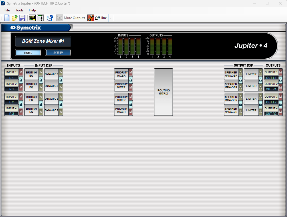
The Routing Matrix:

And the Priority Mixers:

The channels have already been labeled for this tech tip and we can see that there are two stereo inputs and two stereo outputs; noted as L/R 1, L/R 2, as well as Out L/R 1 and Out L/R 2 respectively.
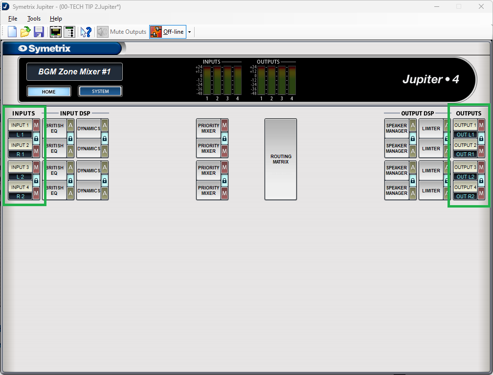
Also notice that all of the “lock” buttons have been engaged, locking channels 1 and 2, and 3 and 4. This is key to getting the proper control for stereo source select and volume control.
Open up Priority Mixer 1. Notice that the title of this page says “Priority Mixer 1/2”. This is noting that Priority Mixers 1 and 2 are linked, so actions in one affect the other.
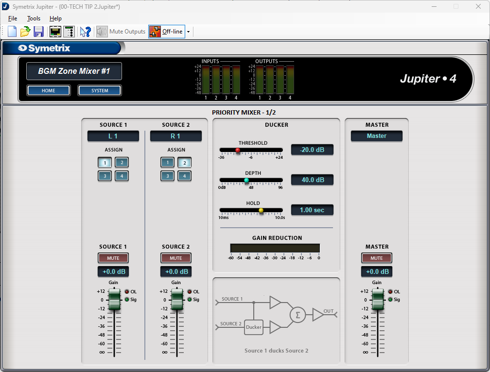
Note that Source 1 assign button has input 1 (L1) selected and its fader is at 0dB (we won’t be focusing on Source 2 in this Tech Tip). Now open up Priority Mixer 2.

We see that it has the same page name, Priority Mixer 1/2, and that the fader position is the same at 0dB, but the assign button is set to input 2 (R1). This represents that Priority Mixer 1 has input 1 (left) selected and Priority Mixer 2 has input 2 (right) selected. Change the assign button to input 4 and move the fader to the Off position. Now go back and look at Priority Mixer 1.
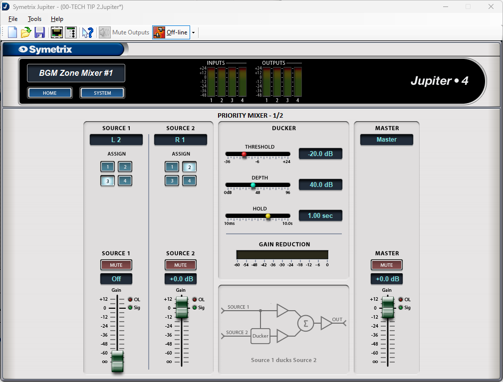
We see that the assign button has changed to input 3 (L2) and the fader has moved from 0dB down to the off position. This is what linking the two channels does.
Note: Odd number priority mixers should only select odd numbered assign buttons, while even numbered priority mixers should only select even numbered assign buttons. Reversing these will technically work, but the other locked priority mixer will do the opposite. For example, if priority mixer 1 selected input 2, then priority mixer 2 would select input 1.
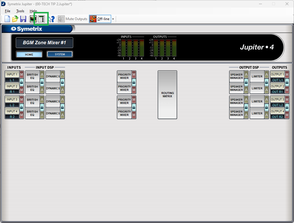
Now that we have an understanding of how the source selection works within the priority mixers, go back to the home page and open the Routing Matrix.
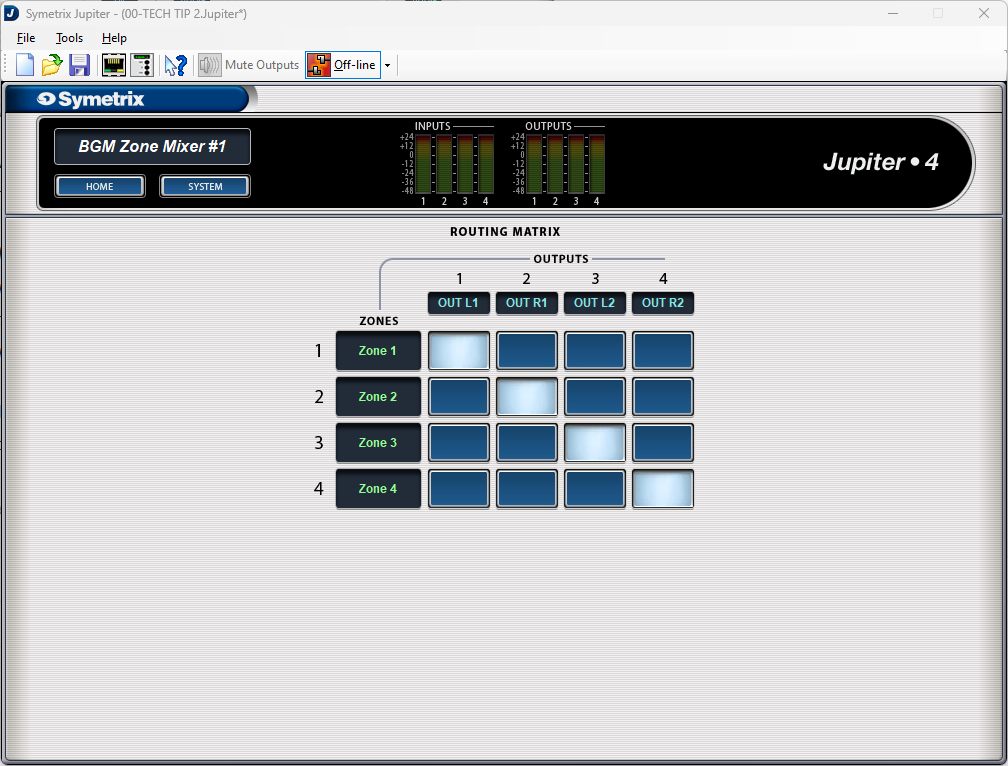
Notice that there are Zones labeled that connect to outputs through cross-points. These zones relate directly to the priority mixers; zone 1 is priority mixer 1, zone 2 is priority mixer 2, and so on. With the stair-step pattern of the cross-points, we can then say that Priority Mixer 1 is Zone 1 which is Output 1. The same for Priority Mixer 2, Zone 2, and Output 2, and the rest. For ease, you are welcome to relabel the zones to Priority 1, 2, and so on.
Now let’s set up the source select control. Go back to the home page and open up the External Controller Wizard.
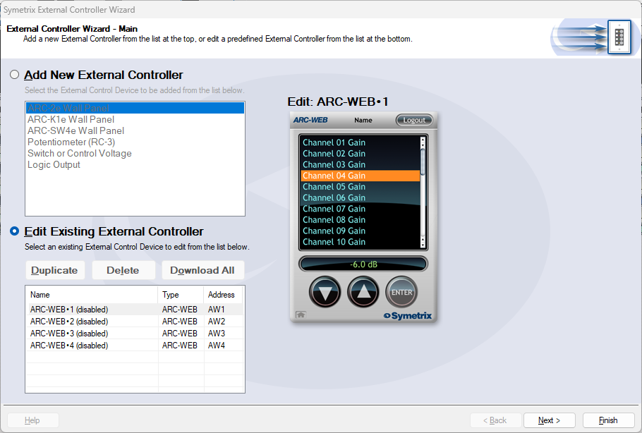
Select Edit Existing Controller, highlight an available ARC-WEB and click Next.
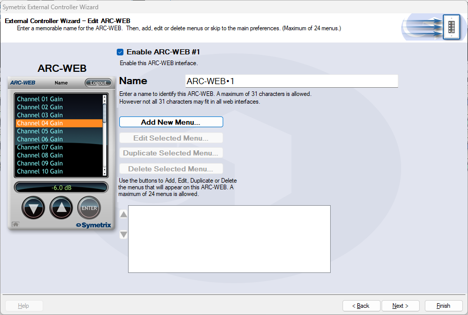
Enable the ARC-WEB at the top, rename the menu if necessary, and click Add Menu.
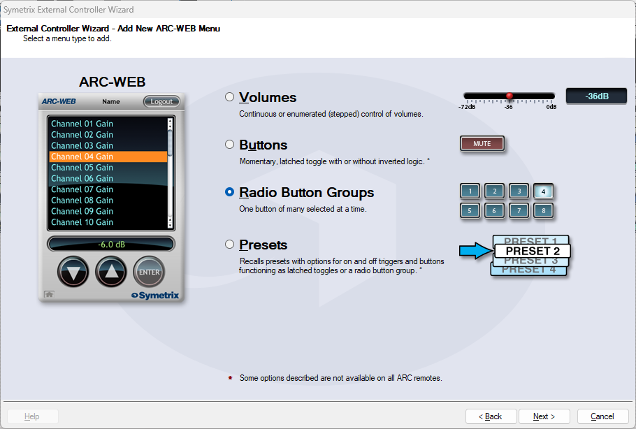
Select Radio Button Groups and click next.
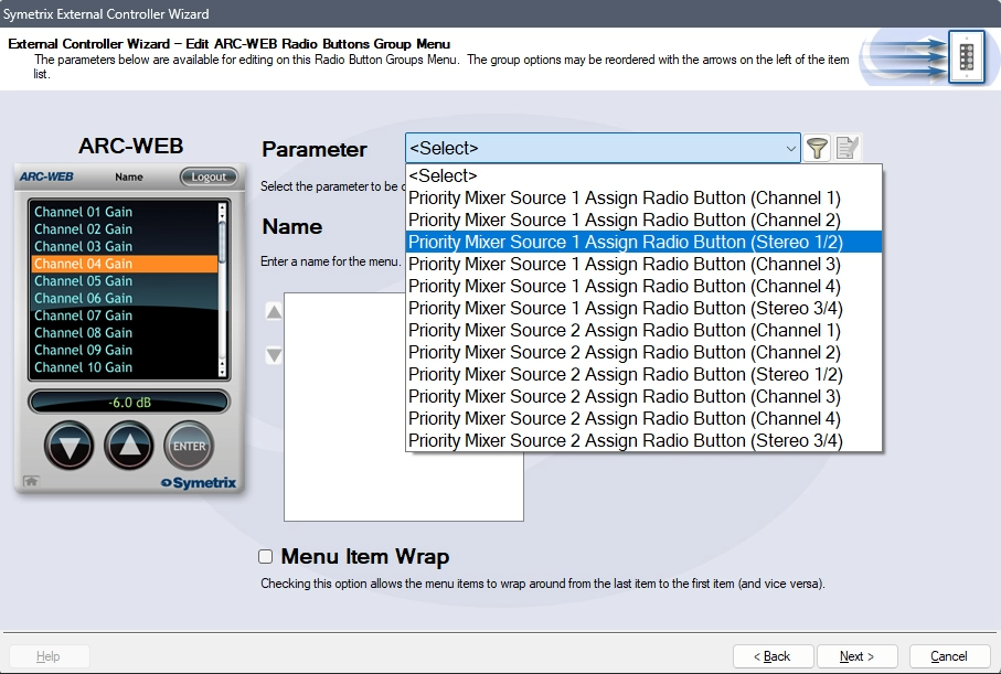
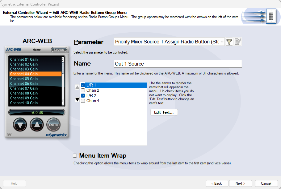
In the Parameter drop-down, select Priority Mixer Source 1 Assign Radio Button (Stereo 1/2). This will tell the Jupiter software that the source select will act in unison between Priority Mixers 1 and 2.
Name the menu appropriately. Remove options 2 and 4 from the channel list. This will prevent someone from accidentally reversing some inputs. In effect, there wouldn’t likely be a critical failure if this happened, however it is redundant and unnecessary to allow the Left audio channel to be in the Right output channel, and vice versa.
Re-name Chan 1 and 3 appropriately. In this case we’ll just use L/R 1 and L/R 2, but this could be a bluetooth source, third-party media player, or other stereo source. Since the Priority Mixers are acting together, Chan 2 and 4 are not necessary. Then click next.
We are brought back to the menu home page. Click Add New Menu to add a Volume Control. This time, choose volumes and click next.

Select Continuous or Enumerated appropriately and click next.
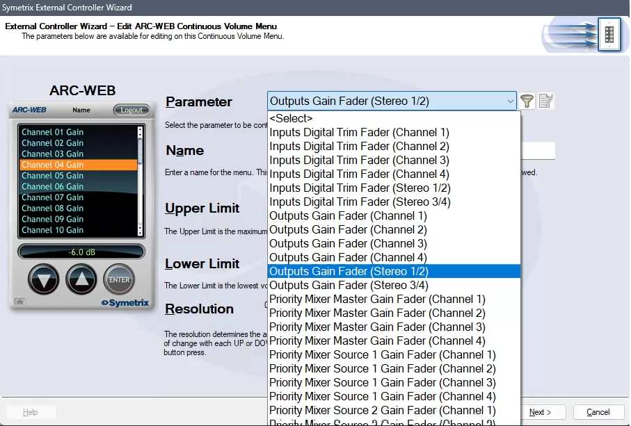
In the Parameter drop-down, select Outputs Gain Fader (Stereo 1/2). This will control the two gain faders for analog Outputs 1 and 2.
Note: While this is not the recommended parameter to control zone volume (as it is post-limiter and can put the sound system at risk of being overdriven with signal), there is not currently a way to control the faders from two Priority Mixers with ARC-WEB or ARC-2e by selecting one of them above. Consider setting the upper limit to the output fader control to prevent the overdriving of the amps/speakers downstream.
Name the menu and set the limit parameters appropriately and click next.

We are again brought back to the menu home page with two menus listed for source and volume control. Now we can test our work by clicking next and setting parameters along the way, until we arrive at the page that allows us to Launch ARC-WEB.
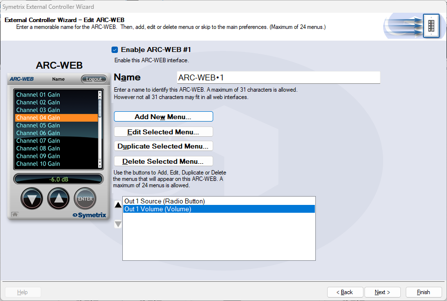
Click launch and a Browser window should open with your ARC-WEB where you can test the source selection and volume control. You must be online with the Jupiter DSP to test this programming. Programming for ARC-2e will allow for a simulator interface that can be tested with.
By using SymNet Designer, the entire line of Symetrix Modular ARC panels can be made to control any parameter within your Jupiter device beyond those already available in the External Controller Wizard. You can also utilize expansion ARCs such as the EX4 and EXK giving you even more possibilities. Here’s
how:
1) Connect the ARC and host PC to your Jupiter device.
2) Launch the latest version of the Jupiter software and discover the device on your network using the Connection Wizard. After completing the Connection Wizard, take note of the IP address of the Jupiter device. Perform a firmware upgrade if necessary.
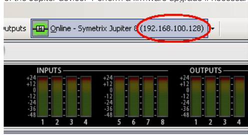
3) Ensure you can communicate with the ARC using the External Controller Wizard. Upgrade the ARC firmware if necessary.
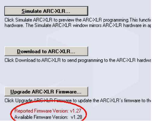
4) Go to the Tools menu and choose Store Preset. Click Custom Preset and Choose parameters. From within this dialog browse to the control(s) you wish to access from the ARC and write down the controller number (far right column).
5) Launch the latest version of SymNet Designer. Go to the File menu and choose Preferences. Under Communications Mode choose Use LAN (Local Area Network) and then click OK
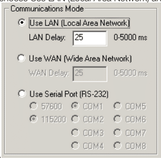
6) Go to the Edit menu and choose Site Ethernet Preferences. Click on Ring #1 and then click Edit Unit Settings. Enter the IP information of the Jupiter device. Then click OK, then Done.
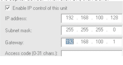
7) To ensure that SymNet Designer is communicating with the Jupiter device over IP go to the Hardware menu and choose Upgrade Firmware/Hardware Settings. Look for the name of the Jupiter device listed under Hardware. If it shows Not Present, then double check the IP address of the Jupiter and return to step 6. *Note, do not upgrade firmware or take any action from this dialog.
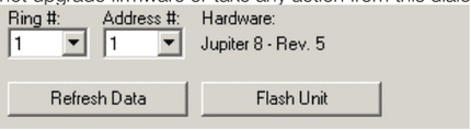
8) To ensure that SymNet Designer is communicating with the Jupiter device over IP go to the Hardware menu and choose Upgrade Firmware/Hardware Settings. Look for the name of the Jupiter device listed under Hardware. If it shows Not Present, then double check the IP address of the Jupiter and return to step 6. *Note, do not upgrade firmware or take any action from this dialog.
9) Now that we’ve established communication, let’s program the ARC. Go to the Tools menu and choose Controller Manager. Click New RS-485 Device and choose the appropriate ARC.
10) Edit the newly created ARC and enter the controller numbers (noted from step 7) in the appropriate sections of the Edit Modular ARC menu, i.e., Switches, Knobs, etc. When all controller numbers have been added to your ARC, download to the ARC from within the Controller Manager. This will send the programming to the remote. If it will not download, double check that the RS-485 address shown on the rotary dipswitches on the back of the ARC match the address in the Edit Modular ARC menu.
11) Finally, with the Jupiter software in focus, test the controls on the ARC and watch for the Jupiter GUI to follow those control changes. Note, custom programmed ARCs will not appear in the Jupiter External Controller Wizard and you must ensure that all ARCs on the network have unique RS-485 addresses regardless of how they were programmed.
This is a general-purpose step-by-step guide for connecting to Symetrix digital signal processors and related hardware with a PC. Please note that Symetrix only recommends using Windows 10 and above. Other operating systems are not officially supported at this time.
Step 1 – Install the right software for the device
Symetrix site design software is used to connect to Symetrix devices and is available to download, install, and run for free. The required software will depend on the devices that needs to be accessed:
Composer:
Current Symetrix open-architecture DSPs all use Composer, which can be downloaded here. These include:
- D100
- Radius
- Prism
- Edge
- Solus NX
Other Symetrix hardware that can be accessed through Composer will include:
- Endpoints and expanders (xIn, xOut, and xIO devices)
- T Series touch panels
- W Series wall remotes
- Control expanders (xControl, Control Server)
Important: To avoid errors when going online with the hardware, please download the version of Composer that matches the DSP’s firmware revision number as closely as possible. This number can be found by cycling through the system pages on the front LCD panel of the DSP.
Integrator Series:
Software for Symetrix’s current Integrator Series (closed-architecture) DSPs can be downloaded here. These include:
- Jupiter
- Zone Mix 761
Legacy Hardware:
Legacy open-architecture DSPs such as 8×8 DSP, Express CobraLink, and original Solus (non-NX) require SymNet Designer. This software has been discontinued and is no longer supported by Symetrix, but the final version (10.7) can be downloaded here. Software for all other legacy products, such as Zone Mix 760, AirTools-series, and Lucid-series, is no longer available for download.
Step 2 – Make sure the PC is on the right network
Once the correct software has been downloaded, the next step is to connect the PC to the device’s control network. If a DSP is Dante-enabled, make sure not to confuse the Dante ethernet port for the control ethernet port. Configuration of these devices through the Symetrix software is always done through the control port.
By default, Symetrix devices will obtain an IP address automatically, either from a DHCP server or, if a DHCP server is not available, by obtaining a link-local (169.254.x.x) IP address. Most Composer-enabled devices will display their IP address on the front LCD panel. Cycling through the system pages on the front LCD will additionally display the subnet mask. If a device has previously been configured with a static IP address, it can be reset to DHCP by briefly pressing the device’s reset button, which is usually recessed in the housing on the back of the device.
ncpa
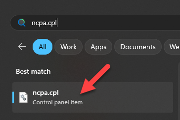
It is important that the PC’s network settings match those of the devices being used in the system. To check this, enter ‘ncpa.cpl’ in the Windows search bar to open the list of network adapters on the PC:
Right click the network adapter that will be used to connect to the device, select ‘Properties.
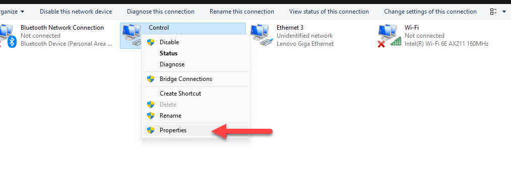
version
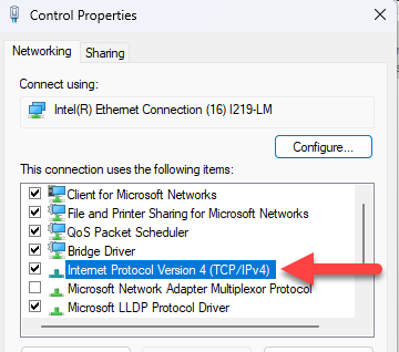
Then double click ‘Internet Protocol Version 4’:
address
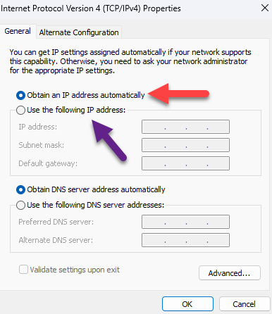
The network settings of the PC’s network adapter will display. If the Symetrix device is set to DHCP, select ‘Obtain an IP address automatically.’ Alternatively, a static IP address and custom subnet mask can be set here:
Important: Ensure that both the IP subnet and subnet mask of the network adapter match that of the device. If setting the PC to a static IP address, it must be a different/unused IP address on the network. If connected directly to the DSP with a static IP address, setting the PC to an address “right next to” the DSP usually safe. Example; if the DSP IP address is 192.168.100.50, set the PC to 192.168.100.51.
Step 3 – Locate the Symetrix hardware on the network
Once the PC is on the correct network, open the appropriate Symetrix software. The next steps will depend on the software being used.
Composer:
site
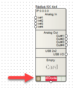
If a copy of the site file is available on the PC: Select the ‘File’ menu > Open and select it from File Explorer. In Site View, all located devices will have a checkmark in the lower left corner. If there is no checkmark present, click the empty box in the lower left corner of the device to open the Locate Hardware menu:
In the Locate Hardware menu, a list of available devices will appear. If necessary, click ‘Select Network to Search…’ to ensure that the correct network adapter is being used to scan for devices. Either double click the device in the list or highlight it and select ‘Locate to Selected Hardware’ to finish locating the device:
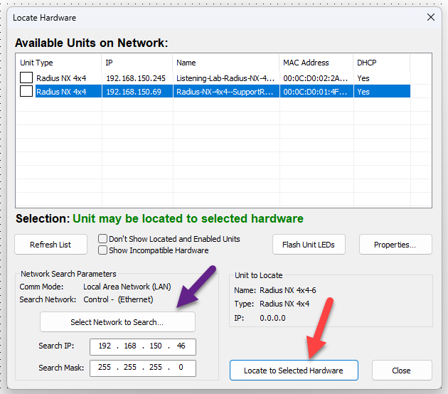
Repeat the above process for all devices in the Site View.
If the site file needs to be pulled from the unit:Go to the ‘Hardware’ menu > ‘System Manager’ > ‘Hardware’ tab. A list of all available units on the network will display. If needed, click “Select Network to Search…” to change the network being scanned for devices. Highlight the desired unit, then select ‘Go Online (Pull from Unit…)’:
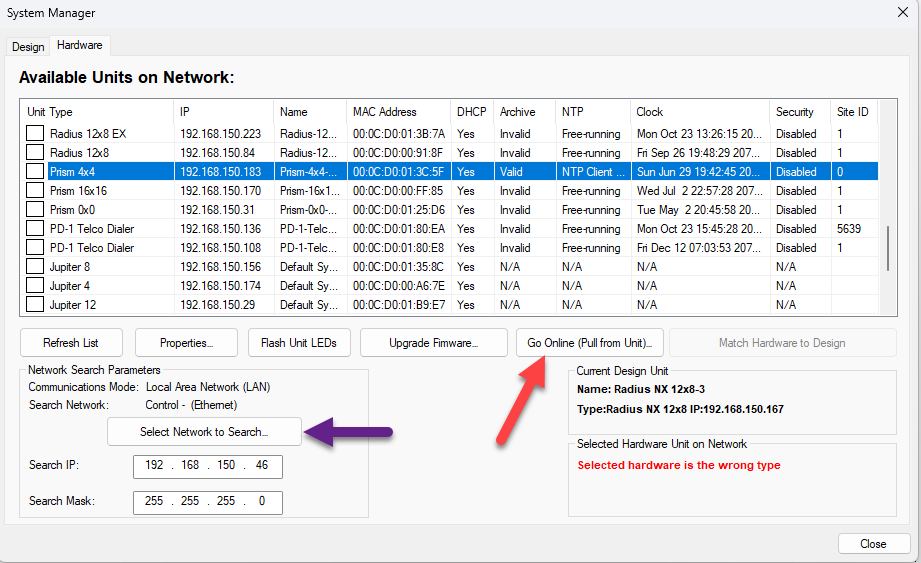
The Pull Site File From Hardware Wizard will appear. Select a location on the PC where the site file will be saved, then click ‘Next’:
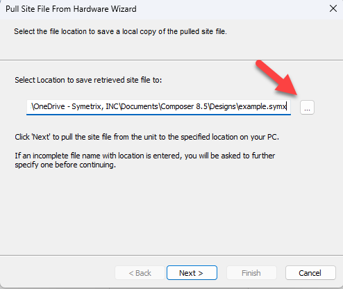
Next, select either ‘Yes – Synchronize to All Changes’ to keep any changes made to the configuration while last online with this site file, or ‘No – Abandon Changes’ to revert to the archived version of the site file. ‘Show Advanced Options’ allows for more granular control over which changes are kept when synchronizing:
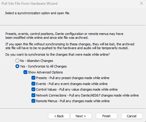
Select ‘Next’, then either select ‘Finish’ to go online with the site file as-is or select ‘Cancel’ to make changes to the site file before going online:
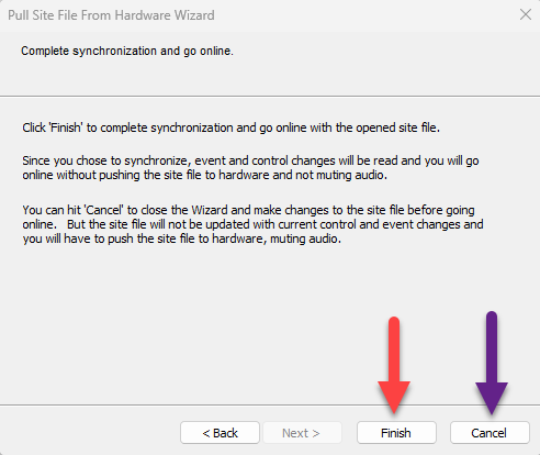
A note about Dante devices– Any Dante devices in the design must be located through a Symetrix DSP that has already been located:
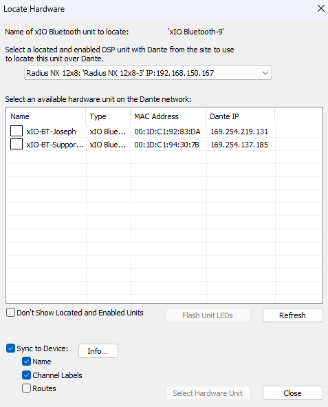
As of Composer 8.5, an xIO Updater/Configurator module may be added to the site view to configure Symetrix xIO Dante devices if a Symetrix DSP is not available. Symetrix recommends using separate networks for Dante and control.
Integrator Series:
Locating an Integrator Series DSP is done in the Connection Wizard of the Jupiter or Zone Mix 761 software. This can be done either by selecting ‘Existing File on Device’ > ‘Open Connection Wizard’ from the startup menu, or by selecting the Connection Wizard icon in the top ribbon:
Once the Connection Wizard opens, select the option that best fits the connection type, then select ‘Next’. A list of the PC’s network adapters will appear. Select the one that is connected to the ethernet port of the device, then select ‘Next’. Select ‘Open Network Connections’ to show these network adapters in Windows Control Panel if any settings need to be changed:
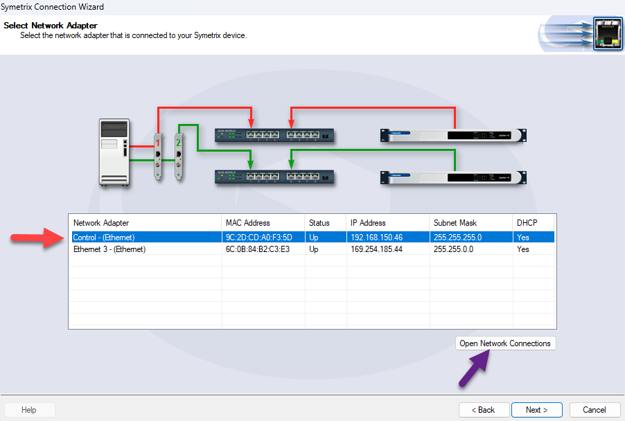
A list of devices will appear. Any devices not compatible with the current site file will be grayed out. Select the device, then select ‘Next’. Selecting the ‘Properties…’ button will allow a static IP address to be set for the device if desired:
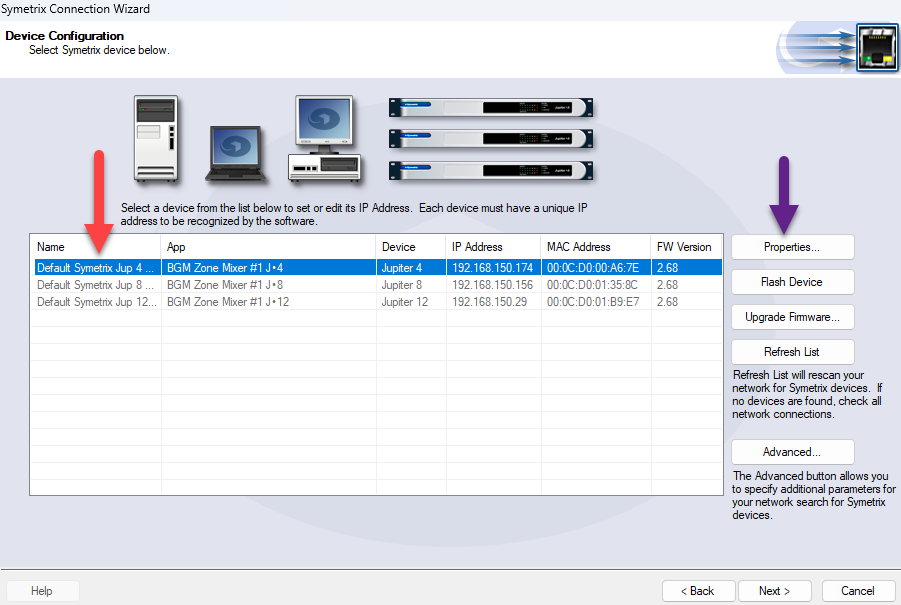
On the final screen, select ‘Finish’ to close the Connection wizard. To go online immediately, ensure the ‘Go online now’ box is checked:
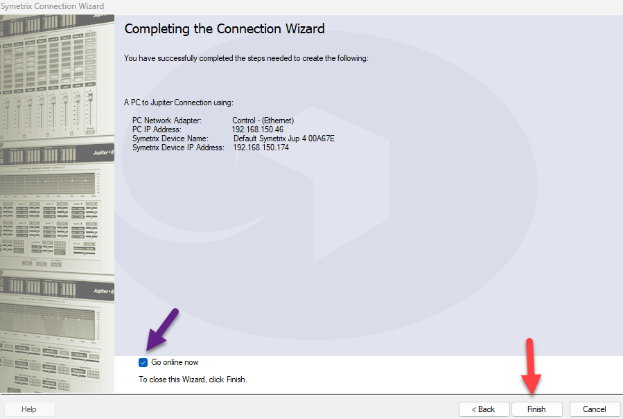
Step 4 – Go online with the system
Composer:
online
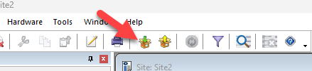
Once all devices in the site file have been located, select ‘Go online (push site file to hardware)’:
Note: The icon with the yellow arrow is for pulling the site file from the located hardware. Please see the passage entitled “If the site file needs to be pulled from the unit” in the previous section for more information on pulling the site file from the hardware.
Next, the Site Preferences window will appear. These are generally advanced options that can be left alone, however if Dante routing is being managed in Dante Controller rather than in Composer, uncheck the box next to ‘Configure Network Audio.’ Click ‘OK’ to proceed:
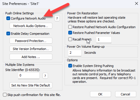
dialogue
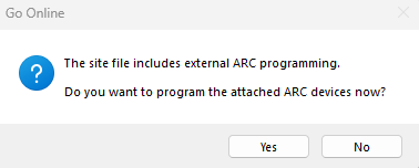
At this point, if the site file has not yet been saved to the PC, the File Explorer will appear and prompt for a filename and location to save the file to. If any ARC remotes are present in the design, a dialogue will appear and ask if all remotes should be programmed now. Regardless of whether ‘Yes’ or ‘No’ is selected here, the system will continue to push and go online:
success
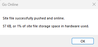
Once the site file has been successfully pushed, a success dialogue will appear. After clicking ‘OK’, the system volume will gradually ramp up unless the system mute is engaged:
Now that the system is online, parameters can be changed in real time, and signal meters will display their data. However, if any modules are moved, added, or deleted, or if any wires are changed, the system will automatically go offline. The site file must be re-pushed in order to go back online.
Important: The firmware versions of all devices in a Composer site file must match the version of Composer being used before going online with the system. If this is not the case, a message will appear prompting a firmware upgrade before the system can go online. Please refer to the Updating Firmware with Composer Tech Tip for further assistance.
Integrator Series:
After finishing the Connection Wizard, select the orange ‘Off-line’ button in the top ribbon. The drop-down arrow can be selected to choose which previously located device to go online with:
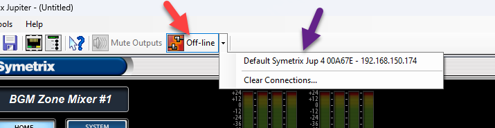
A prompt will then appear allowing the user to select whether to push the currently open configuration file to the device, or to pull the configuration file off of the device and save it to the PC.
Once the system is online, parameters can be changed in real time, and signal meters will display their data.
Integrator Series devices will operate normally with the factory firmware and should not require firmware updates to go online.
FAQs and Troubleshooting
“My device does not appear in the Locate Hardware menu.”
- Double check that the PC’s NIC and the Symetrix device are on the same network.
- Double check that the selected network in the Locate Hardware menu corresponds to the intended NIC.
- Change all octets of the IP address and subnet mask being searched for to ‘255’, uncheck the box next to ‘Don’t show located and enabled units’, and check the box next to ‘Show incompatible hardware’ in order to broaden the search as widely as possible.
- If a USB to ethernet adapter is being used with the PC, connect using a standard ethernet port instead if possible.
- Power cycle both the PC and the device.
- Re-seat the ethernet cable in both the PC and the device.
- Try a different ethernet cable.
- If the device is connected to the PC through a network switch, try a different switch port, or connect directly to the PC instead.
- If all else fails, disconnect the device from the network, reset its network settings by tapping the reset button once, then directly connect it to the PC (ensuring the PC is set to automatically obtain an IP address).
“I’m getting a ‘Failed to go online’ error message.”
- Disable Windows Defender Firewall and any third-party antivirus/firewall programs that may be blocking network traffic.
- Double check that the device firmware versions for all devices in the site file match the version of Composer being used (the first two numbers are most important).
- Power cycle both the PC and the device.
- If the device is connected to the PC through a network switch, try connecting directly instead.
- If a device cannot be located and is not needed in the site file, right click it and select ‘Disable Unit’.
“I can’t locate my Dante device.”
- Double check that the DSP is Dante-enabled by going to the ‘Tools’ menu > ‘Launch Remote Terminal’ > ‘Options’ menu > enable ‘Debug Mode’, then send the command info cards to the IP address of the DSP. If ‘Non-Dante Clock Card’ is displayed in the output under ‘Audio Network Card’, then the device does not have a Dante card installed. Please contact sales@symetrix.co to purchase one. If ‘No Card Present’ is displayed instead, there may be a problem with the Dante card.
- Double check that the Dante device is connected to the Dante port of the DSP.
- Connect the Device directly to the DSP’s Dante port, bypassing any network switches. If it can be located using this method, there may be a problem with the network.
- If all else fails, connect the PC to the Dante network, or directly to the Dante device, and verify that it appears in Dante Controller. If not, then there may be a problem with the Dante device, or it may be set to a static IP address outside of the Dante network.
“What does the yellow checkmark next to a device in Composer mean?”
A yellow checkmark means that the device is muted, while a green checkmark means that the device is unmuted.
Connecting ARCs to Jupiter hardware is simple using the (RJ-45) ARC port on either the front or back of the device. These ports not only provide communication (RS-485) data, but also +24 VDC power. If the required number of ARCs exceeds the current limits of the Jupiter ARC port(s), an ARC-PS can be used to power additional ARCs. Connecting a Jupiter ARC port to the RS-485 port on the ARC-PS is easily accomplished by following one of two methods.
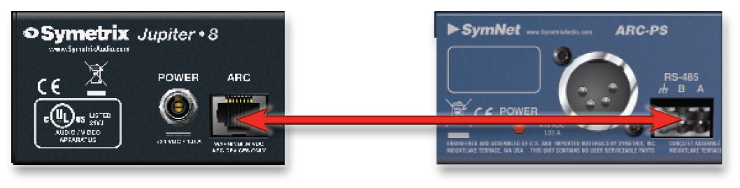
Method 1: Modify an Off-the-Shelf CAT-5 cable
- Cut off one end of the CAT-5 cable.
- Wire three of the wires to a terminal block connector such that:
A = Blue.
B = Blue/White.
Ground = Green.
Note: Blue/White is twisted with Blue, and Green/White is twisted with Green. - Connect the RJ-45 to the ARC port on Jupiter.
- Connect the terminal block connector to the RS-485 port on the ARC-PS.
- Connect your ARCs to the RJ-45 ports on the ARC-PS.
- Program your ARCs with the External Controller Wizard in the Jupiter software.
Method 2: Make Your Own Cable
- Crimp an RJ-45 connector to one end of a CAT-5 cable.
Note: Only pairs 4+5 and 3+6 are necessary, so STP cable could be
substituted by sharing the ground. - Wire three of the wires to a terminal block connector such that:
A = pin 4.
B = pin 5.
Ground = pins 3 and 6. - Connect the RJ-45 to the ARC port on Jupiter.
- Connect the terminal block connector to the RS-485 port on the ARC-PS.
- Connect your ARCs to the RJ-45 ports on the ARC-PS.
- Program your ARCs with the External Controller Wizard in the Jupiter software.
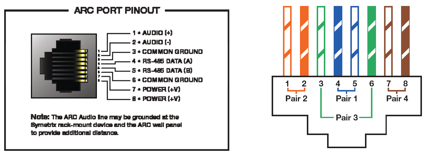
NOTE: Refer to the ARC Network Design topic in the Jupiter help file for more information.
This document describes how to control Symetrix Jupiter and Zone Mix 761 products over the Internet or other wide area network (WAN) using port forwarding. It discusses the necessary ports that need to be opened to enable access to Jupiter and Integrator Series devices It also discusses alternative ways of control and gives some general network background information.
Quick Summary of Required Port Forwarding
If you already have a good understanding of firewalls, port forwarding, and NAT and don’t want to read this entire document, refer to the table below for a quick list the ports required to be enabled for remote control of Jupiter or Integrator Series products.
| Usage | Protocol/Port | Notes |
| ControlNet Discovery | UDP 49216 | Broadcast Packet used by Connection Wizard |
| ControlNet Control Data | UDP 49184 | Controller changes, meter data, etc. |
| ControlNet String Data | UDP 49344 | Channel names, etc. |
| SymNet Designer Communications | UDP 8000 | Used for routine polling of device parameters, ARC programming, etc. |
| FTP control stream | TCP 21* | Passive FTP mode is used |
| FTP data stream | dynamic | Most firewalls automatically handle the data port without an explicit rule |
| Remote Terminal | 486300 | Not recommended unless remote troubleshooting or remote control systems are required |
*Most routers and firewalls have a built-in rule for FTP. Whenever possible, this should be used instead of a manual rule for TCP port 21
Step-by-Step Instructions
Below are step-by-step directions for enabling and using port forwarding for a Jupiter or Integrator Series device.
- Obtain the public/external IP address of the Symetrix device using a web site such as http://www.whatismyip.com or by contacting the ISP of the site.
- Obtain the private/internal IP address of the Symetrix device by running the Connection Wizard with an on-site computer. The PC running the wizard must be on the same LAN as the Symetrix device.
- If the Symetrix device is using DHCP to obtain its IP address, we recommend changing to a static IP address. This will ensure that its address remains the same, which is necessary for the port forwarding rules to work properly. Alternatively, most DHCP servers can be configured to permanently assign the same IP address to a given device using “reservations”.
- On the site’s router or firewall, set up port forwarding rules from the public IP address to the private IP address. Create the rules for all ports listed above.
- From off-site:
SymNet Designer- Run the Connection Wizard (SymNet Designer) to find the device. On the Device Configuration page, click the Advanced button. Enter the Symetrix device’s public IP address in the Search IP Address Base. Enter 255.255.255.255 for the Search subnet mask.
Press OK.
SymNet Composer- Open the Locate Hardware. Enter the Symetrix device’s public IP address in the Search IP Address Base. Enter 255.255.255.255 for the Search subnet mask. Click Refresh List. Select unit and press Select Hardware Unit. - At this point, the Connection Wizard should be able to see the remote device. If so, select it and Finish the wizard.
- You can now go on-line with the device just as if you were connected locally.
Ports and Protocols
Jupiter and Integrator Series products use a variety of Ethernet ports and protocols for communication and control. All communications are Ethernet-based using the IP protocol. Both TCP/IP and UDP/IP connections are used. For a successful remote connection, all of the required ports must be available. The following sections describe each of the communication types used.
ControlNet
ControlNet is a suite of protocols designed by Symetrix for efficient low overhead communication. It allows controlling and monitoring audio parameters and metering signals in real time. ControlNet also allows keeping string data such as channel names in sync between software applications and devices. There are 3 separate UDP-based protocols that make up the ControlNet suite: Discovery, Control Data, and String Data.
ControlNet Discovery
ControlNet Discovery is used to find or “discover” devices without knowing their IP addresses. It uses broadcast UDP packets. All connected devices respond to Discovery request and inform the requester of their name and IP address. Discovery is used in the Connection Wizard. In this case, the Connection Wizard running on the PC sends out the Discovery request, and the hardware devices respond. Discovery uses UDP port 49216 on the devices.
ControlNet Control Data
Control Data packets are the workhorses of ControlNet. They are used to send and receive parameter changes and meter updates. When you move a fader or push a button in a Jupiter or Integrator Series GUI, the Control Data protocol makes the changes. Control Data uses UDP port 49152 on the
devices.
ControlNet String Data
String Data packets are used to send text strings between devices and the GUI. They are used on the Automix Matrix 780 and other products to keep channel names, etc. in sync between the hardware and software. String Data uses UDP port 49344 on the devices.
FTP
FTP or File Transfer Protocol is a standard method used to transfer files between two devices. In the Jupiter and Integrator Series software, FTP is used primarily when transitioning between on- and off-line and upgrading firmware. For example, FTP is used to send your device file to the actual device for storage. Later, it can be retrieved from the device again using FTP. FTP uses TCP port 21 on the device for control. It also opens a second TCP port for data streaming. However, the second port is usually handled transparently by firewalls and routers.
Remote Terminal
This protocol is typically used by AMX, Crestron, or other third-party control systems. These controllers are almost always local to the device, so making them available over the Internet isn’t required. However, this protocol can also be used for troubleshooting, typically under the direction of tech support.
Making this protocol available can allow this should the need arise. However, this is the least secure protocol, so caution is advised.
Port Forwarding
Port forwarding is the process of forwarding network traffic on specific ports destined for a public IP address to a private IP address. This allows certain types of traffic to be directed to the Jupiter or Integrator Series device, while other types can be sent to other equipment (for example, HTTP traffic to a web server). All the determination of which device receives each inbound network packet is based on the TCP/IP or UDP/IP destination port of the packet, hence the term “port forwarding”. To control a Symetrix device, all the ports used by the Jupiter or Integrator Series software must be forwarded to the device.
The tables below show which ports need to be forwarded. There are three different versions with trade-offs between simplicity, security, and future compatibility.
Table 1: Minimal Port Forwarding, maximum security
This port list opens the fewest number of ports. This is the recommended setting for most users.
| Usage | Protocol | Port |
| ControlNet Discovery | UDP | 49216 |
| ControlNet Control Data | UDP | 49184 |
| ControlNet String Data | UDP | 49344 |
| FTP | TCP | 21* |
Table 2: Future-proof Port Forwarding
This port list opens additional ports that may be used in future versions of Symetrix devices.
| Usage | Protocol | Port |
| ControlNet Discovery | UDP | 49216-49247 |
| ControlNet Control Data | UDP | 49184-49215 |
| ControlNet String Data | UDP | 49344-49375 |
| FTP | TCP | 21* |
| Remote Terminal | UDP | 48630 |
Table 3: Future-proof Port Forwarding
This port list opens additional ports that may be used in future versions of SymNet Composer devices.
| Usage | Protocol | Port |
| ControlNet Discovery | UDP | 49216-49247 |
| ControlNet Control Data | UDP | 49184-49215 |
| ControlNet String Data | UDP | 49344-49375 |
| FTP | TCP | 21* |
| Remote Terminal | UDP | 48631 |
Table 4: Future-proof Port Forwarding
This port list opens additional ports that aren’t needed, but requires the fewest rules, so is easiest to set-up.
| Usage | Protocol | Port |
| ControlNet Suite | UDP | 49184-49375 |
| ControlNet Control Data | UDP | 8000 49472 |
| FTP | TCP | 21* |
*Most routers and firewalls have a built-in rule for FTP. Whenever possible, this should be used instead of a manual rule for TCP port 21
Active vs. Passive FTP
To make an FTP connection, the server needs to know on which port to talk to. In active FTP, which was designed before firewalls were common, client tells the server “this is the port you should talk to me on,” and the server attempts to connect to that port. This is like client giving the server a phone number to
call your computer at. The firewall blocks incoming calls, so you get an error when trying to open a connection because client never hears from the server.
The client connects from a random unprivileged port (N > 1023) to the FTP server’s command port, port 21. Then, the client starts listening to port N+1 and sends the FTP command PORT N+1 to the FTP server. The server will then connect back to the client’s specified data port from its local data port, which is port 20. From the server-side firewall’s standpoint, to support active mode FTP the following communication channels need to be opened:
- FTP server’s port 21 from anywhere (Client initiates connection)
- FTP server’s port 21 to ports > 1023 (Server responds to client’s control port)
- FTP server’s port 20 to ports > 1023 (Server initiates data connection to client’s data port)
- FTP server’s port 20 from ports > 1023 (Client sends ACKs to server’s data port)
In passive FTP, client asks the server to pick a port, and then connects to the server on that port. This is like client asking at what phone number it can call the server. Since client makes the call, the firewall allows it, and you are all set to transfer files.
The client initiates both connections to the server, solving the problem of firewalls filtering the incoming data port connection to the client from the server. When opening an FTP connection, the client opens two random unprivileged ports locally (N > 1023 and N+1). The first port contacts the server on port 21, but instead of then issuing a PORT command and allowing the server to connect back to its data port, the client will issue the PASV command. The result of this is that the server then opens a random unprivileged port (P > 1023) and sends P back to the client in response to the PASV command. The client then initiates the connection from port N+1 to port P on the server to transfer data.
From the server-side firewall’s standpoint, to support passive mode FTP, the following communication channels need to be opened:
- FTP server’s port 21 from anywhere (Client initiates connection)
- FTP server’s port 21 to ports > 1023 (Server responds to client’s control port)
- FTP server’s ports > 1023 from anywhere (Client initiates data connection to random port specified by server)
- FTP server’s ports > 1023 to remote ports > 1023 (Server sends ACKs (and data) to client’s data port)
SymNet software operates in Passive Mode.
Security Considerations
By setting up port forwarding for a Symetrix device, you are making it visible on the global Internet, opening up potential security issues. However, you do have one measure of security, the so-called “security by obscurity”. Unless someone else knows the IP address and listening ports of your device, it can’t connect to it. This isn’t foolproof but does reduce the risk of hacking.
Another aspect of security by obscurity is that the Symetrix-specific protocols described here aren’t well known. Hackers tend to concentrate on familiar protocols such as HTTP, FTP, and Telnet. Of course if you were paying attention above, you noticed that Jupiter and Integrator Series devices use FTP. This is probably the biggest security risk. The FTP connection does require a valid user-name/password combination, so this provides some protection.
To further minimize security risks, you can set up your port forwarding rules to allow only connection from a specific IP address. For example, if you always access the device from a corporate PC which has a static IP address, you can limit connection to just that (public) IP address. Keep in mind that this would prevent you from accessing the device from home, or a WiFi hotspot on the road.
Symetrix offers hardware-based security, which covers the ability to connect and control a device with the Symetrix software. This should definitely be turned on for a device visible on the Internet. However, even though this prevents connection from the Symetrix software by securing the SymNet Designer protocol, it doesn’t protect other protocols such as ControlNet and Remote Terminal. In particular Remote Terminal is unsecured and has the power to do serious damage to a device. Probably the best way to ensure security is to use a VPN connection, as described below.
Testing and Trouble-shooting
After setting up port forwarding for remote access, use these guidelines to test and trouble-shoot the connection. The primary tool for testing is the Connection Wizard. Ideally there should be someone on site to make any required changes.
- Run the Connection Wizard and try to locate your device. If it appears, ControlNet Discovery is working properly. If not, verify you are using the correct external IP address (in the Advanced dialog box) and that the port forwarding rule for Discovery is properly configured and enabled.
- If you can discover your device, push the Flash Device button. If someone locally can verify the front panel LEDs are flashing, communications are working properly. If not, verify a port forwarding rule
for UDP port 8000 to the private IP address of the Symetrix device is properly configured and enabled. If no one is available locally to visually verify the flashing LEDs, it is possible to determine if this works from the application. After pressing the Flash Device button, note how long it takes before you can click on other buttons. If control returns within 1-2 seconds, it is working. If it takes 10 seconds or more, it isn’t working. Some versions of the Wizard will indicate success of the command directly with a pop-up “balloon” message. - Press the Properties button. This will use FTP to read the device properties. If the Device Properties dialog comes up within a few seconds, FTP is working properly.
- Try going on-line with the device. If the above three steps work, you should be able to go on-line. If you aren’t able to, see the discussion of latency below.
Latency Issues
When controlling a Jupiter or Integrator Series device over a local area network, packets typically travel between the PC and the device in a few milliseconds. However, over the Internet the latency is much larger, often hundreds of milliseconds. Most of the protocols used in Symetrix devices are relatively insensitive to increased latency, with the only affect being slower response to changes. However, the SymNet protocol requires a response to every command and assumes a low latency connection. If there is a problem with latency, you may find you can connect to a device initially, but it drops off-line shortly thereafter.
To fix this, there is a registry setting available to tell the software to “wait longer” before giving up on SymNet commands. The setting is called “ConnTimeout” and is located in HKEY_CURRENT_USER\Software\ Symetrix\\Connection (note that are specific the software you are using, e.g. “ZoneMix 760 2.5”. The default value is 50 (milliseconds). If you are having trouble staying on-line or know your latency is significantly longer than 50 ms, increase this value. Be sure to make all changes while the Jupiter or Integrator Series software is not running.
To measure the latency between your PC and the Symetrix device, you can use the “ping” command from a command prompt. The command “ping ” will tell you the round-trip delay. We recommend using a value slightly larger than the reported maximum round-trip time.
Note that the actual bandwidth of the connection (megabits per second) is less important than the latency for the responsiveness of a remote connection. As long as the latency is low (i.e. < 30 ms), the responsiveness can be very good even with a relatively slow 1 Mbit/second connection.
Special Cases
Controlling Multiple Jupiter or Integrator Series Devices at the Same Site
Jupiter and Integrator Series devices don’t support controlling multiple units with the same public IP address via port forwarding. It is possible to discover multiple units behind the same public address, but connecting requires a dedicated public IP address for each device. If multiple public IP addresses are used, you should set up duplicate port-forwarding rules for each device/public IP address pair. Each set of rules would map a single public IP address to a single private IP address for a Symetrix device. Another option is to use a VPN connection, as described in Other Control Methods.
Site Contains an Externally Accessible FTP Server
If a site contains an FTP server accessible from the outside world, the firewall may already have a rule set-up to forward FTP traffic to the FTP server. This presents a problem in that FTP traffic from Jupiter or Integrator Series software will be sent to the FTP server instead of the device. To resolve this, you can either a) use multiple public IP addresses or b) use multiple port numbers for FTP.
In the first option, the FTP server and the Symetrix devices would each have their own public IP address. Then the firewall would have two separate rules for FTP and forward FTP traffic appropriately based on the public IP address. This is the most straight-forward solution, but may require contacting the site’s ISP
to arrange for the additional public IP address(es).
The second option is to change the port number used for FTP for one of the devices. FTP typically uses TCP port 21, but most FTP servers can be configured to listen on other port numbers. Jupiter and Integrator Series devices currently don’t support ports other than 21 for FTP, so the change must be made to the FTP server. After this is done, FTP users will need to specify this new port number for their connection, typically done by adding “:” after the URL. For example, if the previous URL for FTP was ftp.mysite.com and the new port number was 10021, the new URL would be ftp.mysite.com:10021.
Other Control Methods
In addition to the port forwarding method described above, there are a few other options for remote control of Jupiter or Integrator Series products.
Virtual Private Network (VPN)
If you can establish a VPN connection to the remote site, you should be able to connect to and control a Jupiter or Integrator Series device without any other set-up. As long as the VPN allows the network traffic listed above (which is generally the case by default), it should work just as if you were local. After establishing the VPN connection, run the Connection Wizard. On the “Select Network Adapter” screen, you should see an option for your VPN under Network Adapters. Select this and continue. The main advantages of this method are simpler set-up and configuration, improved security, and ability to access multiple Symetrix devices at the same site. The main disadvantage is the overhead of creating the VPN account, and potential security risks of a site giving an outside contractor VPN access to their internal network.
Static NAT
Also called “one-to-one NAT”, this method sets up a simple one-to-one mapping of a public and private IP address. Basically, any traffic destined for a particular public IP address is sent to a particular private IP address regardless of port. Using this method has the advantage of being easier to set-up since individual ports need not be configured. The disadvantage is increased security risks since all traffic will now be sent to the device. It also likely requires a dedicated static public IP address for the device, as opposed to port forwarding which allows sharing a public IP address with other equipment on site.
Remote Control of a Local PC
An entirely different approach is to maintain a PC on site with the Jupiter or Integrator Series device and then simply access and control that PC remotely (aka remote desktop). This reduces the problem to establishing a remote control connection, which is a very common task. This method is outside the scope of this discussion. But in brief, there are a variety of methods for establishing remote connections including web-based tools such as LogMeIn.com, GoToMyPC.com, the built-in Windows Remote Desktop, free tools such as VNC, and commercial products such as PC Anywhere. Some web conferencing solutions also include remote control features. An obvious disadvantage of this method is that a PC must be accessible on site. If it is not feasible to dedicate a PC for this purpose, it may be possible to pre-arrange this for specific incidents.
Appendix A: Private (Internal) vs. Public (External) IP addresses
Each computer running on a local area network will have a unique IP address. This consists of 4 numbers between 0-255 separated by dots, e.g. 192.168.100.1. In addition, other Ethernet devices such as routers, printers, servers, and Symetrix hardware also have IP addresses. This is the private IP address, also sometimes referred to as the internal IP address. It is the address on the local area network. However, often many or all computers on a LAN share the same connection to the internet. Therefore, to the outside world, all the computers on the LAN may appear to have the same IP address. This is their public IP address, also sometimes referred to as the external IP address. To determine your private IP address, open a command prompt (Start->Run, then type cmd and hit OK.). Then type IPCONFIG. Alternatively, in Windows XP, go to Start->Settings->Network Connections. Double-click on Local Area Connection and click the Support tab. The private IP address usually begins with 192.168, 172.16-31, or 10.
An easy way to determine your public IP address is to use a web site such as http://www.whatismyip.com. You will most likely find that the private and public IP addresses differ. A public IP address will never begin with 192.168, 172.16-31, 169.254, or 10. When connecting to a device over the internet, you will need to use its public IP address for all communications. A properly configured router or firewall will then forward the data to the appropriate private IP address. This port mapping is typically done via a web browser interface to the router. The specific settings differ by router, so consult the router documentation.
Appendix B: More on Ports – Source vs. Destination and UDP vs. TCP
This section provides a little more background information on the topic of ports in IP communications.
Source Port vs. Destination Port
In the above discussion, we’ve only discussed a single port value. In reality, every packet contains two different port numbers, a source port and a destination port. Just as a packet is sent from a source IP address to a destination IP address, it is also sent from a source port number to a destination port number. All the ports listed in the tables above are the destination ports for communications flowing from the software to the Symetrix device. Keep in mind that when the device responds, the source and destination ports are reversed, just as the source and destination IP addresses are reversed.
We have discussed only destination ports since typically that is all that is required when setting up firewall/router rules. Generally the firewall/router doesn’t care what is source port is for inbound traffic, it is just looking for a specific destination port in order to decide what to do with the packet.
UDP vs. TCP
UDP stands for User Datagram Protocol and TCP stands for Transport Control Protocol. They are both protocols that sit above IP (Internet Protocol), so either can be routed over the Internet. Because of this, you may sometimes see them referred to as UDP/IP and TCP/IP, making it more explicit that they are based on IP. UDP is a simpler, lower overhead protocol that can send “one off” messages. In contrast, TCP is a more complicated protocol that first establishes a connection, and then sends data, maintaining the connection until it is no longer needed. One is not better or worse than the other, they are just different tools for different jobs. Integrator Series devices use a combination of UDP and TCP communications, as do many other applications.
Both UDP and TCP use a port numbers in the range of 0-65535. But these port numbers are completely separate between UDP and TCP, which can be a point of confusion. The key point for Integrator Series application is to make sure you select UDP or TCP as indicated when setting up firewall/router rules. If you get this wrong, it won’t work! Everything is IDP except for FTP, which uses TCP. As mentioned above, firewall/routers often have pre-defined rules specifically for FTP since this is such a common protocol. In this case, a predefined rule should always be used instead of a manual rule for TCP port 21.
Jupiter DSP comes packed with many eye-catching features, like a library of
nearly 70 apps, set-up wizards, and the ability to control the system from your
mobile device, like an iphone.
Below are five lesser known features in Jupiter that provide even more power.
5. Submix Output Linking
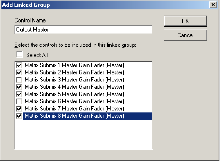
Any Jupiter app that has a matrix has the ability to link together outputs of that matrix for volume control. This is done in the External controller Wizard. When assigning a volume parameter to an ARc, choose the first option in the list, Create New: Matrix Submix Master Gain Fader. Then click on the paper- and-pencil icon on the right to select which channels are to be linked. Any combination is possible. now those submix masters will be linked together with a single volume change.
4. ARC-PS
The ARc-pS is a hub with 8 ARc ports that is handy for providing data and power to many ARcs. To use with Jupiter, simply wire one end of a cAT-5 cable to the 3 pin RS-485 terminal on the back of the ARc-pS. A = pin 4, B= pin 5, Ground = pin 6. Keep the RJ-45 end of the cAT-5 intact for connection to the Jupiter ARc port. no further configuration is required and the network of ARcs will now be available for programming in the Jupiter software.
3. Copy & Paste
After dialing in a module, like an EQ or compressor, you can copy and paste those exact settings to another module of the same type. From the home screen, simply ctrl+click on the module with the settings you want, then drag to the empty module and release. If done properly, you will see the mouse pointer with a plus (+) sign before you release the button over the blank module. open the module and you will see the new settings in place.
2. Remote Terminal – Fake Telnet Utility
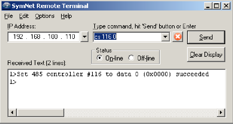
The Jupiter folder on your computer (typically at c:program FilesSymetrix Jupiterbin) has within it an application called Symnet Remote Terminal. originally only available with Symnet software, Remote Terminal is now also bundled with Jupiter, too. Simply launch Remote Terminal, enter the Ip address of the Jupiter device, then give it a control command. The command is anything you would send from a 3rd party controller. (Tip: Enter “Info” to get a readout of the unit’s vital signs, or “Fu” to flash the unit’s front panel lEDs.)
1. Custom Presets
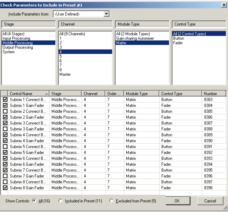
Jupiter can store and recall up to 50 presets. A preset can capture the state of the entire system globally, or can be made custom to only include certain parameters, leaving all others unaffected. To store a custom preset, simply put the software interface in the state needed for the preset. Then, open the Tools menu and click Store preset. choose custom preset, then click choose parameters. This opens a browser window that contains every parameter in the entire system and 4 categories that organize them. narrow your search by category, then check the parameter(s) in the lower window to be included in the preset. (Tip: for 3rd party external control, the pre-assigned controller number for any given parameter is listed in the column on the right.) Repeat up to 50 times to achieve exactly the control you need for your presets
The Symetrix ARC-WEB is a web app remote control for the Jupiter family of audio processors. Now you can use your iPad, iPhone or Android device to control volume, mutes, or presets in your Jupiter 4, 8, or 12. This tech tip will walk you through the steps of setting up and using the Symetrix ARC-WEB.
1) Make sure you have the latest version of the Jupiter software available at www.symetrix.co installed on your Windows compatible computer. (ARC-WEB is included in software versions 2.0 and later.)
2) After selecting and configuring the appropriate Jupiter app for your install, launch the External Controller Wizard found in the Tools menu.
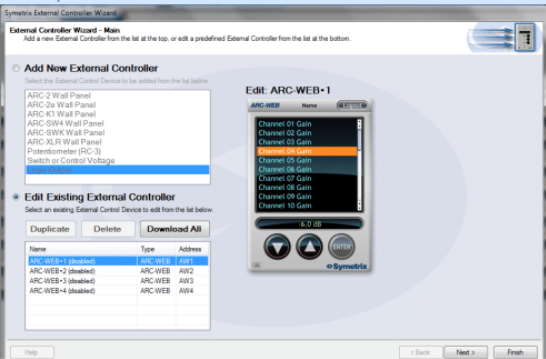
3) Choose Edit Existing External Controller and select one of the four available ARC-WEBs to program.
4) Proceed through the Wizard and follow the instructions to enable, name, and add menus for controls such as volume, mutes and presets. Note, if you are familiar with ARC-2 programming, it is almost identical to programming the ARC-WEB.
5) After you are finished adding up to 24 menus of controls, proceed through the Wizard to configure security if desired. Each ARC-WEB may have a unique username and password.
6) Finally, if the Jupiter software is currently online with the device, the final page of the Wizard will show a button to immediately launch the ARC-WEB in your computer’s Internet browser. (Note, you can repeat steps 2-5 up to four times as four ARC-WEBs are supported per DSP.). To launch ARC-WEB on your iPad, iPhone or Android device simply enter Jupiter’s IP address into the mobile device’s web browser. You can obtain Jupiter’s IP address from the Connection Wizard under the Tools menu, or from the Toolbar if currently online. Make sure Jupiter and your mobile device are both connected to a common Wi-Fi enabled network. Generally, the mobile device will connect to a wireless access point over Wi-Fi and Jupiter will connect to via Ethernet to that wireless access point, or a common switch or router. Internet (WAN) communication is also possible if public access to the Jupiter is enabled by your router or firewall. For information on this, search ‘port forwarding’ in our knowledge base at www. symetrix.co or contact your IT department.
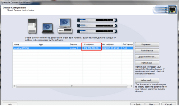
7) Next, we will add an icon to your device’s home screen. This example uses an iPhone. Tap the action button in the bottom middle of the phone’s screen.
8) Then tap ‘Add To Home Screen’.
9) Now give your ARC-WEB a custom name if you wish, then tap the Add button.
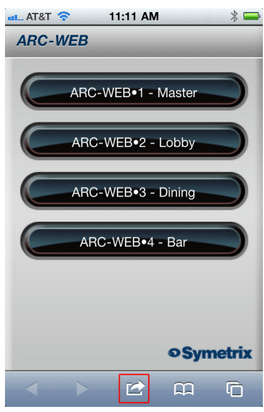
10) Locate and tap the ARC-WEB icon on your home screen and the ARC-WEB app will launch.
11) Then, select one of the four ARC-WEBs..
12) Now, start controlling! Simply select a menu from the drop-down and then use the UP and DOWN buttons to change volume, fire a preset, or turn a mute ‘on’ or ‘off’.